turn SUZUKI JIMNY 2005 3.G Service Workshop Manual
[x] Cancel search | Manufacturer: SUZUKI, Model Year: 2005, Model line: JIMNY, Model: SUZUKI JIMNY 2005 3.GPages: 687, PDF Size: 13.38 MB
Page 442 of 687

Downloaded from www.Manualslib.com manuals search engine ENGINE GENERAL INFORMATION AND DIAGNOSIS 6-85
DTC P0400 Exhaust Gas Recirculation Flow Malfunction
CIRCUIT DESCRIPTION
DTC CONFIRMATION PROCEDURE
1) Turn ignition switch OFF.
Clear DTC with ignition switch ON, check vehicle and environmental condition for :
–Altitude (barometric pressure) : 2400 m, 8000 ft or less (560 mmHg, 75 kPa or more)
–Ambient temp. : –10 °C, 14 °F or higher
–Intake air temp. : 70 °C, 122 °F or lower
1. EGR valve
DTC DETECTING CONDITION POSSIBLE CAUSE
While running at specified vehicle speed after engine warm-up
During deceleration (engine speed high with closed throttle position
ON) in which fuel cut is involved, difference in intake manifold absolute
pressure between when EGR valve is opened at specified value and
when it is closed is larger or smaller than specified value.
✱
✱✱ ✱2 driving cycle detection logic, monitoring once / 1 drivingEGR valve or its circuit
EGR passage
ECM
WARNING:
When performing a road test, select a place where there is no traffic or possibility of a traffic acci-
dent and be very careful during testing to avoid occurrence of an accident.
Road test should be carried out with 2 persons, a driver and a tester, on a level road.
Page 443 of 687

Downloaded from www.Manualslib.com manuals search engine 6-86 ENGINE GENERAL INFORMATION AND DIAGNOSIS
2) Start engine and warm it up to normal operating temperature (70 – 110 °C, 158 – 230 °F) and run it at idle
for 5 min.
3) Increase vehicle speed to 50 – 55 mph, 80 – 88 km/h in 5th gear or in “D” range.
4) Hold throttle valve at that opening position for 2 min. or longer.
5) Increase engine speed to 4000 r/min. in 3rd gear or in “2” range.
6) Release accelerator pedal and with engine brake applied, keep vehicle coasting (fuel cut condition) till
engine speed reaches 1500 r/min.
7) Stop vehicle (don’t turn ignition switch OFF) and confirm test results according to following “Test Result Con-
firmation Flow Table.”
Test Result Confirmation Flow Table
INSPECTION
Step Action Yes No
1 Check DTC in “DTC” mode and pending DTC in
“ON BOARD TEST”.
Is DTC or pending DTC displayed?Proceed to applicable
DTC flow table.Go to Step 2.
2 Set scan tool to “READINESS TESTS” mode
and check if testing has been completed.
Is test completed?No DTC is detected.
(Confirmation test is com-
pleted)Repeat DTC confirmation
procedure.
Step Action Yes No
1Was “Engine Diag. Flow Table” performed? Go to Step 2. Go to “Engine Diag. Flow
Table”.
2 1) Turn ignition switch ON.
2) Does EGR stepper motor operation for 0.6
second after ignition switch OFF?Go to Step 3. Go to Step 6.
3 With ignition switch at OFF, check voltage
between E19-28, 17, 29, 18 terminals of ECM
and body ground. See Fig. 2.
Is voltage about 0 V?Go to Step 4. Go to Step 8.
Page 446 of 687

Downloaded from www.Manualslib.com manuals search engine ENGINE GENERAL INFORMATION AND DIAGNOSIS 6-89
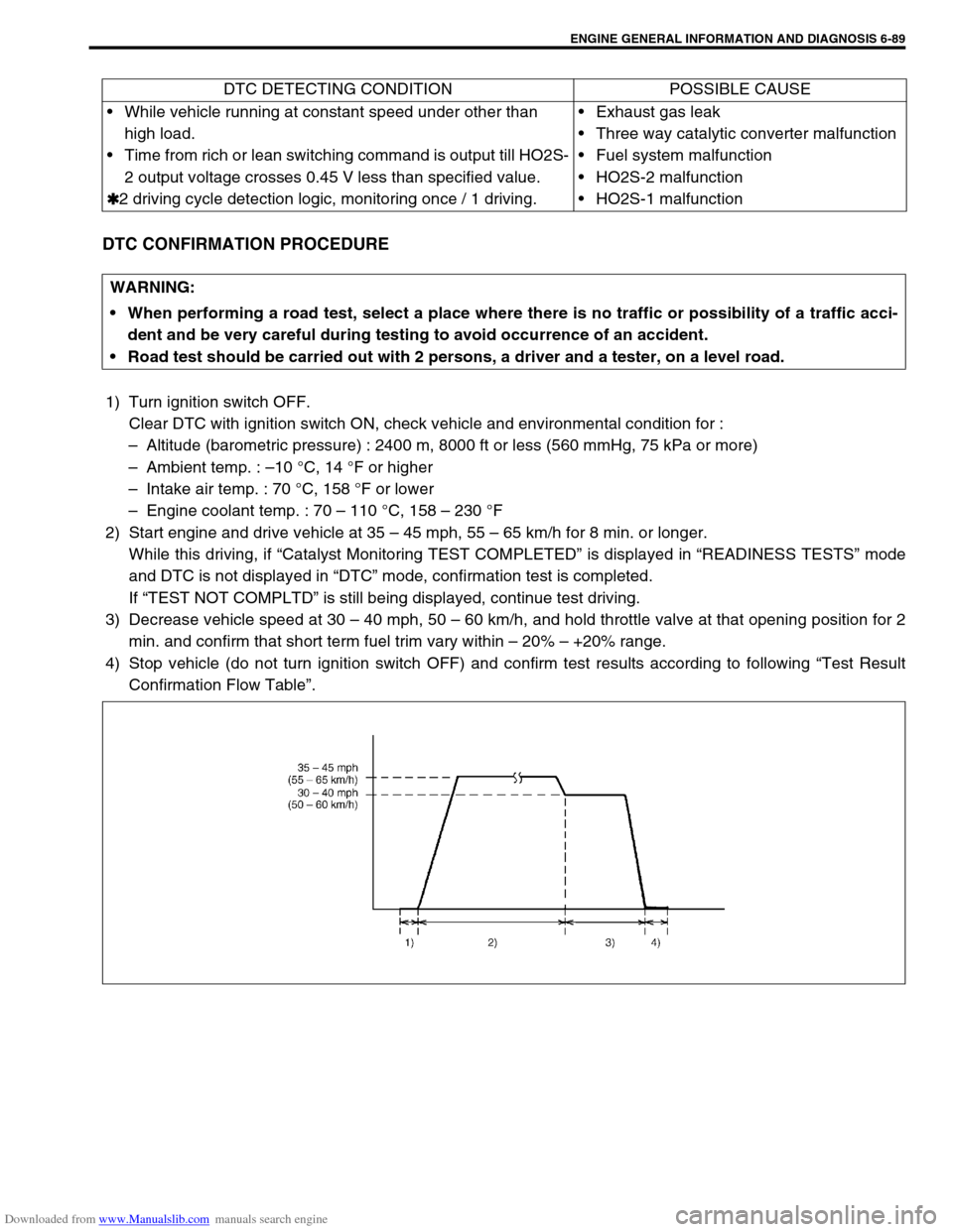
DTC CONFIRMATION PROCEDURE
1) Turn ignition switch OFF.
Clear DTC with ignition switch ON, check vehicle and environmental condition for :
–Altitude (barometric pressure) : 2400 m, 8000 ft or less (560 mmHg, 75 kPa or more)
–Ambient temp. : –10 °C, 14 °F or higher
–Intake air temp. : 70 °C, 158 °F or lower
–Engine coolant temp. : 70 – 110 °C, 158 – 230 °F
2) Start engine and drive vehicle at 35 – 45 mph, 55 – 65 km/h for 8 min. or longer.
While this driving, if “Catalyst Monitoring TEST COMPLETED” is displayed in “READINESS TESTS” mode
and DTC is not displayed in “DTC” mode, confirmation test is completed.
If “TEST NOT COMPLTD” is still being displayed, continue test driving.
3) Decrease vehicle speed at 30 – 40 mph, 50 – 60 km/h, and hold throttle valve at that opening position for 2
min. and confirm that short term fuel trim vary within – 20% – +20% range.
4) Stop vehicle (do not turn ignition switch OFF) and confirm test results according to following “Test Result
Confirmation Flow Table”. DTC DETECTING CONDITION POSSIBLE CAUSE
While vehicle running at constant speed under other than
high load.
Time from rich or lean switching command is output till HO2S-
2 output voltage crosses 0.45 V less than specified value.
✱
✱✱ ✱2 driving cycle detection logic, monitoring once / 1 driving.Exhaust gas leak
Three way catalytic converter malfunction
Fuel system malfunction
HO2S-2 malfunction
HO2S-1 malfunction
WARNING:
When performing a road test, select a place where there is no traffic or possibility of a traffic acci-
dent and be very careful during testing to avoid occurrence of an accident.
Road test should be carried out with 2 persons, a driver and a tester, on a level road.
Page 449 of 687

Downloaded from www.Manualslib.com manuals search engine 6-92 ENGINE GENERAL INFORMATION AND DIAGNOSIS
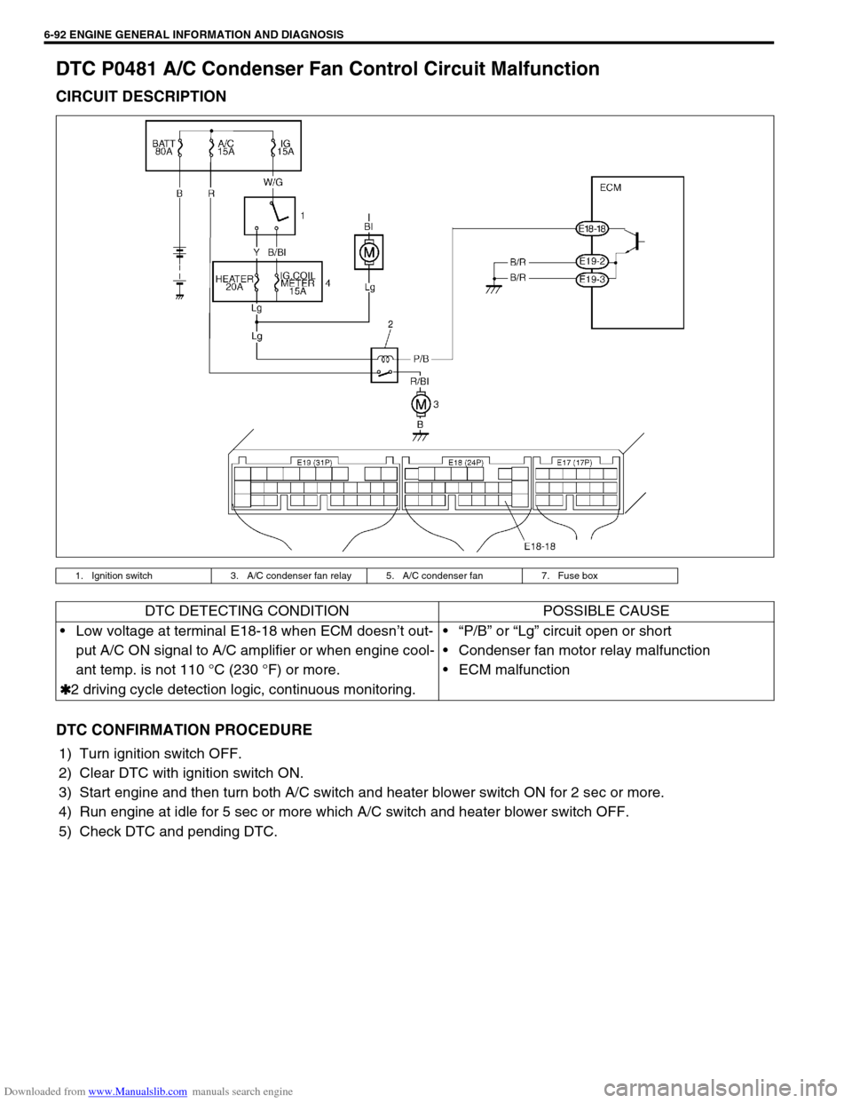
DTC P0481 A/C Condenser Fan Control Circuit Malfunction
CIRCUIT DESCRIPTION
DTC CONFIRMATION PROCEDURE
1) Turn ignition switch OFF.
2) Clear DTC with ignition switch ON.
3) Start engine and then turn both A/C switch and heater blower switch ON for 2 sec or more.
4) Run engine at idle for 5 sec or more which A/C switch and heater blower switch OFF.
5) Check DTC and pending DTC.
1. Ignition switch 3. A/C condenser fan relay 5. A/C condenser fan 7. Fuse box
DTC DETECTING CONDITION POSSIBLE CAUSE
Low voltage at terminal E18-18 when ECM doesn’t out-
put A/C ON signal to A/C amplifier or when engine cool-
ant temp. is not 110 °C (230 °F) or more.
✱
✱✱ ✱2 driving cycle detection logic, continuous monitoring.“P/B” or “Lg” circuit open or short
Condenser fan motor relay malfunction
ECM malfunction
Page 450 of 687
![SUZUKI JIMNY 2005 3.G Service Workshop Manual Downloaded from www.Manualslib.com manuals search engine ENGINE GENERAL INFORMATION AND DIAGNOSIS 6-93
INSPECTION
[A] Fig. 1 for Step 3 / [B] Fig. 2 for Step 3Step Action Yes No
1Was “Engine Diag. F SUZUKI JIMNY 2005 3.G Service Workshop Manual Downloaded from www.Manualslib.com manuals search engine ENGINE GENERAL INFORMATION AND DIAGNOSIS 6-93
INSPECTION
[A] Fig. 1 for Step 3 / [B] Fig. 2 for Step 3Step Action Yes No
1Was “Engine Diag. F](/img/20/7588/w960_7588-449.png)
Downloaded from www.Manualslib.com manuals search engine ENGINE GENERAL INFORMATION AND DIAGNOSIS 6-93
INSPECTION
[A] Fig. 1 for Step 3 / [B] Fig. 2 for Step 3Step Action Yes No
1Was “Engine Diag. Flow Table” performed? Go to Step 2. Go to “Engine Diag.
Flow Table”.
2 Check A/C Condenser Fan Control Relay and its
Circuit.
1) Turn ignition switch ON.
2) Check for voltage at terminal E18-18 of ECM
connector connected, under following condition.
When A/C switch turns OFF : 10 – 14 V
Is voltage as specified?Intermittent trouble or
faulty ECM.
Check for intermittent
referring to “Intermittent
and Poor Connection” in
Section 0A.Go to Step 3.
3 Check A/C Condenser Fan Control Relay.
1) Turn ignition switch OFF and remove A/C con-
denser fan control relay (1). See Fig.1.
2) Check for proper connection to the relay at “P/B”
and “Lg” wire terminals.
3) If OK, then measure resistance between termi-
nals C and D. See Fig.2.
Is it 70 - 110Ω?“Lg” or “P/B” circuit open
or short.
If wires and connections
are OK, substitute a
known-good ECM and
recheck.Replace A/C con-
denser fan control
relay.
Page 452 of 687
![SUZUKI JIMNY 2005 3.G Service Workshop Manual Downloaded from www.Manualslib.com manuals search engine ENGINE GENERAL INFORMATION AND DIAGNOSIS 6-95
INSPECTION
[A] Fig. 1 for Step 5 / [B] Fig. 2 for Step 4 and Step 6Step Action Yes No
1Was “Eng SUZUKI JIMNY 2005 3.G Service Workshop Manual Downloaded from www.Manualslib.com manuals search engine ENGINE GENERAL INFORMATION AND DIAGNOSIS 6-95
INSPECTION
[A] Fig. 1 for Step 5 / [B] Fig. 2 for Step 4 and Step 6Step Action Yes No
1Was “Eng](/img/20/7588/w960_7588-451.png)
Downloaded from www.Manualslib.com manuals search engine ENGINE GENERAL INFORMATION AND DIAGNOSIS 6-95
INSPECTION
[A] Fig. 1 for Step 5 / [B] Fig. 2 for Step 4 and Step 6Step Action Yes No
1Was “Engine Diag. Flow Table” performed? Go to Step 2. Go to “Engine Diag. Flow
Table”.
2 Does speedometer indicate vehicle speed? Go to Step 3. Go to Step 5.
3 Check Vehicle Speed Signal.
Is vehicle speed displayed on scan tool in step
2) and 3) of DTC confirmation procedure?Intermittent trouble or
faulty ECM.
Check for intermittent
referring to “Intermittent
and Poor Connection” in
Section 0A.Go to Step 4.
4 1) Turn ignition switch to OFF position.
2) Disconnect combination meter connec-
tors.Refer to Section 8.
3) Turn ignition switch to ON position, without
running engine.
4) Measure voltage from terminal “c” of VSS
connector to ground. See Fig.2.
Is voltage within 4 – 5 V?Faulty speedometer.“Y” or “Y/G” wire open or
short.
Poor connection of ECM
connector terminal.
If OK, substitute a known-
good ECM and recheck.
5 1) With ignition switch at OFF position, discon-
nect VSS connector.
2) Turn ignition switch to ON position, without
running engine.
3) Measure voltage from terminal “a” to “b” of
VSS connector. See Fig.1.
Is voltage within 10 – 14 V?Go to Step 6.“Bl/B” or “B/Or” wire open
or short.
6 1) Measure voltage from terminal “c” of VSS
connector to ground. See Fig.2.
Is voltage more than 4 V?Go to Step 7.“Y” or “Y/G” wire open or
short.
Poor connection of ECM
connector terminal.
If OK, substitute a known-
good ECM and recheck.
7 1) Remove VSS.
2) Visually inspect VSS sensor signal rotor for
damage.
Was any damage found?Faulty VSS signal rotor. Poor connection of VSS
connector terminal.
If OK, substitute a known-
good VSS and recheck.
Page 453 of 687

Downloaded from www.Manualslib.com manuals search engine 6-96 ENGINE GENERAL INFORMATION AND DIAGNOSIS
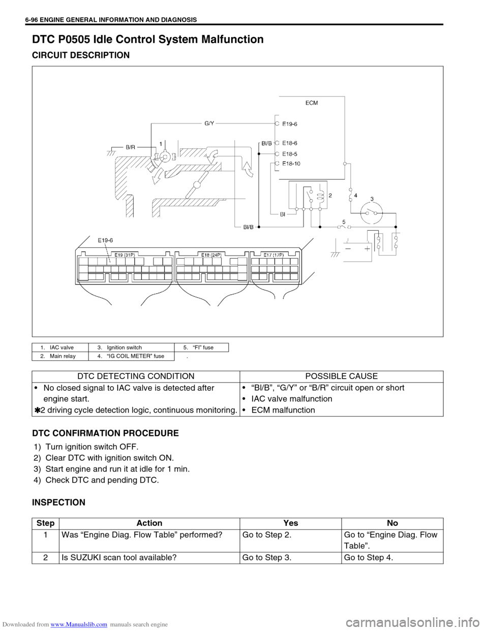
DTC P0505 Idle Control System Malfunction
CIRCUIT DESCRIPTION
DTC CONFIRMATION PROCEDURE
1) Turn ignition switch OFF.
2) Clear DTC with ignition switch ON.
3) Start engine and run it at idle for 1 min.
4) Check DTC and pending DTC.
INSPECTION
1. IAC valve 3. Ignition switch 5.“FI” fuse
2. Main relay 4.“IG COIL METER” fuse .
DTC DETECTING CONDITION POSSIBLE CAUSE
No closed signal to IAC valve is detected after
engine start.
✱
✱✱ ✱2 driving cycle detection logic, continuous monitoring.“Bl/B”, “G/Y” or “B/R” circuit open or short
IAC valve malfunction
ECM malfunction
Step Action Yes No
1Was “Engine Diag. Flow Table” performed? Go to Step 2. Go to “Engine Diag. Flow
Table”.
2 Is SUZUKI scan tool available? Go to Step 3. Go to Step 4.
Page 454 of 687
![SUZUKI JIMNY 2005 3.G Service Workshop Manual Downloaded from www.Manualslib.com manuals search engine ENGINE GENERAL INFORMATION AND DIAGNOSIS 6-97
[A] Fig. 1 for Step 3 / [B] Fig. 2 for Step 43 Check Idle Air Control System.
1) Connect SUZUKI s SUZUKI JIMNY 2005 3.G Service Workshop Manual Downloaded from www.Manualslib.com manuals search engine ENGINE GENERAL INFORMATION AND DIAGNOSIS 6-97
[A] Fig. 1 for Step 3 / [B] Fig. 2 for Step 43 Check Idle Air Control System.
1) Connect SUZUKI s](/img/20/7588/w960_7588-453.png)
Downloaded from www.Manualslib.com manuals search engine ENGINE GENERAL INFORMATION AND DIAGNOSIS 6-97
[A] Fig. 1 for Step 3 / [B] Fig. 2 for Step 43 Check Idle Air Control System.
1) Connect SUZUKI scan tool to DLC with igni-
tion switch OFF, set parking brake and block
drive wheels. See Fig. 1.
2) Warm up engine to normal operating tem-
perature.
3) Clear DTC and select “MISC TEST” mode
on SUZUKI scan tool.
Is it possible to control (increase and reduce)
engine idle speed by using SUZUKI scan tool? Intermittent trouble or
faulty ECM.
Check for intermittent
referring to “Intermittent
and Poor Connection” in
Section 0A.Go to Step 5.
4 Check Idle Air Control System.
1) Remove IAC valve from throttle boy refer-
ring to “IAC Valve” in Section 6E.
2) Check IAC valve for operation referring to
“IAC Valve” in Section 6E. See Fig. 2.
Is check result satisfactory?Intermittent trouble or
faulty ECM.
Check for intermittent
referring to “Intermittent
and Poor Connection” in
Section 0A.Go to Step 5.
5 Check Wire Harness for Open and Short.
1) Turn ignition switch OFF.
2) Disconnect IAC valve connector.
3) Check for proper connection to IAC valve at
each terminals.
4) If OK, disconnect ECM connector.
5) Check for proper connection to ECM at
E19-6 terminal.
6) If OK, check “Bl/B”, “G/Y” and “B/R” circuit
for open and short.
Are they in good condition?Replace IAC valve and
recheck.Repair or replace. Step Action Yes No
Page 455 of 687

Downloaded from www.Manualslib.com manuals search engine 6-98 ENGINE GENERAL INFORMATION AND DIAGNOSIS
DTC P0601 Internal Control Module Memory Check Sum Error (DTC No.71)
DTC CONFIRMATION PROCEDURE
1) Turn ignition switch OFF.
2) Clear DTC with ignition switch ON and then turn ignition switch OFF.
3) Start engine and run it at idle if possible.
4) Check pending DTC in “ON BOARD TEST” or “PENDING DTC” mode and DTC in “DTC” mode.
INSPECTION
Substitute a known-good ECM and recheck.DTC DETECTING CONDITION POSSIBLE CAUSE
DTC P0601 :
Data write error (or check sum error)
when written into ECM
✱
✱✱ ✱2 driving cycle detection logic, continuous monitoring.ECM
Page 456 of 687

Downloaded from www.Manualslib.com manuals search engine ENGINE GENERAL INFORMATION AND DIAGNOSIS 6-99
DTC P1450 Barometric Pressure Sensor Low / High Input
DTC P1451 Barometric Pressure Sensor Performance Problem
WIRING DIAGRAM / CIRCUIT DESCRIPTION
Barometric pressure sensor is installed in ECM.
DTC CONFIRMATION PROCEDURE
1) Turn ignition switch OFF.
2) Clear DTC with ignition switch ON.
3) Turn ignition switch ON for 2 sec., crank engine for 2 sec. and run it at idle for 1 min.
4) Check pending DTC in “ON BOARD TEST” or “PENDING DTC” mode and DTC in “DTC” mode.
INSPECTION
DTC P1450 :
Substitute a known-good ECM and recheck.
DTC P1451 :
DTC DETECTING CONDITION POSSIBLE CAUSE
DTC P1450 :
Barometric pressure sensor voltage is 4.7 V or higher, or
1.6 V or lowerECM (barometric pressure sensor) malfunc-
tion
DTC P1451 :
Vehicle stopped
Engine cranking
Difference between barometric pressure and intake mani-
fold absolute pressure is 26 kPa, 200 mmHg or more.
Difference between intake manifold absolute pressure at
engine start and pressure after engine start is less than 1.3
kPa, 10 mmHg.
✱
✱✱ ✱2 driving cycle detection logic, monitoring once / 1 driving.ECM (barometric pressure sensor) malfunc-
tion
NOTE:
Note that atmospheric pressure varies depending on weather conditions as well as altitude.
Take that into consideration when performing these check.
Step Action Yes No
1Was “Engine Diag. Flow Table” performed? Go to Step 2. Go to “Engine Diag. Flow
Table”.
2 1) Connect scan tool to DLC with ignition
switch OFF. See Fig.1.
2) Turn ignition switch ON and select “DATA
LIST” mode on scan tool.
3) Check manifold absolute pressure.
Is it barometric pressure (approx. 100 kPa, 760
mmHg) at sea level?Substitute a known-good
ECM and recheck.Go to Step 3.