200 SUZUKI JIMNY 2005 3.G Service User Guide
[x] Cancel search | Manufacturer: SUZUKI, Model Year: 2005, Model line: JIMNY, Model: SUZUKI JIMNY 2005 3.GPages: 687, PDF Size: 13.38 MB
Page 423 of 687

Downloaded from www.Manualslib.com manuals search engine 6-66 ENGINE GENERAL INFORMATION AND DIAGNOSIS
DTC P0141 Heated Oxygen Sensor (HO2S) Heater Circuit Malfunction (Sen-
sor-2)
CIRCUIT DESCRIPTION
DTC CONFIRMATION PROCEDURE
1) Turn ignition switch OFF once and then ON.
2) Clear DTC, start engine and warm up engine to normal operating temperature.
3) Keep it at 2000 r/min for 2 min.
4) Check pending DTC in “ON BOARD TEST” or “PENDING DTC” mode and DTC in “DTC” mode.
DTC DETECTING CONDITION POSSIBLE CAUSE
DTC will set when A or B condition it met.
1) Low voltage at terminal E18-4 for specified time after
engine start or while engine running at high load.
2) High voltage at terminal E18-4 while engine running
under other than above condition.
✱
✱✱ ✱2 driving cycle detection logic, continuous monitoring.HO2S-2 heater circuit open or shorted to ground
ECM malfunction
Page 426 of 687

Downloaded from www.Manualslib.com manuals search engine ENGINE GENERAL INFORMATION AND DIAGNOSIS 6-69
DTC CONFIRMATION PROCEDURE
1) Turn ignition switch OFF.
2) Clear DTC with ignition switch ON.
3) Check vehicle and environmental condition for :
–Altitude (barometric pressure) : 2400 m, 8000 ft or less (560 mmHg, 75 kPa or more)
–Ambient temp. : –10 °C, 14 °F or higher
–Intake air temp. : 70 °C, 158 °F or lower
4) Start engine and drive vehicle under usual driving condition (described in DTC confirmation procedure of
DTC P0136) for 5 min. or longer and until engine is warmed up to normal operating temperature.
5) Keep vehicle speed at 30 – 40 mph, 50 – 60 km/h in 5th gear or “D” range for 5 min. or more.
6) Stop vehicle (do not turn ignition switch OFF).
7) Check pending DTC in “ON BOARD TEST” or “PENDING DTC” mode and DTC in “DTC” mode.
INSPECTION
WARNING:
When performing a road test, select a place where there is no traffic or possibility of a traffic acci-
dent and be very careful during testing to avoid occurrence of an accident.
Road test should be carried out with 2 persons, a driver and a tester on a level road.
Step Action Yes No
1Was “Engine Diag. Flow Table” performed? Go to Step 2. Go to “Engine Diag.
Flow Table”.
2 Is there DTC(s) other than fuel system
(DTC P0171 / P0172)?Go to applicable DTC
Diag. Flow Table.Go to Step 3.
3 Check HO2S-1 Output Voltage.
1) Connect scan tool to DLC with ignition switch
OFF. See Fig. 1.
2) Warm up engine to normal operating tempera-
ture and keep it at 2000 r/min. for 60 sec.
3) Repeat racing engine (Repeat depressing
accelerator pedal 5 to 6 times continuously and
take foot off from pedal to enrich and enlean
A/F mixture).
Does HO2S-1 output voltage deflect between
below 0.3 V and over 0.6 V repeatedly?Go to Step 4. Go to DTC P0130 Diag.
Flow Table (HO2S-1 cir-
cuit check).
4 Check Fuel Pressure (Refer to Section 6E for
details).
1) Release fuel pressure from fuel feed line.
2) Install fuel pressure gauge. See Fig. 2.
3) Check fuel pressure.
Fuel pressure specification
With fuel pump operating and engine at stop :
270 – 310 kPa, 2.7 – 3.1 kg/cm
2, 38.4 – 44.0 psi.
At specified idle speed :
210 – 260 kPa, 2.1 – 2.6 kg/cm
2, 29.8 – 37.0 psi.
Is measured value as specified?Go to Step 5. Go to Diag. Flow Table
B-3 Fuel Pressure
Check.
Page 429 of 687

Downloaded from www.Manualslib.com manuals search engine 6-72 ENGINE GENERAL INFORMATION AND DIAGNOSIS
DTC P0300 Random Misfire Detected (Misfire Detected at 2 or More Cylinders)
DTC P0301 Cylinder 1 Misfire Detected
DTC P0302 Cylinder 2 Misfire Detected
DTC P0303 Cylinder 3 Misfire Detected
DTC P0304 Cylinder 4 Misfire Detected
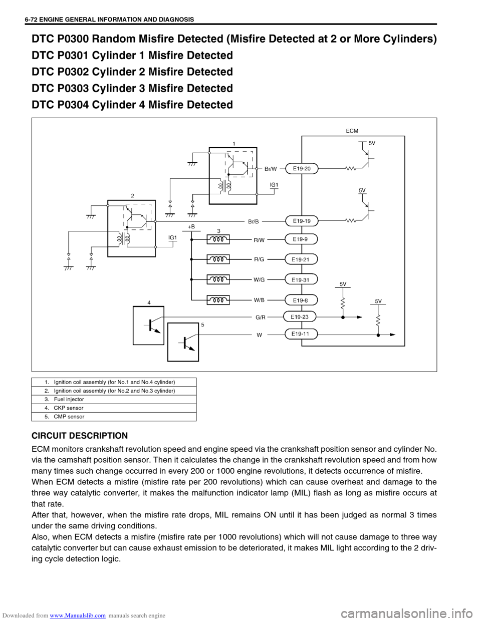
CIRCUIT DESCRIPTION
ECM monitors crankshaft revolution speed and engine speed via the crankshaft position sensor and cylinder No.
via the camshaft position sensor. Then it calculates the change in the crankshaft revolution speed and from how
many times such change occurred in every 200 or 1000 engine revolutions, it detects occurrence of misfire.
When ECM detects a misfire (misfire rate per 200 revolutions) which can cause overheat and damage to the
three way catalytic converter, it makes the malfunction indicator lamp (MIL) flash as long as misfire occurs at
that rate.
After that, however, when the misfire rate drops, MIL remains ON until it has been judged as normal 3 times
under the same driving conditions.
Also, when ECM detects a misfire (misfire rate per 1000 revolutions) which will not cause damage to three way
catalytic converter but can cause exhaust emission to be deteriorated, it makes MIL light according to the 2 driv-
ing cycle detection logic.
1. Ignition coil assembly (for No.1 and No.4 cylinder)
2. Ignition coil assembly (for No.2 and No.3 cylinder)
3. Fuel injector
4. CKP sensor
5. CMP sensor
Page 430 of 687

Downloaded from www.Manualslib.com manuals search engine ENGINE GENERAL INFORMATION AND DIAGNOSIS 6-73
DTC CONFIRMATION PROCEDURE
1) Turn ignition switch OFF.
2) Clear DTC with ignition switch ON.
3) Check vehicle and environmental condition for :
–Altitude (barometric pressure) : 2400 m, 8000 ft or less (560 mmHg, 75 kPa or more)
–Ambient temp. : –10 °C, 14 °F or higher
–Intake air temp. : 70 °C, 158 °F or lower
–Engine coolant temp. : – 10 – 110 °C, 14 – 230 °F
4) Start engine and keep it at idle for 2 min. or more.
5) Check DTC in “DTC” mode and pending DTC in “ON BOARD TEST” or “PENDING DTC” mode.
6) If DTC is not detected at idle, consult usual driving based on information obtained in “Customer complaint
analysis” and “Freeze frame data check”.
INSPECTION
DTC DETECTING CONDITION POSSIBLE CAUSE
Engine under other than high revolution condition
Not on rough road
Engine speed changing rate (below specified value)
Manifold absolute pressure changing rate (below
specified value)
Throttle opening changing rate (below specified
value)
Misfire rate per 200 or 1000 engine revolutions (how
much and how often crankshaft revolution speed
changes) is higher than specified valueEngine overheating
Vacuum leaks (air inhaling) from air intake system
Ignition system malfunction (spark plug(s), high-
tension cord(s), ignition coil assembly)
Fuel pressure out of specification
Fuel injector malfunction (clogged or leakage)
Engine compression out of specification
Valve lash (clearance) out of specification
Manifold absolute pressure sensor malfunction
Engine coolant temp. sensor malfunction
PCV valve malfunction
EVAP control system malfunction
EGR system malfunction
NOTE:
Among different types of random misfire, if misfire occurs at cylinders 1 and 4 or cylinders 3 and 2
simultaneously, it may not possible to reconfirm DTC by using the following DTC confirmation proce-
dure. When diagnosing the trouble of DTC P0300 (Random misfire detected) of the engine which is
apparently misfiring, even if DTC P0300 cannot be reconfirmed by using the following DTC confirma-
tion procedure, proceed to the following Diag. Flow Table.
WARNING:
When performing a road test, select a place where there is no traffic or possibility of a traffic acci-
dent and be very careful during testing to avoid occurrence of an accident.
Road test should be carried out with 2 persons, a driver and a tester.
Step Action Yes No
1Was “Engine Diag. Flow Table” performed? Go to Step 2. Go to “Engine
Diag. Flow Table”.
2 Is there DTC other than Fuel system (DTC P0171/
P0172) and misfire (DTC P0300 – P0304)?Go to applicable DTC
Diag. Flow Table.Go to Step 3.
Page 436 of 687

Downloaded from www.Manualslib.com manuals search engine ENGINE GENERAL INFORMATION AND DIAGNOSIS 6-79
DTC P0335 (DTC No.23) Crankshaft Position (CKP) Sensor Circuit Malfunction
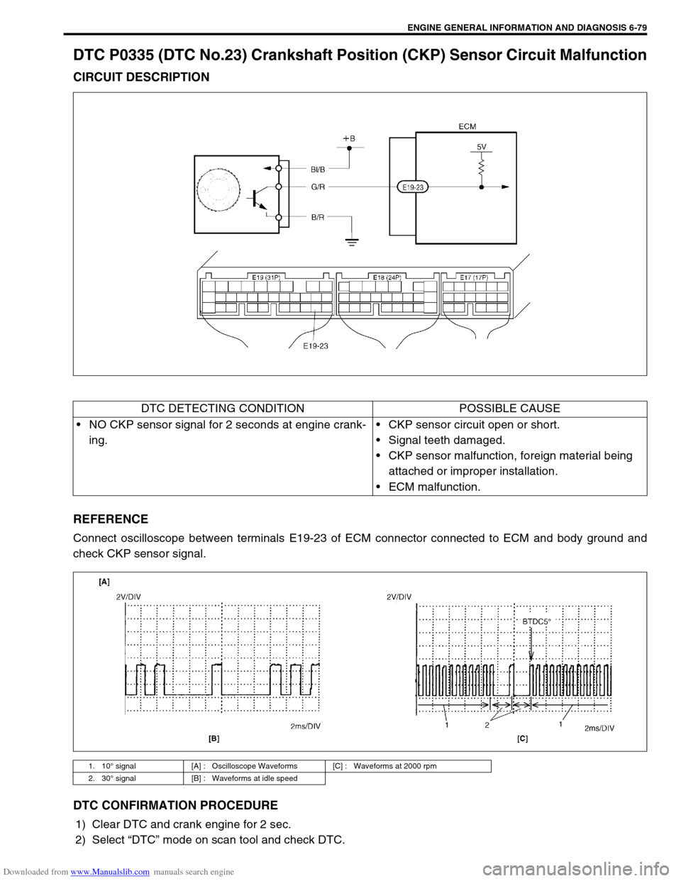
CIRCUIT DESCRIPTION
REFERENCE
Connect oscilloscope between terminals E19-23 of ECM connector connected to ECM and body ground and
check CKP sensor signal.
DTC CONFIRMATION PROCEDURE
1) Clear DTC and crank engine for 2 sec.
2) Select “DTC” mode on scan tool and check DTC.
DTC DETECTING CONDITION POSSIBLE CAUSE
NO CKP sensor signal for 2 seconds at engine crank-
ing.CKP sensor circuit open or short.
Signal teeth damaged.
CKP sensor malfunction, foreign material being
attached or improper installation.
ECM malfunction.
1. 10° signal [A] : Oscilloscope Waveforms [C] : Waveforms at 2000 rpm
2. 30° signal [B] : Waveforms at idle speed
Page 456 of 687

Downloaded from www.Manualslib.com manuals search engine ENGINE GENERAL INFORMATION AND DIAGNOSIS 6-99
DTC P1450 Barometric Pressure Sensor Low / High Input
DTC P1451 Barometric Pressure Sensor Performance Problem
WIRING DIAGRAM / CIRCUIT DESCRIPTION
Barometric pressure sensor is installed in ECM.
DTC CONFIRMATION PROCEDURE
1) Turn ignition switch OFF.
2) Clear DTC with ignition switch ON.
3) Turn ignition switch ON for 2 sec., crank engine for 2 sec. and run it at idle for 1 min.
4) Check pending DTC in “ON BOARD TEST” or “PENDING DTC” mode and DTC in “DTC” mode.
INSPECTION
DTC P1450 :
Substitute a known-good ECM and recheck.
DTC P1451 :
DTC DETECTING CONDITION POSSIBLE CAUSE
DTC P1450 :
Barometric pressure sensor voltage is 4.7 V or higher, or
1.6 V or lowerECM (barometric pressure sensor) malfunc-
tion
DTC P1451 :
Vehicle stopped
Engine cranking
Difference between barometric pressure and intake mani-
fold absolute pressure is 26 kPa, 200 mmHg or more.
Difference between intake manifold absolute pressure at
engine start and pressure after engine start is less than 1.3
kPa, 10 mmHg.
✱
✱✱ ✱2 driving cycle detection logic, monitoring once / 1 driving.ECM (barometric pressure sensor) malfunc-
tion
NOTE:
Note that atmospheric pressure varies depending on weather conditions as well as altitude.
Take that into consideration when performing these check.
Step Action Yes No
1Was “Engine Diag. Flow Table” performed? Go to Step 2. Go to “Engine Diag. Flow
Table”.
2 1) Connect scan tool to DLC with ignition
switch OFF. See Fig.1.
2) Turn ignition switch ON and select “DATA
LIST” mode on scan tool.
3) Check manifold absolute pressure.
Is it barometric pressure (approx. 100 kPa, 760
mmHg) at sea level?Substitute a known-good
ECM and recheck.Go to Step 3.
Page 457 of 687
![SUZUKI JIMNY 2005 3.G Service User Guide Downloaded from www.Manualslib.com manuals search engine 6-100 ENGINE GENERAL INFORMATION AND DIAGNOSIS
[A] Fig. 1 for Step 2 / [B] Fig. 2 for Step 3
Table 13 Check MAP Sensor
1) Remove MAP sensor fro SUZUKI JIMNY 2005 3.G Service User Guide Downloaded from www.Manualslib.com manuals search engine 6-100 ENGINE GENERAL INFORMATION AND DIAGNOSIS
[A] Fig. 1 for Step 2 / [B] Fig. 2 for Step 3
Table 13 Check MAP Sensor
1) Remove MAP sensor fro](/img/20/7588/w960_7588-456.png)
Downloaded from www.Manualslib.com manuals search engine 6-100 ENGINE GENERAL INFORMATION AND DIAGNOSIS
[A] Fig. 1 for Step 2 / [B] Fig. 2 for Step 3
Table 13 Check MAP Sensor
1) Remove MAP sensor from intake manifold
and connect vacuum pump gauge to MAP
sensor. See Fig. 2.
2) Connect scan tool to DLC and turn ignition
switch ON.
3) Check intake manifold absolute pressure
displayed on scan tool for specified value.
See Table 1.
Is check result satisfactory?Check air intake system
for air being drawn in and
engine compression.
If OK, then substitute a
known-good ECM and
recheck.Replace MAP sensor. Step Action Yes No
Applying Vacuum Displayed Value on Scan Tool
0 Barometric pressure
(Approx. 100 kPa, 760 mmHg)
027 kPa
200 mmHgBarometric pressure – 27 kPa
(Approx. 73 kPa, 560 mmHg)
67 kPa
500 mmHgBarometric pressure – 67 kPa
(Approx. 33 kPa, 260 mmHg)
Page 472 of 687

Downloaded from www.Manualslib.com manuals search engine ENGINE GENERAL INFORMATION AND DIAGNOSIS 6-115
3 Is engine idle speed kept specified speed even
with headlight ON?System is in good condi-
tion.Check IAC system for
operation referring to
Step 3 or Step 4 of DTC
P0505 Diag. Flow Table.
4 Was idle speed higher than specification in Step
1?Go to Step 5. Go to Step 8.
5 Check A/C (input) signal circuit referring to Step 1
of Table B-5 A/C Signal Circuit Check, if
equipped. (A/C signal can be also checked by
using SUZUKI scan tool.)
Is it in good condition?Go to Step 6. Repair or replace A/C
signal circuit or A/C sys-
tem.
6 Check IAC system referring to Step 2 to Step 4 of
DTC P0505 Diag. Flow Table.
Is check result satisfactory?Go to Step 7. Go to Step 5 of DTC
P0505 Diag. Flow Table.
7 Was IAC duty less than about 3% (or more than
about 97% for OFF duty meter) in Step 1 of this
table?Check abnormal air
inhaling from air intake
system, PCV valve and
EVAP canister purge
control system.Check TP sensor
(closed throttle position)
and ECT sensor for per-
formance.
If sensors are OK, sub-
stitute a known-good
ECM.
8 Is SUZUKI scan tool available? Go to Step 9. Go to Step 10.
9 Check PNP signal (“D” range signal).
1) Connect SUZUKI scan tool to DLC with igni-
tion switch OFF.
2) Turn ignition switch ON and check PNP signal
(“P/N” and “D” range) on display when shifting
selector lever to each range. See Table 1.
Is check result satisfactory?Go to Step 11. Repair or replace.
10 Check PNP signal (“D” range signal).
1) Turn ignition switch ON.
2) Check voltage at terminal E17-6 of ECM con-
nector connected. See Fig. 1 and Table 1.
Is check result satisfactory?Go to Step 11. Repair or replace.
11 Check IAC system referring to Step 2 to Step 4 of
DTC P0505 Diag. Flow Table.
Is check result satisfactory?Go to Step 12. Go to Step 5 of DTC
P0505 Diag. Flow Table.
12 Was IAC duty more than about 30% or ✱40% (or
less than 70% or ✱60% for OFF duty meter) in
Step 1 of this table? See NOTE.Check parts or system
which can cause engine
low idle.
Accessory engine load
Clog of air passage
Etc.Substitute a known-good
ECM and recheck. Step Action Yes No
NOTE:
Duty value with (
✱
✱✱ ✱) are applicable to vehicle used at high altitude (higher than 2000 m or 6560 ft).
Page 492 of 687

Downloaded from www.Manualslib.com manuals search engine ENGINE MECHANICAL (M13 ENGINE) 6A1-11
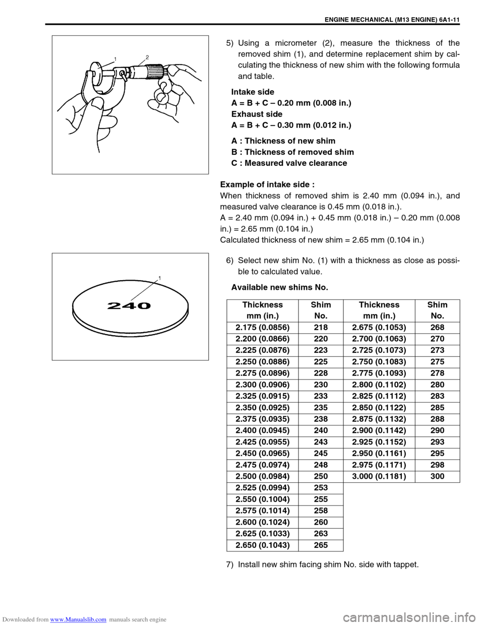
5) Using a micrometer (2), measure the thickness of the
removed shim (1), and determine replacement shim by cal-
culating the thickness of new shim with the following formula
and table.
Intake side
A = B + C – 0.20 mm (0.008 in.)
Exhaust side
A = B + C – 0.30 mm (0.012 in.)
A : Thickness of new shim
B : Thickness of removed shim
C : Measured valve clearance
Example of intake side :
When thickness of removed shim is 2.40 mm (0.094 in.), and
measured valve clearance is 0.45 mm (0.018 in.).
A = 2.40 mm (0.094 in.) + 0.45 mm (0.018 in.) – 0.20 mm (0.008
in.) = 2.65 mm (0.104 in.)
Calculated thickness of new shim = 2.65 mm (0.104 in.)
6) Select new shim No. (1) with a thickness as close as possi-
ble to calculated value.
Available new shims No.
7) Install new shim facing shim No. side with tappet.
Thickness
mm (in.)Shim
No.Thickness
mm (in.)Shim
No.
2.175 (0.0856) 218 2.675 (0.1053) 268
2.200 (0.0866) 220 2.700 (0.1063) 270
2.225 (0.0876) 223 2.725 (0.1073) 273
2.250 (0.0886) 225 2.750 (0.1083) 275
2.275 (0.0896) 228 2.775 (0.1093) 278
2.300 (0.0906) 230 2.800 (0.1102) 280
2.325 (0.0915) 233 2.825 (0.1112) 283
2.350 (0.0925) 235 2.850 (0.1122) 285
2.375 (0.0935) 238 2.875 (0.1132) 288
2.400 (0.0945) 240 2.900 (0.1142) 290
2.425 (0.0955) 243 2.925 (0.1152) 293
2.450 (0.0965) 245 2.950 (0.1161) 295
2.475 (0.0974) 248 2.975 (0.1171) 298
2.500 (0.0984) 250 3.000 (0.1181) 300
2.525 (0.0994) 253
2.550 (0.1004) 255
2.575 (0.1014) 258
2.600 (0.1024) 260
2.625 (0.1033) 263
2.650 (0.1043) 265
Page 627 of 687

Downloaded from www.Manualslib.com manuals search engine 6E-22 ENGINE AND EMISSION CONTROL SYSTEM
Fuel Delivery System
Fuel pressure inspection
1) Relieve fuel pressure in fuel feed line referring to “Fuel Pres-
sure Relief Procedure” in Section 6.
2) Disconnect fuel feed hose from fuel delivery pipe.
3) Connect special tools and hose between fuel delivery pipe
(1) and fuel feed hose (2) as shown in figure, and clamp
hoses securely to ensure no leaks occur during checking.
Special tool
(A) : 09912-58442
(B) : 09912-58432
(C) : 09912-58490
4) Check that battery voltage is above 11 V.
5) Turn ignition switch ON to operate fuel pump and after 2 sec-
onds turn it OFF. Repeat this 3 or 4 times and then check
fuel pressure.
Fuel pressure specification WARNING:
Be sure to perform work in a well-ventilated area and
away from any open flames, or there is a risk of a fire
breaking out.
CAUTION:
A small amount of fuel may be released when fuel hose is
disconnected. Place container under the joint with a
shop cloth so that released fuel is caught in container or
absorbed in cloth. Place that cloth in an approved con-
tainer.
3. Fuel return pipe
CONDITION FUEL PRESSURE
With fuel pump operating and
engine stopped270 – 310 kPa
2.7 – 3.1 kg/cm
2,
38.4 – 44.0 psi
At specified idle speed 210 – 260 kPa
2.1 – 2.6 kg/cm
2,
29.8 – 37.0 psi
With 1 min. after engine (fuel
pump) stop (Pressure
reduces as time passes)over 200 kPa
2.0 kg/cm
2, 28.4 psi