200 SUZUKI JIMNY 2005 3.G Service Workshop Manual
[x] Cancel search | Manufacturer: SUZUKI, Model Year: 2005, Model line: JIMNY, Model: SUZUKI JIMNY 2005 3.GPages: 687, PDF Size: 13.38 MB
Page 1 of 687

Downloaded from www.Manualslib.com manuals search engine IMPORTANT
WARNING/CAUTION/NOTE
Please read this manual and follow its instructions carefully. To emphasize special information, the words
WARNING, CAUTION
and NOTE
have special meanings. Pay special attention to the messages highlighted by
these signal words.
WARNING:
Indicates a potential hazard that could result in death or injury.
CAUTION:
Indicates a potential hazard that could result in vehicle damage.
NOTE:
Indicates special information to make maintenance easier or instructions clearer.
WARNING:
This service manual is intended for authorized Suzuki dealers and qualified service mechanics only.
Inexperienced mechanics or mechanics without the proper tools and equipment may not be able to
properly perform the services described in this manual.
Improper repair may result in injury to the mechanic and may render the vehicle unsafe for the driver
and passengers.
WARNING:
For vehicles equipped with a Supplemental Restraint or Air Bag System:
• Service on and around the air bag system components or wiring must be performed only by an
authorized SUZUKI dealer. Refer to “Air Bag System Components and Wiring Location View” under
“General Description” in air bag system section in order to confirm whether you are performing ser-
vice on or near the air bag system components or wiring. Please observe all WARNINGS and “Ser-
vice Precautions” under “On-Vehicle Service” in air bag system section before performing service
on or around the air bag system components or wiring. Failure to follow WARNINGS could result in
unintentional activation of the system or could render the system inoperative. Either of these two
conditions may result in severe injury.
If the air bag system and another vehicle system both need repair, Suzuki recommends that the air
bag system be repaired first, to help avoid unintended air bag system activation.
Do not modify the steering wheel, instrument panel or any other air bag system component on or
around air bag system components or wiring. Modifications can adversely affect air bag system
performance and lead to injury.
If the vehicle will be exposed to temperatures over 93°C (200°F), for example, during a paint baking
process, remove the air bag system components, that is air bag or inflator modules, SDM and/or
seat belt with pretensioner, beforehand to avoid component damage or unintended activation.
Page 2 of 687

Downloaded from www.Manualslib.com manuals search engine FOREWORD
This manual contains procedures for diagnosis, maintenance, adjustments, minor service operations, replace-
ment of components (Service) and for disassembly and assembly of major components (Unit Repair-Overhaul).
Applicable model: JIMNY (SN413) of and after the vehicle identification numbers below.
The contents are classified into sections each of which is given a section number as indicated in the Table of
Contents on following page. And on the first page of each individual section is an index of that section.
This manual should be kept in a handy place for ready reference of the service work.
Strict observance of the so specified items will enable one to obtain the full performance of the vehicle.
When replacing parts or servicing by disassembling, it is recommended to use SUZUKI genuine parts, tools and
service materials (lubricant, sealants, etc.) as specified in each description.
All information, illustrations and specifications contained in this literature are based on the latest product infor-
mation available at the time of publication approval. And used as the main subject of description is the vehicle of
standard specifications among others.
Therefore, note that illustrations may differ from the vehicle being actually serviced.
The right is reserved to make changes at any time without notice.
Related Manual
© COPYRIGHT SUZUKI MOTOR CORPORATION 2002JSAFJA43V00140001
JSAFJB43V00140001
JSAFJB43V20140001
JSAFJB43V24140001
JSAFJB43V34140001
JS3JB43V 24140001
JS3JB43V 34140001
Manual Name Manual No.
JIMNY (SN413) WIRING DIAGRAM MANUAL 99512-81A20-015
Page 8 of 687

Downloaded from www.Manualslib.com manuals search engine GENERAL INFORMATION 0A-3
Precautions
Precaution for Vehicles Equipped with a Sup-
plemental Restraint (Air Bag) System
Diagnosis
When troubleshooting air bag system, be sure to follow “Air
Bag Diagnostic System Check” in Section 10B. Bypassing
these procedures may result in extended diagnostic time,
incorrect diagnosis, and incorrect parts replacement.
Never use electrical test equipment other than that specified
in this manual. WARNING:
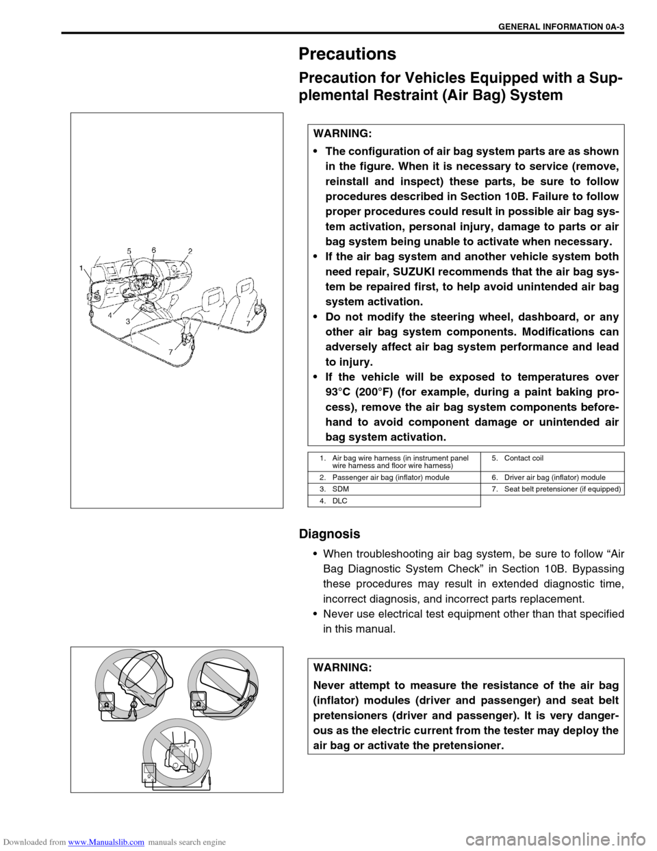
The configuration of air bag system parts are as shown
in the figure. When it is necessary to service (remove,
reinstall and inspect) these parts, be sure to follow
procedures described in Section 10B. Failure to follow
proper procedures could result in possible air bag sys-
tem activation, personal injury, damage to parts or air
bag system being unable to activate when necessary.
If the air bag system and another vehicle system both
need repair, SUZUKI recommends that the air bag sys-
tem be repaired first, to help avoid unintended air bag
system activation.
Do not modify the steering wheel, dashboard, or any
other air bag system components. Modifications can
adversely affect air bag system performance and lead
to injury.
If the vehicle will be exposed to temperatures over
93°C (200°F) (for example, during a paint baking pro-
cess), remove the air bag system components before-
hand to avoid component damage or unintended air
bag system activation.
1. Air bag wire harness (in instrument panel
wire harness and floor wire harness)5. Contact coil
2. Passenger air bag (inflator) module 6. Driver air bag (inflator) module
3. SDM 7. Seat belt pretensioner (if equipped)
4. DLC
WARNING:
Never attempt to measure the resistance of the air bag
(inflator) modules (driver and passenger) and seat belt
pretensioners (driver and passenger). It is very danger-
ous as the electric current from the tester may deploy the
air bag or activate the pretensioner.
Page 44 of 687

Downloaded from www.Manualslib.com manuals search engine MAINTENANCE AND LUBRICATION 0B-13
Parking Brake Lever and Cable
INSPECTION
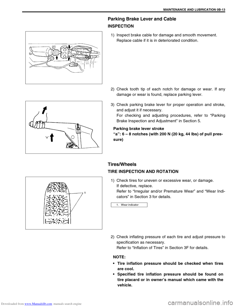
1) Inspect brake cable for damage and smooth movement.
Replace cable if it is in deteriorated condition.
2) Check tooth tip of each notch for damage or wear. If any
damage or wear is found, replace parking lever.
3) Check parking brake lever for proper operation and stroke,
and adjust it if necessary.
For checking and adjusting procedures, refer to “Parking
Brake Inspection and Adjustment” in Section 5.
Parking brake lever stroke
“a”: 6 – 8 notches (with 200 N (20 kg, 44 lbs) of pull pres-
sure)
Tires/Wheels
TIRE INSPECTION AND ROTATION
1) Check tires for uneven or excessive wear, or damage.
If defective, replace.
Refer to “Irregular and/or Premature Wear” and “Wear Indi-
cators” in Section 3 for details.
2) Check inflating pressure of each tire and adjust pressure to
specification as necessary.
Refer to “Inflation of Tires” in Section 3F for details.
1. Wear indicator
NOTE:
Tire inflation pressure should be checked when tires
are cool.
Specified tire inflation pressure should be found on
tire placard or in owner’s manual which came with the
vehicle.
Page 74 of 687

Downloaded from www.Manualslib.com manuals search engine AIR CONDITIONING (OPTIONAL) 1B-13
CROSSING POINT OF CENTER VENTILATION LOUVER TEMPERATURE AND RECIRCULATION AIR
INLET TEMPERATURE
Detail diagnosis table (Ambient temperature at 30°C (86°F))
Condition Possible Cause Correction
Crossing point is
higher than accept-
able range
(“E” area)Insufficient or excessive charge of refrigerant Check refrigerant pressure
Dirty or bent A/C evaporator fins Clean or repair
Air leakage from cooling (heater) unit or air duct Repair or replace
Malfunctioning, switch over function of door in
cooling (heater) unitRepair or replace
Compressor malfunction Check compressor
Crossing point is
lower than acceptable
range
(“F” area)Insufficient air volume from center duct (Heater
blower malfunction)Check blower motor and fan
Compressor malfunction Check compressor
Condition
Possible Cause Correction MANIFOLD
GAUGEMPa
(kg/cm
2)
(psi)Detail
Lo Hi
0.23 – 0.35
(2.3 – 3.5)
(33 – 50)1.4 – 1.75
(14 – 17.5)
(200 – 249)Normal condition
––
Negative
pressure0.5 – 0.6
(5 – 6)
(71.2 – 85.3)The low pressure side
reads a negative pres-
sure, and the high pres-
sure side reads an
extremely low pressure.
Presence of frost
around tubing to and
from receiver / dryer
and expansion valve.Dust particles or water
droplets are either stuck
or frozen inside expan-
sion valve, preventing the
refrigerant from flowing.Clean expansion valve.
Replace it if it cannot be
cleaned.
Replace receiver / dryer.
Evacuate the A/C sys-
tem and recharge with
fresh refrigerant.
Normal :
0.23 – 0.35
(2.3 – 3.5)
(33 – 50)
↑
↑ ↑ ↑ ↓
↓↓ ↓
Abnormal :
Negative
pressureNormal :
1.4 – 1.75
(14 – 17.5)
(200 – 249)
↑
↑ ↑ ↑ ↓
↓↓ ↓
Abnormal :
0.69 – 0.98
(7 – 10)
(100 – 142)During A/C operation,
the low pressure side
sometimes indicates
negative pressure, and
sometimes normal
pressure. Also high
pressure side reading
fluctuates between the
abnormal and normal
pressure.Expansion valve is frozen
due to moisture in the
system, and temporarily
shuts off the refrigeration
cycle.Replace expansion valve.
Replace receiver / dryer.
Evacuate A/C system
and recharge with fresh
refrigerant.
Page 81 of 687

Downloaded from www.Manualslib.com manuals search engine 1B-20 AIR CONDITIONING (OPTIONAL)
E19-14 G/BECT sensor
inputGround to
engine (Fig B)0.73 – 0.83 volts
(315 – 355 Ω)Engine coolant temperature at
approximately 80 °C (176 °F) with
engine running
0.35 – 0.45 volts
(145 – 165 Ω)Engine coolant temperature at
approximately 110 °C (230 °F) with
engine running
*If the temperature is more than
113 °C (235 °F), compressor should
be stop (come back at less than
111 °C (232 °F)
E19-27 W/RA/C evaporator
thermistor tem-
perature inputGround to
engine (Fig B)2.0 – 2.3 volts
(1800 – 2200 Ω)Evaporator thermistor temperature at
approximately 25 °C (77 °F) with
engine running
3.5 – 3.6 volts
(6300 – 7000 Ω)Evaporator thermistor temperature at
approximately 0 °C (32 °F) with
engine running
*If the temperature is less than
approximately 2.5 °C (36.5 °F), com-
pressor cooling fan should be stop
(come back at less than approxi-
mately 4 °C (39.2 °F) Terminal Wire CircuitMeasurement
groundNormal value Condition
Page 245 of 687

Downloaded from www.Manualslib.com manuals search engine 3F-2 WHEELS AND TIRES
General Description
Tires
This vehicle is equipped with following tire.
Tire size
: 205/70 R15 or 175/80 R15
The tires are of tubeless type. The tires are designed to operate satisfactorily with loads up to the full rated load
capacity when inflated to the recommended inflation pressure.
Correct tire pressures and driving habits have an important influence on tire life Heavy cornering, excessively
rapid acceleration, and unnecessary sharp braking increase tire wear.
Wheels
Standard equipment wheels are following steel wheels.
15 x 5 1/2 JJ
Replacement Tires
When replacement is necessary, the original equipment type tire should be used. Refer to the Tire Placard.
Replacement tires should be of the same size, load range and construction as those originally on the vehicle.
Use of any other size or type tire may affect ride, handling, speedometer / odometer calibration, vehicle ground
clearance and tire or snow chain clearance to the body and chassis.
It is recommended that new tires be installed in pairs on the same axle. If necessary to replace only one tire, it
should be paired with the tire having the most tread, to equalize braking traction.
The metric term for tire inflation pressure is the kilopascal (kPa).
Tire pressures will usually be printed in both kPa and psi on the
Tire Placard. Metric tire gauges are available from tool suppliers.
The following chart, converts commonly used inflation pressures
from kPa to psi. WARNING:
Do not mix different types of tires on the same vehicle such as radial, bias and bias-belted tires except
in emergencies, because vehicle handling may be seriously affected and may result in loss of control.
kPa
kgf/cm2psi
160
180
200
220
240
260
280
300
320
3401.6
1.8
2.0
2.2
2.4
2.6
2.8
3.0
3.2
3.423
26
29
32
35
38
41
44
47
50
Page 273 of 687

Downloaded from www.Manualslib.com manuals search engine 5-12 BRAKES
If number of notches is out of specification, adjust cable by refer-
ring to adjustment procedure described on the following so as to
obtain specified parking brake stroke.
ADJUSTMENT
After confirming that above 5 conditions are all satisfied, adjust
parking brake lever stroke by loosening or tightening adjusting nut
(3) indicated in figure.
Parking brake stroke (when lever is pulled up at 200 N (20
kg, 44 Ibs) : 6 – 8 notches
Booster Operation Check
There are two ways to perform this inspection, with and without a
tester. Ordinarily, it is possible to roughly determine its condition
without using a tester.NOTE:
Check tooth tip of each notch for damage or wear. If any
damage or wear is found, replace parking brake lever.
NOTE:
Make sure for following conditions before cable adjust-
ment.
No air is trapped in brake system.
Brake pedal travel is proper.
Brake pedal has been depressed a few times with
about 30 kg (66 Ibs) load.
Parking brake lever (1) has been pulled up a few times
with about 20 kg force.
Rear brake shoes are not worn beyond limit, and self
adjusting mechanism operates properly.
NOTE:
Check brake drum for dragging after adjustment.
2. Brake cable
NOTE:
For this check, make sure that no air is in hydraulic line.
Page 386 of 687

Downloaded from www.Manualslib.com manuals search engine ENGINE GENERAL INFORMATION AND DIAGNOSIS 6-29
∆✱
✱✱ ✱O2S B1 S2 (HEATED OXY-
GEN SENSOR-2)When engine is running at 2000 r/min. for
3 min or longer after warming up.0.01 – 0.95 V
∆✱
✱✱ ✱PSP SW No load to power steering. OFF
DESIRED IDLE
(DESIRED IDLE SPEED)At idling with no load after warming up, M/T
at neutral, A/T at “P” rangeM/T 700 r/min
A/T 750 r/min
TP SENSOR VOLT
(THROTTLE POSITION
SENSOR OUTPUT VOLT-
AGE)Ignition switch
ON / engine
stoppedThrottle valve fully closed More than 0.2 V
Throttle valve fully open Less than 4.8 V
INJ PULSE WIDTH (FUEL
INJECTION PULSE
WIDTH)At specified idle speed with no load after
warming up2.0 – 3.6 msec.
At 2500 r/min with no load after warming up 2.0 – 3.6 msec.
IAC FLOW DUTY (IDLE
AIR CONTROL FLOW
DUTY)At idling with no load after warming up 5 – 25 %
TOTAL FT B1 At specified idle speed after warming up– 35 – +35 %
BATTERY VOLTAGE Ignition switch ON / engine stop 12 – 15 V
CANIST PRG DUTY
(EVAP CANISTER PURGE
FLOW DUTY)–0 – 100 %
CLOSED THROT POS
(CLOSED THROTTLE
POSITION)Throttle valve at idle position ON
Throttle valve opens larger than idle posi-
tionOFF
FUEL CUTWhen engine is at fuel cut condition ON
Other than fuel cut condition OFF
A/C CONDENSER FANIgnition switch
ONA/C not operating OFF
A/C operating ON
ELECTRIC LOADIgnition switch ON / Headlight, small light,
heater fan and rear window defogger all
turned OFFOFF
Ignition switch ON / Headlight, small light,
heater fan or rear window defogger turned
ONON
A/C SWITCHEngine running after warming up, A/C not
operatingOFF
Engine running after warming up, A/C oper-
atingON
PNP SIGNAL (PARK / NEU-
TRAL POSITION SIGNAL)
A/T onlyIgnition switch
ONSelector lever in “P” or “N”
positionP/N Range
Selector lever in “R”, “D”,
“2” or “L” positionD Range
EGR VALVE At specified idle speed after warming up 0 %
∆FUEL TANK LEVEL–0 – 100 %
BAROMETRIC PRESS–Display the barometric pres-
sure
FUEL PUMPWithin 3 seconds after ignition switch ON or
engine runningON
Engine stop at ignition switch ON. OFF SCAN TOOL DATA CONDITION REFERENCE VALUES
Page 417 of 687
![SUZUKI JIMNY 2005 3.G Service Workshop Manual Downloaded from www.Manualslib.com manuals search engine 6-60 ENGINE GENERAL INFORMATION AND DIAGNOSIS
INSPECTION
[A] Fig. 1 for Step 3 / [B] Fig. 2 for Step 3Step Action Yes No
1Was “Engine Diag. F SUZUKI JIMNY 2005 3.G Service Workshop Manual Downloaded from www.Manualslib.com manuals search engine 6-60 ENGINE GENERAL INFORMATION AND DIAGNOSIS
INSPECTION
[A] Fig. 1 for Step 3 / [B] Fig. 2 for Step 3Step Action Yes No
1Was “Engine Diag. F](/img/20/7588/w960_7588-416.png)
Downloaded from www.Manualslib.com manuals search engine 6-60 ENGINE GENERAL INFORMATION AND DIAGNOSIS
INSPECTION
[A] Fig. 1 for Step 3 / [B] Fig. 2 for Step 3Step Action Yes No
1Was “Engine Diag. Flow Table” performed? Go to Step 2. Go to “ENGINE DIAG.
FLOW TABLE”.
2 Is there DTC(s) other than HO2S-1
(DTC P0130)?Go to applicable DTC
Diag. Flow Table.Go to Step 3.
3 1) Connect scan tool to DLC with ignition
switch OFF. See Fig. 1.
2) Warm up engine to normal operating tem-
perature and keep it at 2000 r/min. for 60
sec.
3) Repeat racing engine (Repeat depressing
accelerator pedal 5 to 6 times continuously
and take foot off from pedal to enrich and
enlean A/F mixture). See Fig. 2.
Does HO2S-1 output voltage deflect between
0.3 V and over 0.6 V repeatedly?Intermittent trouble.
Check for intermittent
referring to “Intermittent
and Poor Connection” in
Section 0A.Check “R” and “B/Bl”
wires for open and short,
and connections for poor
connection.
If wires and connections
are OK, replace HO2S-1.