Brake SUZUKI JIMNY 2005 3.G Service User Guide
[x] Cancel search | Manufacturer: SUZUKI, Model Year: 2005, Model line: JIMNY, Model: SUZUKI JIMNY 2005 3.GPages: 687, PDF Size: 13.38 MB
Page 44 of 687

Downloaded from www.Manualslib.com manuals search engine MAINTENANCE AND LUBRICATION 0B-13
Parking Brake Lever and Cable
INSPECTION
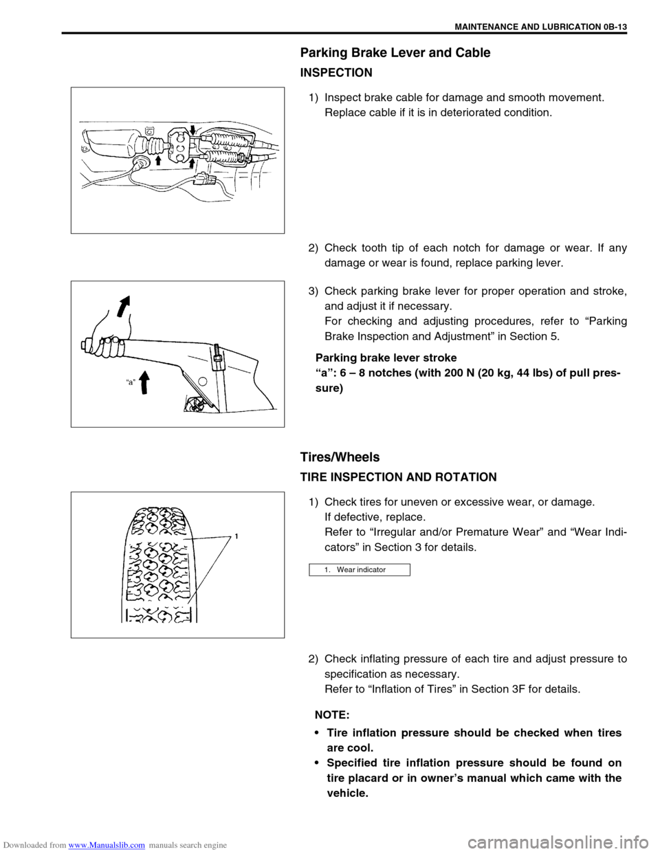
1) Inspect brake cable for damage and smooth movement.
Replace cable if it is in deteriorated condition.
2) Check tooth tip of each notch for damage or wear. If any
damage or wear is found, replace parking lever.
3) Check parking brake lever for proper operation and stroke,
and adjust it if necessary.
For checking and adjusting procedures, refer to “Parking
Brake Inspection and Adjustment” in Section 5.
Parking brake lever stroke
“a”: 6 – 8 notches (with 200 N (20 kg, 44 lbs) of pull pres-
sure)
Tires/Wheels
TIRE INSPECTION AND ROTATION
1) Check tires for uneven or excessive wear, or damage.
If defective, replace.
Refer to “Irregular and/or Premature Wear” and “Wear Indi-
cators” in Section 3 for details.
2) Check inflating pressure of each tire and adjust pressure to
specification as necessary.
Refer to “Inflation of Tires” in Section 3F for details.
1. Wear indicator
NOTE:
Tire inflation pressure should be checked when tires
are cool.
Specified tire inflation pressure should be found on
tire placard or in owner’s manual which came with the
vehicle.
Page 51 of 687

Downloaded from www.Manualslib.com manuals search engine 0B-20 MAINTENANCE AND LUBRICATION
Final Inspection
SEATS
Check that seat slides smoothly and locks securely at any position. Also check that reclining mechanism of front
seat back allows it to be locked at any angle.
SEAT BELT
Inspect belt system including webbing, buckles, latch plates, retractors and anchors for damage or wear.
If “REPLACE BELT” label on front seat belt is visible, replace belt. Check that seat belt is securely locked.
BATTERY ELECTROLYTE LEVEL CHECK
Check that the electrolyte level of all battery cells is between the upper and lower level lines on the case. If bat-
tery is equipped with built-in indicator, check battery condition by the indicator.
ACCELERATOR PEDAL OPERATION
Check that pedal operates smoothly without getting caught or interfered by any other part.
ENGINE START
Check engine start for readiness.
On automatic transmission vehicles, try to start the engine in each select lever position. The starting motor
should crank only in “P” (Park) or “N” (Neutral).
On manual transmission vehicles, place the shift lever in “Neutral,” depress clutch pedal fully any try to start.
EXHAUST SYSTEM CHECK
Check for leakage, cracks or loose supports.
CLUTCH (FOR MANUAL TRANSMISSION)
Check for the following.
Clutch is completely released when depressing clutch pedal,
No slipping clutch occurs when releasing pedal and accelerating.
Clutch itself is free from any abnormal condition. WARNING:
When carrying out road tests, select a safe place where no man or no running vehicle is seen so as to
prevent any accident.
WARNING:
Before performing the following check, be sure to have enough room around the vehicle. Then, firmly
apply both the parking brake and the regular brakes. Do not use the accelerator pedal. If the engine
starts, be ready to turn off the ignition promptly. Take these precautions because the vehicle could
move without warning and possibly cause personal injury or property damage.
Page 52 of 687

Downloaded from www.Manualslib.com manuals search engine MAINTENANCE AND LUBRICATION 0B-21
GEARSHIFT OR SELECTOR LEVER (TRANSMISSION)
Check gear shift or selector lever for smooth shifting to all positions and for good performance of transmission in
any position.
With automatic transmission equipped vehicle, also check that shift indicator indicates properly according to
which position selector lever is shifted to.
With automatic transmission equipped vehicle, make sure that vehicle is at complete stop when shifting selector
lever to “P” range position and release all brakes.
BRAKE
Foot Brake
Check the following:
that brake pedal has proper travel,
that brake works properly,
that it is free from noise,
that braking force is applied equally on all wheels,
and that brake do not drag.
Parking Brake
Check that lever has proper travel.
Check to ensure that parking brake is fully effective when the vehicle is stopped on the safe slope and brake
lever is pulled all the way.
STEERING
Check to ensure that steering wheel is free from instability, or abnormally heavy feeling.
Check that the vehicle does not wander or pull to one side.
ENGINE
Check that engine responds readily at all speeds.
Check that engine is free from abnormal noise and abnormal vibration.
BODY, WHEELS AND POWER TRANSMITTING SYSTEM
Check that body, wheels and power transmitting system are free from abnormal noise and abnormal vibration or
any other abnormal condition.
METERS AND GAUGE
Check that speedometer, odometer, fuel meter, temperature gauge, etc. are operating accurately.
LIGHTS
Check that all lights operate properly.
WINDSHIELD DEFROSTER
Periodically check that air comes out from defroster outlet when operating heater or air conditioning.
Set mode control lever to defroster position and fan switch lever to “HI” position for this check. WARNING:
With vehicle parked on a fairly steep slope, make sure nothing is in the way downhill to avoid any per-
sonal injury or property damage. Be prepared to apply regular brake quickly even if vehicle should
start to move.
Page 53 of 687

Downloaded from www.Manualslib.com manuals search engine 0B-22 MAINTENANCE AND LUBRICATION
Recommended Fluids and Lubricants
Engine oilSE, SF, SG, SH, SJ or SL
(Refer to “Engine Oil and Oil Filter” in this section for engine oil viscos-
ity.)
Engine coolant
(Ethylene glycol base coolant)“Antifreeze/Anticorrosion coolant”
Brake fluid DOT 3
Manual transmission oil Refer to “Maintenance Service” in Section 7A.
Transfer oil Refer to “Oil Change” in Section 7D.
Differential oil (front & rear) Refer to “Oil Change” in Section 7E and 7F.
Automatic transmission fluid
An equivalent of DEXRON
®-IIE or DEXRON®-III
Power steering fluid
An equivalent of DEXRON
®-II, DEXRON®-IIE or DEXRON®-III
Clutch linkage pivot points
Water resistance chassis grease
(SUZUKI SUPER GREASE A 99000-25010)
Steering knuckle seal
Door hinges
Engine oil or water resistance chassis grease
Hood latch assembly
Key lock cylinder Spray lubricant
Page 111 of 687

Downloaded from www.Manualslib.com manuals search engine 3-2 STEERING, SUSPENSION, WHEELS AND TIRES
General Diagnosis
Since the problems in steering, suspension, wheels and tires involve several systems, they must all be consid-
ered when diagnosing a complaint. To avoid using the wrong symptom, always road test the vehicle first.
Proceed with the following preliminary inspections and correct any defects which are found.
1) Inspect tires for proper pressure and uneven wear.
2) Raise vehicle on a hoist and inspect front and rear suspension and steering system for loose or damaged
parts.
3) Spin front wheel. Inspect for out-of-round tires, out-of-balance tires, bent rims, loose and/or rough wheel
bearings.
Diagnosis Table
Condition Possible Cause Correction
Vehicle Pulls (Leads)
Mismatched or uneven tires Replace tire.
Tires not adequately inflated Adjust tire pressure.
Broken or sagging springs Replace spring.
Radial tire lateral force Replace tire.
Disturbed front wheel alignment Check and adjust wheel alignment.
Disturbed rear wheel alignment Check and adjust wheel alignment.
Brake dragging in one road wheel Repair front brake.
Loose, bent or broken front or rear suspension
partsTighten or replace suspension part.
Abnormal or
Excessive Tire WearSagging or broken springs Replace spring.
Tire out of balance Adjust balance or replace tire.
Disturbed front wheel alignment Check wheel alignment.
Faulty shock absorber Replace shock absorber.
Hard driving Replace tire.
Overloaded vehicle Replace tire.
Not rotating tire Replace or rotate tire.
Worn or loose road wheel bearings Replace wheel bearing.
Wobbly wheel or tires Replace wheel or tire.
Tires not adequately inflated Adjust the pressure.
Wheel Tramp
Blister or bump on tire Replace tire.
Improper shock absorber action Replace shock absorber.
Page 113 of 687

Downloaded from www.Manualslib.com manuals search engine 3-4 STEERING, SUSPENSION, WHEELS AND TIRES
Abnormal Noise,
Front EndWorn, sticky or loose tie rod ends, drug rod ball
joints, king pin bearings or axle shaft jointsReplace tie rod end, king pin bear-
ing or axle shaft joint.
Damaged shock absorbers or mountings Replace or repair.
Worn leading arm bushings Replace.
Worn stabilizer bar bushings Replace.
Worn Iateral rod bushings Replace.
Loose stabilizer bar Tighten bolts or replace bushes.
Loose wheel nuts Tighten wheel nuts.
Loose suspension bolts or nuts Tighten suspension bolts or nuts.
Broken or otherwise damaged wheel bearings Replace wheel bearing.
Broken suspension springs Replace spring.
Wander or Poor
Steering StabilityMismatched or uneven tires Replace tire or inflate tires to
proper pressure.
Loose king pin bearings and tie rod ends Replace king pin bearing or tie rod
end.
Faulty shock absorbers or mounting Replace absorber or repair mount-
ing.
Loose stabilizer bar Tighten or replace stabilizer bar or
bushes.
Broken or sagging springs Replace spring.
Steering gear box not properly adjusted Check or adjust steering gear box
torque.
Front wheel alignment Check and adjust front wheel align-
ment.
Erratic Steering when
BrakingWorn wheel bearings Replace wheel bearing.
Broken or sagging springs Replace spring.
Leaking wheel cylinder or caliper Repair or replace wheel cylinder or
caliper.
Warped discs Replace brake disc.
Badly worn brake linings Replace brake shoe lining.
Drum is out of round in some brakes Replace brake drum.
Wheel tires are inflated unequally Inflate tires to proper pressure.
Defective wheel cylinders Replace or repair wheel cylinder.
Disturbed front wheel alignment Check front wheel alignment
Ride Too Soft
Faulty shock absorber Replace shock absorber.
Suspension bottoms
Overloaded Check loading.
Faulty shocks absorber Replace shock absorber.
Incorrect, broken or sagging springs Replace spring.
Body Leans or Sways
in CornersLoose stabilizer bar Tighten stabilizer bar bolts or
replace bushes.
Faulty shocks absorbers or mounting Replace shock absorber or tighten
mounting.
Broken or sagging springs Replace spring.
Overloaded Check loading.
Cupped Tires
Worn wheel bearings Replace wheel bearing.
Excessive tire or wheel run-out Replace tire or wheel disc.
Tire out of balance Adjust tire balance. Condition Possible Cause Correction
Page 116 of 687

Downloaded from www.Manualslib.com manuals search engine STEERING, SUSPENSION, WHEELS AND TIRES 3-7
Radial Tire Lead
“Lead” is the deviation of the vehicle from a straight path on a level rod even with no pressure on the steering
wheel.
Lead is usually caused by:
1) Incorrect alignment.
2) Uneven brake adjustment.
3) Tire construction.
The way in which a tire is built can produce lead in a vehicle. An example of this is placement of the belt. Off
center belts on radial tires can cause the tire to develop a side force while rolling straight down the road. If one
side of the tire has a little larger diameter than the other, the tire will tend to roll to one side. This will develop a
side force which can produce vehicle lead.
The procedure in above figure (Lead Diagnosis) should be used to make sure that front alignment is not mis-
taken for tire lead.
1) Part of the lead diagnosis procedure is different from the proper tire rotation pattern currently in the owner
and service manuals. If a medium to high mileage tire is moved to the other side of the vehicle, be sure to
check that ride roughness has not developed.
2) Rear tires will not cause lead.
Vibration Diagnosis
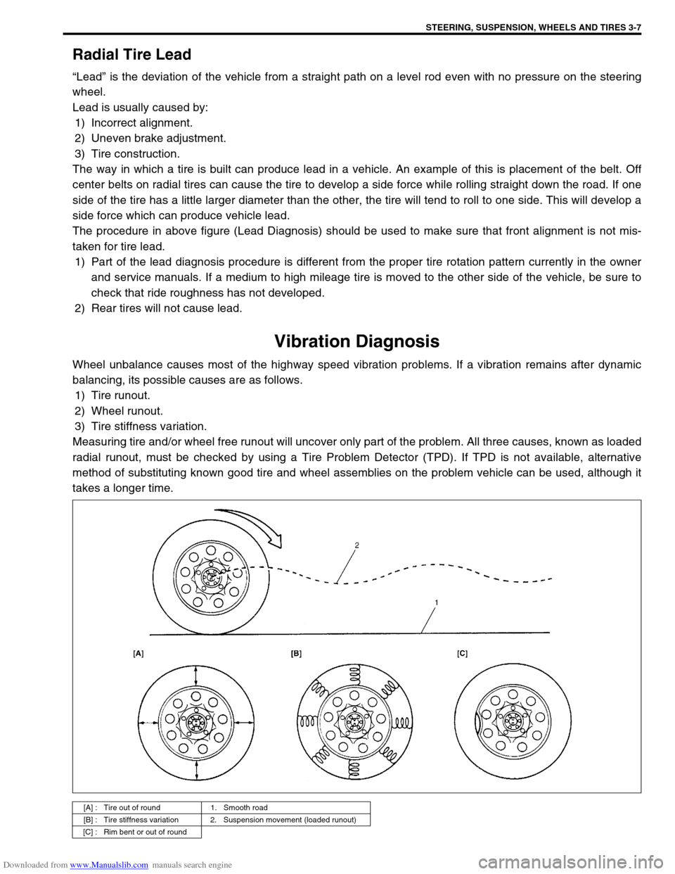
Wheel unbalance causes most of the highway speed vibration problems. If a vibration remains after dynamic
balancing, its possible causes are as follows.
1) Tire runout.
2) Wheel runout.
3) Tire stiffness variation.
Measuring tire and/or wheel free runout will uncover only part of the problem. All three causes, known as loaded
radial runout, must be checked by using a Tire Problem Detector (TPD). If TPD is not available, alternative
method of substituting known good tire and wheel assemblies on the problem vehicle can be used, although it
takes a longer time.
[A] : Tire out of round 1. Smooth road
[B] : Tire stiffness variation 2. Suspension movement (loaded runout)
[C] : Rim bent or out of round
Page 192 of 687

Downloaded from www.Manualslib.com manuals search engine FRONT SUSPENSION 3D-19
Front Shock Absorber
REMOVAL
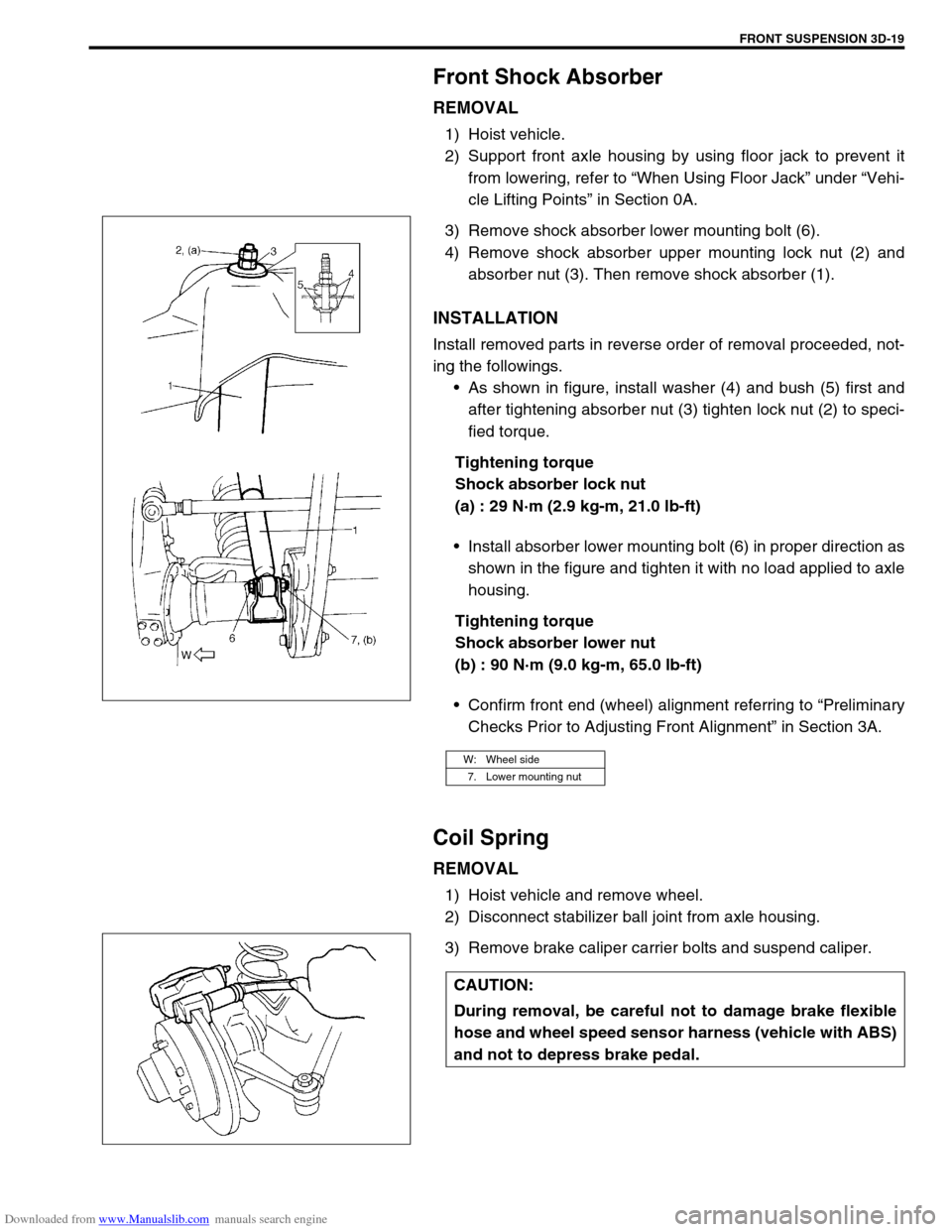
1) Hoist vehicle.
2) Support front axle housing by using floor jack to prevent it
from lowering, refer to “When Using Floor Jack” under “Vehi-
cle Lifting Points” in Section 0A.
3) Remove shock absorber lower mounting bolt (6).
4) Remove shock absorber upper mounting lock nut (2) and
absorber nut (3). Then remove shock absorber (1).
INSTALLATION
Install removed parts in reverse order of removal proceeded, not-
ing the followings.
As shown in figure, install washer (4) and bush (5) first and
after tightening absorber nut (3) tighten lock nut (2) to speci-
fied torque.
Tightening torque
Shock absorber lock nut
(a) : 29 N·m (2.9 kg-m, 21.0 lb-ft)
Install absorber lower mounting bolt (6) in proper direction as
shown in the figure and tighten it with no load applied to axle
housing.
Tightening torque
Shock absorber lower nut
(b) : 90 N·m (9.0 kg-m, 65.0 lb-ft)
Confirm front end (wheel) alignment referring to “Preliminary
Checks Prior to Adjusting Front Alignment” in Section 3A.
Coil Spring
REMOVAL
1) Hoist vehicle and remove wheel.
2) Disconnect stabilizer ball joint from axle housing.
3) Remove brake caliper carrier bolts and suspend caliper.
W: Wheel side
7. Lower mounting nut
CAUTION:
During removal, be careful not to damage brake flexible
hose and wheel speed sensor harness (vehicle with ABS)
and not to depress brake pedal.
Page 193 of 687

Downloaded from www.Manualslib.com manuals search engine 3D-20 FRONT SUSPENSION
4) Support front axle housing by using floor jack.
5) Remove shock absorber lower mounting bolt (1).
6) Lower front axle housing (2) gradually as far down as where
coil spring (1) can be removed.
7) Remove coil spring (1).
INSTALLATION
Install removed parts in reverse order of removal procedures, not-
ing the followings.
1) Install coil spring (3).
2) Install absorber lower mounting bolt, refer to “Front Shock
Absorber” in this section.
3) Install caliper assembly and tighten caliper bolts to specified
torque.
Tightening torque
Brake caliper carrier bolts
(a) : 85 N·m (8.5 kg-m, 61.5 lb-ft)
4) Connect stabilizer ball joint to axle housing and tighten nut
referring to “Stabilizer Bar” in this section for tightening
torque specification. NOTE:
When supporting axle housing, it should be in non-load
condition.
NOTE:
Make sure that coil spring direction as shown.
When seating coil spring, mate spring end with
stepped part (4) of lower spring seat (2).
1. Front axle housing
U : Upper side
A : Small
B : Large
Page 194 of 687

Downloaded from www.Manualslib.com manuals search engine FRONT SUSPENSION 3D-21
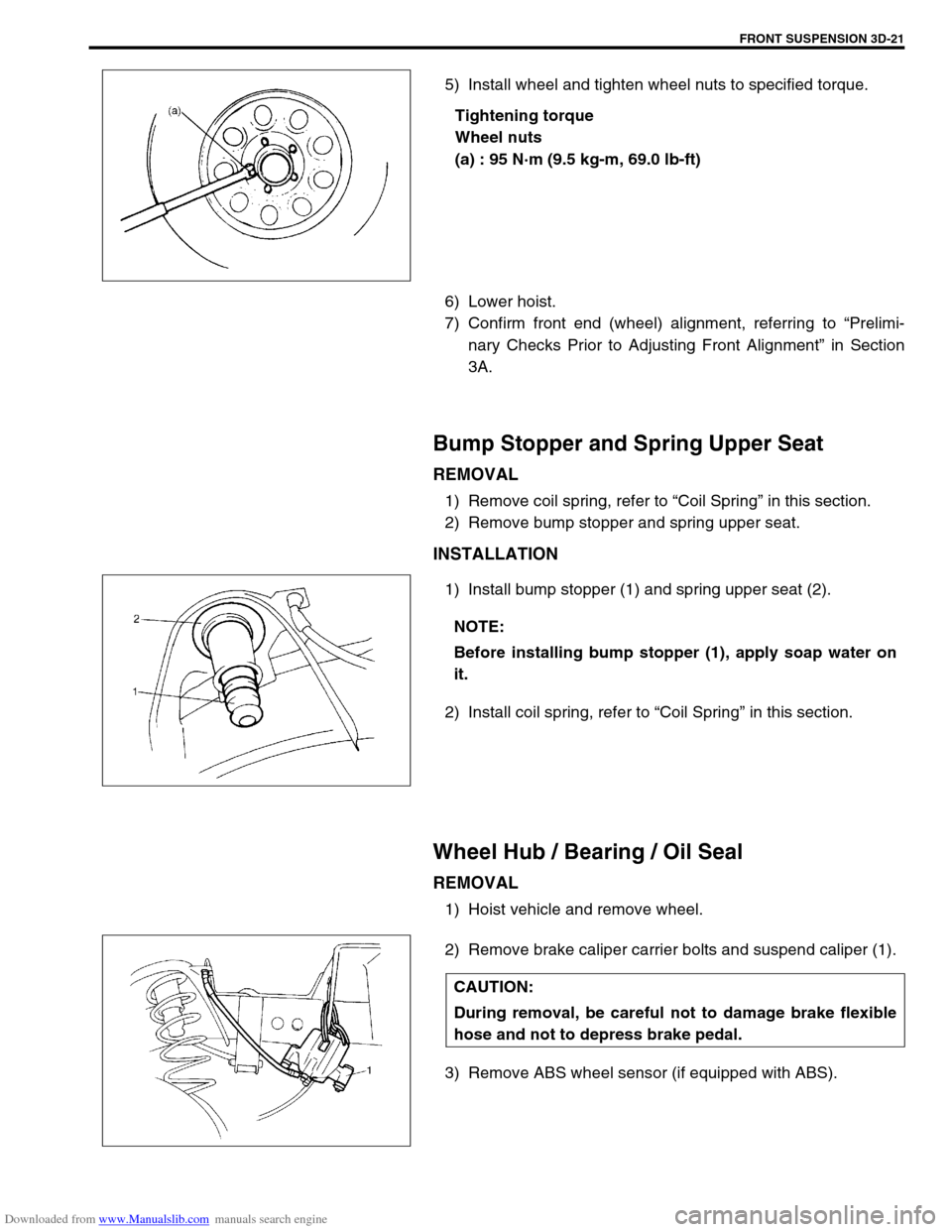
5) Install wheel and tighten wheel nuts to specified torque.
Tightening torque
Wheel nuts
(a) : 95 N·m (9.5 kg-m, 69.0 lb-ft)
6) Lower hoist.
7) Confirm front end (wheel) alignment, referring to “Prelimi-
nary Checks Prior to Adjusting Front Alignment” in Section
3A.
Bump Stopper and Spring Upper Seat
REMOVAL
1) Remove coil spring, refer to “Coil Spring” in this section.
2) Remove bump stopper and spring upper seat.
INSTALLATION
1) Install bump stopper (1) and spring upper seat (2).
2) Install coil spring, refer to “Coil Spring” in this section.
Wheel Hub / Bearing / Oil Seal
REMOVAL
1) Hoist vehicle and remove wheel.
2) Remove brake caliper carrier bolts and suspend caliper (1).
3) Remove ABS wheel sensor (if equipped with ABS).
NOTE:
Before installing bump stopper (1), apply soap water on
it.
CAUTION:
During removal, be careful not to damage brake flexible
hose and not to depress brake pedal.