Connector SUZUKI JIMNY 2005 3.G Service User Guide
[x] Cancel search | Manufacturer: SUZUKI, Model Year: 2005, Model line: JIMNY, Model: SUZUKI JIMNY 2005 3.GPages: 687, PDF Size: 13.38 MB
Page 21 of 687
Downloaded from www.Manualslib.com manuals search engine 0A-16 GENERAL INFORMATION
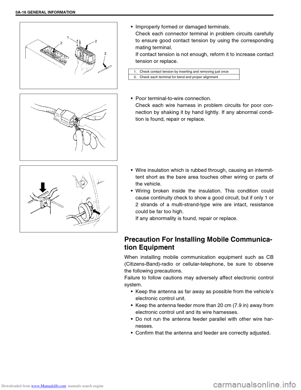
Improperly formed or damaged terminals.
Check each connector terminal in problem circuits carefully
to ensure good contact tension by using the corresponding
mating terminal.
If contact tension is not enough, reform it to increase contact
tension or replace.
Poor terminal-to-wire connection.
Check each wire harness in problem circuits for poor con-
nection by shaking it by hand lightly. If any abnormal condi-
tion is found, repair or replace.
Wire insulation which is rubbed through, causing an intermit-
tent short as the bare area touches other wiring or parts of
the vehicle.
Wiring broken inside the insulation. This condition could
cause continuity check to show a good circuit, but if only 1 or
2 strands of a multi-strand-type wire are intact, resistance
could be far too high.
If any abnormality is found, repair or replace.
Precaution For Installing Mobile Communica-
tion Equipment
When installing mobile communication equipment such as CB
(Citizens-Band)-radio or cellular-telephone, be sure to observe
the following precautions.
Failure to follow cautions may adversely affect electronic control
system.
Keep the antenna as far away as possible from the vehicle’s
electronic control unit.
Keep the antenna feeder more than 20 cm (7.9 in) away from
electronic control unit and its wire harnesses.
Do not run the antenna feeder parallel with other wire har-
nesses.
Confirm that the antenna and feeder are correctly adjusted.
1. Check contact tension by inserting and removing just once
2. Check each terminal for bend and proper alignment
Page 26 of 687

Downloaded from www.Manualslib.com manuals search engine GENERAL INFORMATION 0A-21
Abbreviations May Be Used In This Manual
Abbreviations
AABC
ATDC
API
ATF
ALR
AC
A/T
A/C
ABDC
A/F
A-ELRAnti-lock Brake System
After Top Dead Center
American Petroleum Institute
Automatic Transmission Fluid
Automatic Locking Retractor
Alternating Current
Automatic Transmission
Air Conditioning
After Bottom Dead Center
Air Fuel Mixture Ratio
Automatic-Emergency
Locking RetractorEEBCM
ECM
ECT Sensor
EGR
EGRT Sensor
EFE Heater
ELR
EPS
EVAP
EVAP CanisterElectronic Brake Control Module,
ABS Control Module
Engine Control Module
Engine Coolant Temperature
Sensor (Water Temp. Sensor,
WTS)
Exhaust Gas Recirculation
EGR Temperature Sensor
(Recirculated Exhaust Gas Temp.
Sensor, REGTS)
Early Fuel Evaporation
Heater (Positive Temperature
Coefficient, PTC Heater)
Emergency Locking Retractor
Electronic Power Steering
Evaporative Emission
Evaporative Emission Canister
(Charcoal Canister) BB+
BTDC
BBDCBattery Positive Voltage
Before Top Dead Center
Before Bottom Dead Center
CCKT
CMP Sensor
CO
CPP Switch
CPU
CRSCircuit
Camshaft Position Sensor
(Crank Angle Sensor, CAS)
Carbon Monoxide
Clutch Pedal Position Switch
(Clutch Switch, Clutch Start
Switch)
Central Processing Unit
Child Restraint SystemF 4WD 4 Wheel Drive
GGEN
GNDGenerator
Ground
HHC
HO2SHydrocarbons
Heated Oxygen Sensor
DDC
DLC
DOHC
DOJ
DRL
DTCDirect Current
Data Link Connector
(Assembly Line Diag. Link, ALDL,
Serial Data Link, SDL)
Double Over Head Camshaft
Double Offset Joint
Daytime Running Light
Diagnostic Trouble Code
(Diagnostic Code)IIAC Valve
IAT Sensor
ICM
IG
ISC ActuatorIdle Air Control Valve (Idle Speed
Control Solenoid Valve, ISC
Solenoid Valve)
Intake Air Temperature Sensor
(Air temperature Sensor, ATS)
Immobilizer Control Module
Ignition
Idle Speed Control Actuator
(Motor)
Page 92 of 687
Downloaded from www.Manualslib.com manuals search engine AIR CONDITIONING (OPTIONAL) 1B-31
Condenser Assembly
INSPECTION
Check the following.
Check clog of condenser fins.
If, any clogs are found, condenser fins should be washed
with water, and should be dried with compressed air.
Check condenser fins for leakage and breakage.
If any defects are found, repair or replace condenser.
Check condenser fittings for leakage.
If any defects are found, repair or replace condenser.
REMOVAL
1) Disconnect negative (–) cable at battery.
2) Recover refrigerant from A/C system by referring to “Recov-
ery” in this section.
3) Remove front bumper referring to “Front Bumper” in Section
8.
4) Disconnect A/C condenser cooling fan motor and dual pres-
sure switch connectors.
5) Remove radiator mounting bolts.
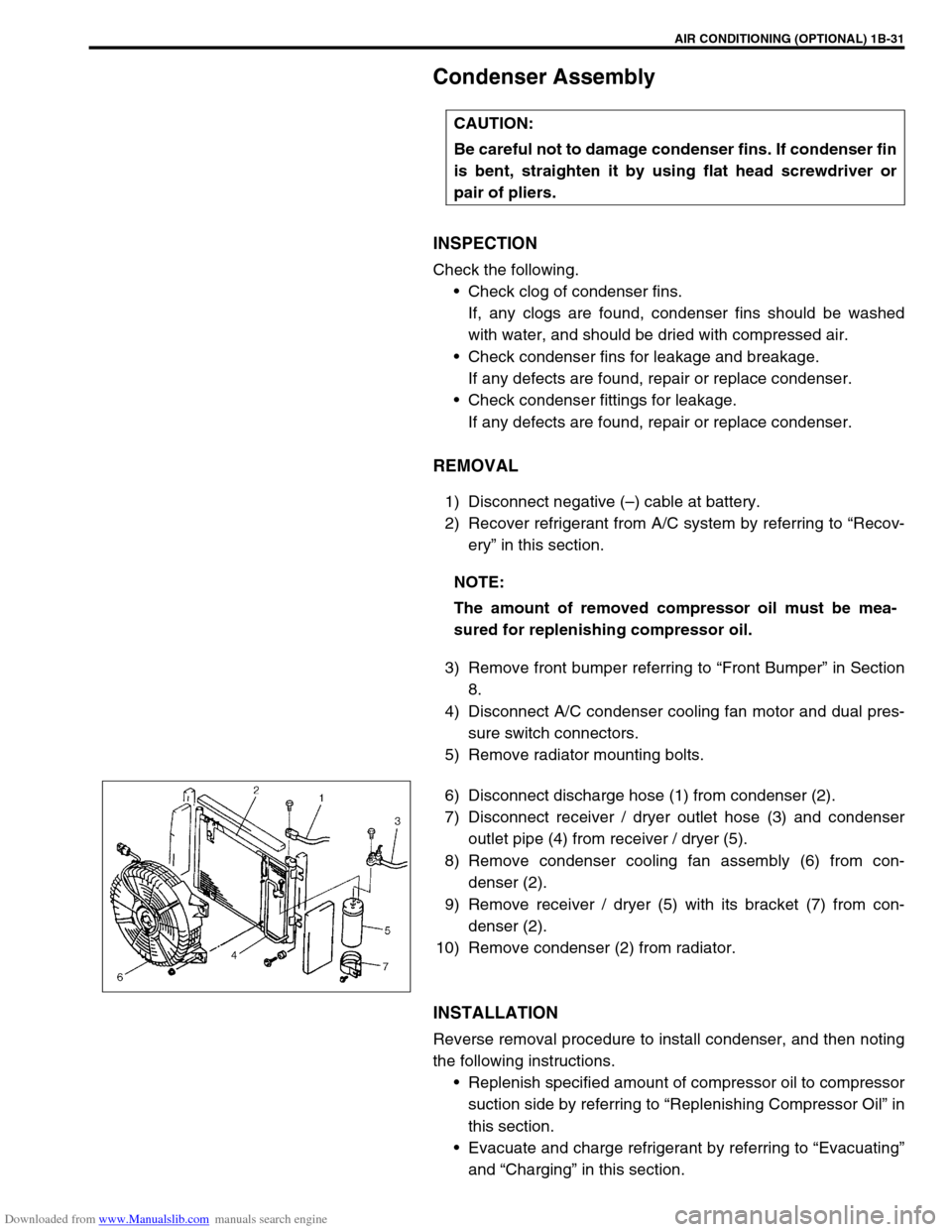
6) Disconnect discharge hose (1) from condenser (2).
7) Disconnect receiver / dryer outlet hose (3) and condenser
outlet pipe (4) from receiver / dryer (5).
8) Remove condenser cooling fan assembly (6) from con-
denser (2).
9) Remove receiver / dryer (5) with its bracket (7) from con-
denser (2).
10) Remove condenser (2) from radiator.
INSTALLATION
Reverse removal procedure to install condenser, and then noting
the following instructions.
Replenish specified amount of compressor oil to compressor
suction side by referring to “Replenishing Compressor Oil” in
this section.
Evacuate and charge refrigerant by referring to “Evacuating”
and “Charging” in this section. CAUTION:
Be careful not to damage condenser fins. If condenser fin
is bent, straighten it by using flat head screwdriver or
pair of pliers.
NOTE:
The amount of removed compressor oil must be mea-
sured for replenishing compressor oil.
Page 94 of 687
Downloaded from www.Manualslib.com manuals search engine AIR CONDITIONING (OPTIONAL) 1B-33
Condenser Cooling Fan Assembly
ASSEMBLY
INSPECTION
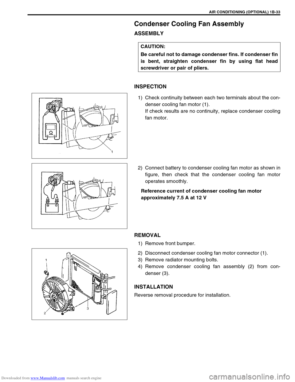
1) Check continuity between each two terminals about the con-
denser cooling fan motor (1).
If check results are no continuity, replace condenser cooling
fan motor.
2) Connect battery to condenser cooling fan motor as shown in
figure, then check that the condenser cooling fan motor
operates smoothly.
Reference current of condenser cooling fan motor
approximately 7.5 A at 12 V
REMOVAL
1) Remove front bumper.
2) Disconnect condenser cooling fan motor connector (1).
3) Remove radiator mounting bolts.
4) Remove condenser cooling fan assembly (2) from con-
denser (3).
INSTALLATION
Reverse removal procedure for installation.CAUTION:
Be careful not to damage condenser fins. If condenser fin
is bent, straighten condenser fin by using flat head
screwdriver or pair of pliers.
Page 101 of 687
Downloaded from www.Manualslib.com manuals search engine 1B-40 AIR CONDITIONING (OPTIONAL)
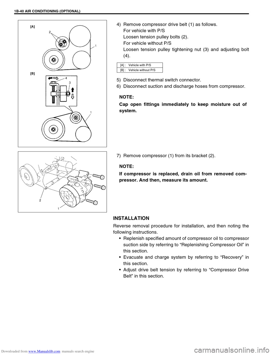
4) Remove compressor drive belt (1) as follows.
For vehicle with P/S
Loosen tension pulley bolts (2).
For vehicle without P/S
Loosen tension pulley tightening nut (3) and adjusting bolt
(4).
5) Disconnect thermal switch connector.
6) Disconnect suction and discharge hoses from compressor.
7) Remove compressor (1) from its bracket (2).
INSTALLATION
Reverse removal procedure for installation, and then noting the
following instructions.
Replenish specified amount of compressor oil to compressor
suction side by referring to “Replenishing Compressor Oil” in
this section.
Evacuate and charge system by referring to “Recovery” in
this section.
Adjust drive belt tension by referring to “Compressor Drive
Belt” in this section.
[A] : Vehicle with P/S
[B] : Vehicle without P/S
NOTE:
Cap open fittings immediately to keep moisture out of
system.
NOTE:
If compressor is replaced, drain oil from removed com-
pressor. And then, measure its amount.
Page 138 of 687
Downloaded from www.Manualslib.com manuals search engine POWER STEERING (P/S) SYSTEM (If equipped) 3B1-7
Idle-Up System Check
1) Warm up engine to normal operating temperature.
2) Turn A/C switch OFF, if equipped.
3) Turn steering wheel fully and check idle speed.
Engine idle speed drops a little momentarily when steering wheel is turned fully but returns to its specified
level immediately. If power steering pressure switch connector is connected, check the same with that con-
nector disconnected. Momentary drop of engine idle speed should be less when it is connected than when
disconnected.
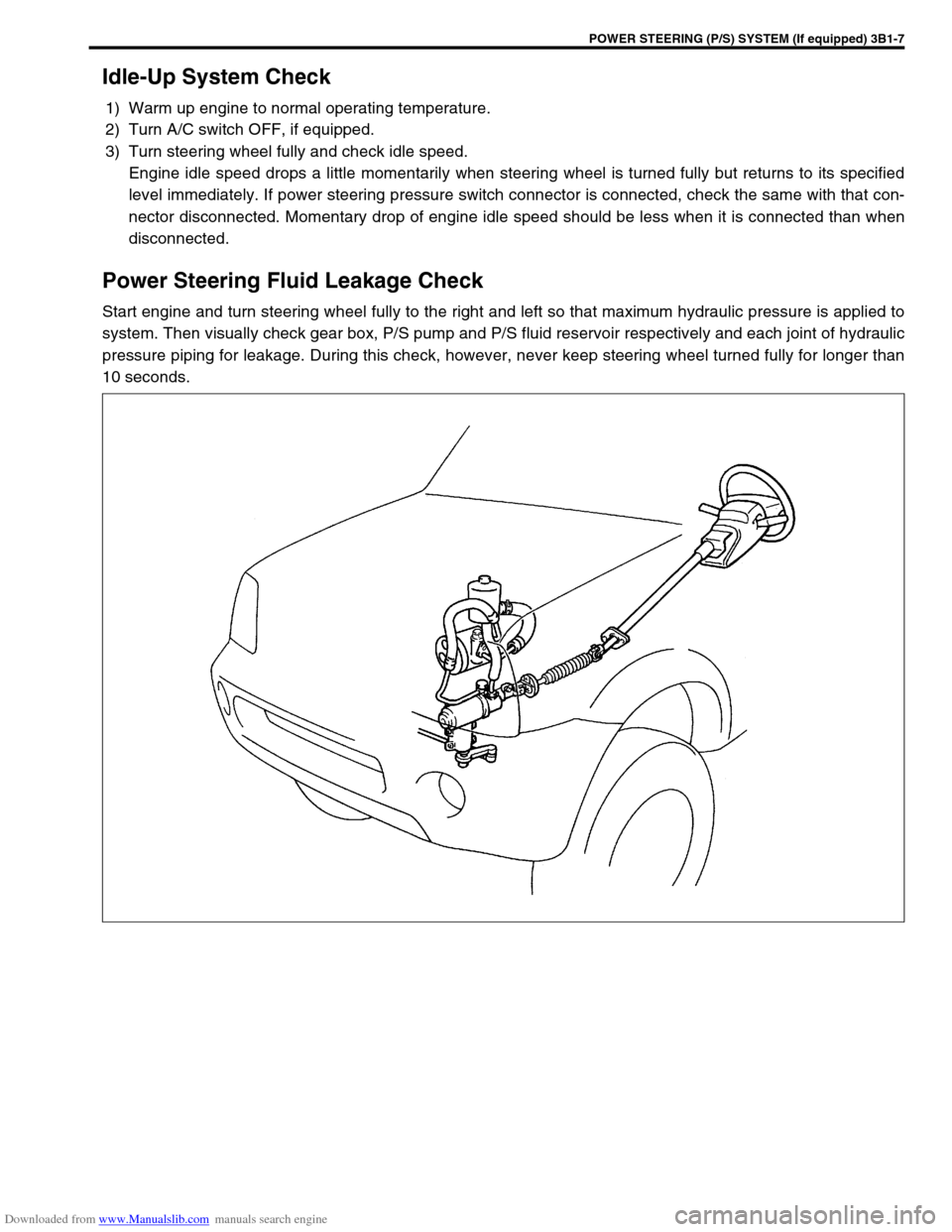
Power Steering Fluid Leakage Check
Start engine and turn steering wheel fully to the right and left so that maximum hydraulic pressure is applied to
system. Then visually check gear box, P/S pump and P/S fluid reservoir respectively and each joint of hydraulic
pressure piping for leakage. During this check, however, never keep steering wheel turned fully for longer than
10 seconds.
Page 141 of 687
Downloaded from www.Manualslib.com manuals search engine 3B1-10 POWER STEERING (P/S) SYSTEM (If equipped)
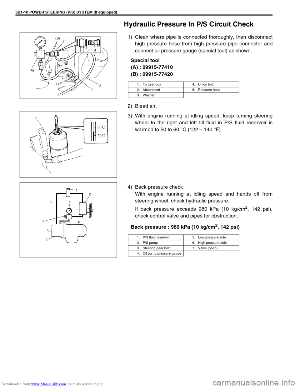
Hydraulic Pressure In P/S Circuit Check
1) Clean where pipe is connected thoroughly, then disconnect
high pressure hose from high pressure pipe connector and
connect oil pressure gauge (special tool) as shown.
Special tool
(A) : 09915-77410
(B) : 09915-77420
2) Bleed air.
3) With engine running at idling speed, keep turning steering
wheel to the right and left till fluid in P/S fluid reservoir is
warmed to 50 to 60 °C (122 – 140 °F)
4) Back pressure check
With engine running at idling speed and hands off from
steering wheel, check hydraulic pressure.
If back pressure exceeds 980 kPa (10 kg/cm
2, 142 psi),
check control valve and pipes for obstruction.
Back pressure : 980 kPa (10 kg/cm
2, 142 psi)
1. To gear box 4. Union bolt
2. Attachment 5. Pressure hose
3. Washer
1. P/S fluid reservoir 5. Low pressure side
2. P/S pump 6. High pressure side
3. Steering gear box 7. Valve (open)
4. Oil pump pressure gauge
Page 144 of 687
Downloaded from www.Manualslib.com manuals search engine POWER STEERING (P/S) SYSTEM (If equipped) 3B1-13
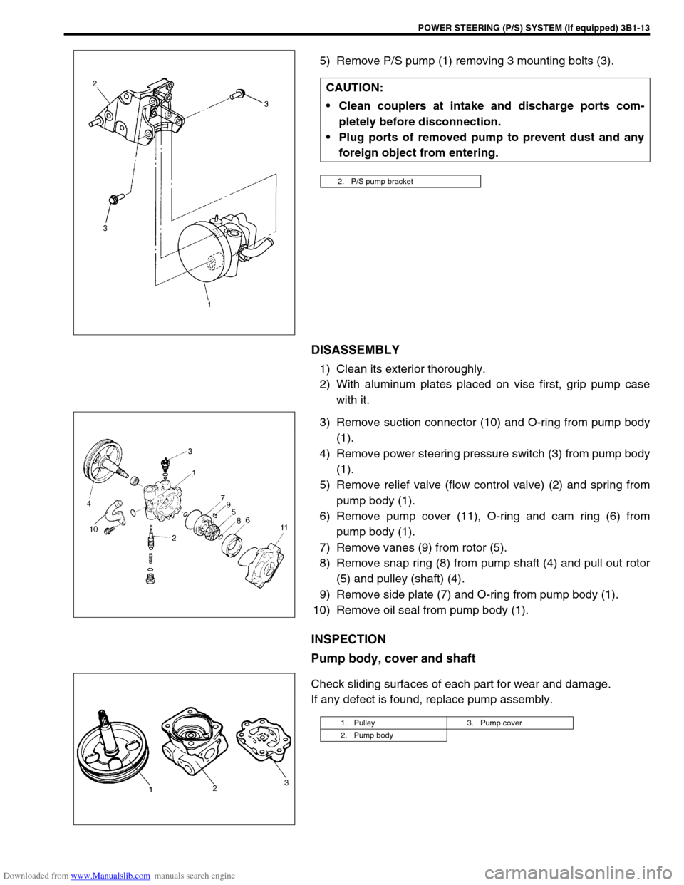
5) Remove P/S pump (1) removing 3 mounting bolts (3).
DISASSEMBLY
1) Clean its exterior thoroughly.
2) With aluminum plates placed on vise first, grip pump case
with it.
3) Remove suction connector (10) and O-ring from pump body
(1).
4) Remove power steering pressure switch (3) from pump body
(1).
5) Remove relief valve (flow control valve) (2) and spring from
pump body (1).
6) Remove pump cover (11), O-ring and cam ring (6) from
pump body (1).
7) Remove vanes (9) from rotor (5).
8) Remove snap ring (8) from pump shaft (4) and pull out rotor
(5) and pulley (shaft) (4).
9) Remove side plate (7) and O-ring from pump body (1).
10) Remove oil seal from pump body (1).
INSPECTION
Pump body, cover and shaft
Check sliding surfaces of each part for wear and damage.
If any defect is found, replace pump assembly.CAUTION:
Clean couplers at intake and discharge ports com-
pletely before disconnection.
Plug ports of removed pump to prevent dust and any
foreign object from entering.
2. P/S pump bracket
1. Pulley 3. Pump cover
2. Pump body
Page 145 of 687
Downloaded from www.Manualslib.com manuals search engine 3B1-14 POWER STEERING (P/S) SYSTEM (If equipped)
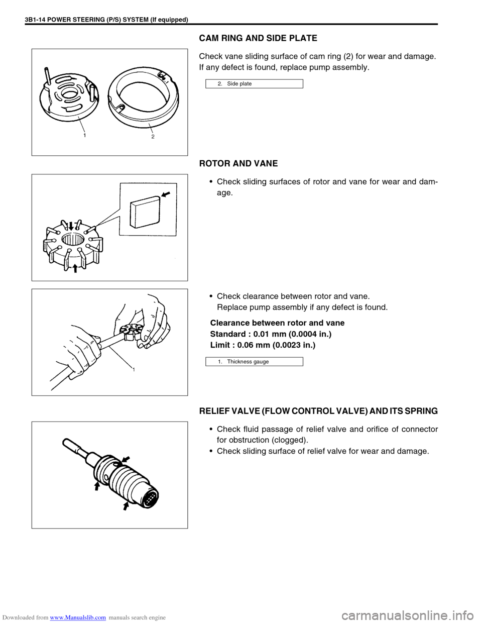
CAM RING AND SIDE PLATE
Check vane sliding surface of cam ring (2) for wear and damage.
If any defect is found, replace pump assembly.
ROTOR AND VANE
Check sliding surfaces of rotor and vane for wear and dam-
age.
Check clearance between rotor and vane.
Replace pump assembly if any defect is found.
Clearance between rotor and vane
Standard : 0.01 mm (0.0004 in.)
Limit : 0.06 mm (0.0023 in.)
RELIEF VALVE (FLOW CONTROL VALVE) AND ITS SPRING
Check fluid passage of relief valve and orifice of connector
for obstruction (clogged).
Check sliding surface of relief valve for wear and damage.
2. Side plate
1. Thickness gauge
Page 148 of 687
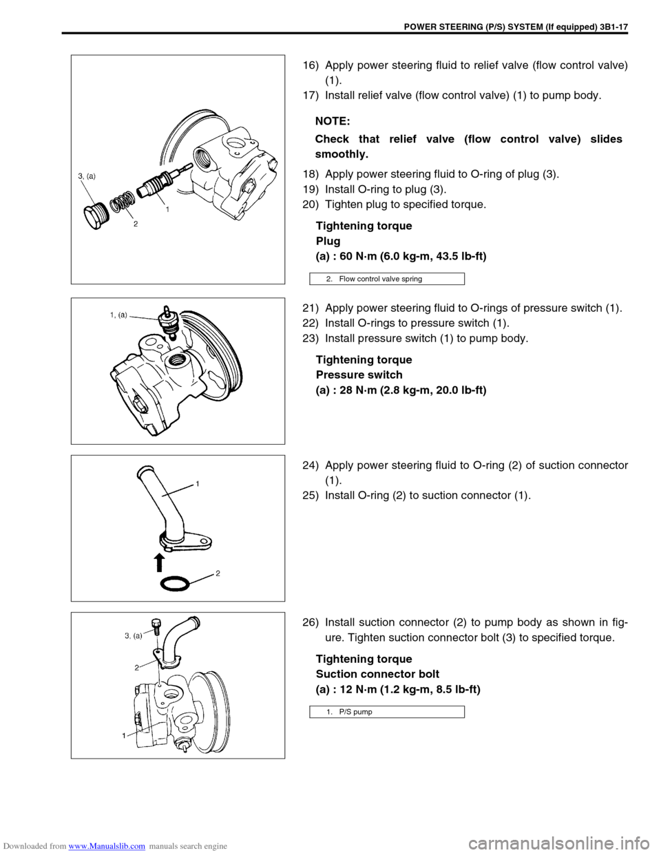
Downloaded from www.Manualslib.com manuals search engine POWER STEERING (P/S) SYSTEM (If equipped) 3B1-17
16) Apply power steering fluid to relief valve (flow control valve)
(1).
17) Install relief valve (flow control valve) (1) to pump body.
18) Apply power steering fluid to O-ring of plug (3).
19) Install O-ring to plug (3).
20) Tighten plug to specified torque.
Tightening torque
Plug
(a) : 60 N·m (6.0 kg-m, 43.5 lb-ft)
21) Apply power steering fluid to O-rings of pressure switch (1).
22) Install O-rings to pressure switch (1).
23) Install pressure switch (1) to pump body.
Tightening torque
Pressure switch
(a) : 28 N·m (2.8 kg-m, 20.0 lb-ft)
24) Apply power steering fluid to O-ring (2) of suction connector
(1).
25) Install O-ring (2) to suction connector (1).
26) Install suction connector (2) to pump body as shown in fig-
ure. Tighten suction connector bolt (3) to specified torque.
Tightening torque
Suction connector bolt
(a) : 12 N·m (1.2 kg-m, 8.5 lb-ft) NOTE:
Check that relief valve (flow control valve) slides
smoothly.
2. Flow control valve spring
1. P/S pump