fuse SUZUKI JIMNY 2005 3.G Service Workshop Manual
[x] Cancel search | Manufacturer: SUZUKI, Model Year: 2005, Model line: JIMNY, Model: SUZUKI JIMNY 2005 3.GPages: 687, PDF Size: 13.38 MB
Page 9 of 687
Downloaded from www.Manualslib.com manuals search engine 0A-4 GENERAL INFORMATION
Servicing and handling
WARNING:
Many of service procedures require disconnection of “Air
Bag” fuse and all air bag (inflator) module(s) from initia-
tor circuit to avoid an accidental deployment.
Driver and Passenger Air Bag (Inflator) Modules
For handling and storage of a live air bag (inflator)
module, select a place where the ambient temperature
below 65°C (150°F), without high humidity and away
from electric noise.
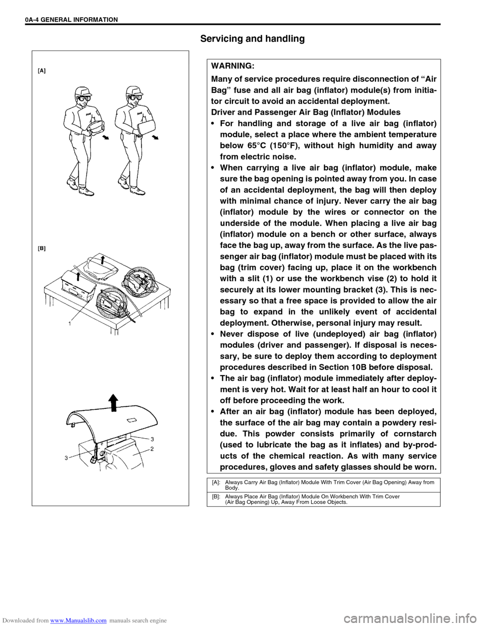
When carrying a live air bag (inflator) module, make
sure the bag opening is pointed away from you. In case
of an accidental deployment, the bag will then deploy
with minimal chance of injury. Never carry the air bag
(inflator) module by the wires or connector on the
underside of the module. When placing a live air bag
(inflator) module on a bench or other surface, always
face the bag up, away from the surface. As the live pas-
senger air bag (inflator) module must be placed with its
bag (trim cover) facing up, place it on the workbench
with a slit (1) or use the workbench vise (2) to hold it
securely at its lower mounting bracket (3). This is nec-
essary so that a free space is provided to allow the air
bag to expand in the unlikely event of accidental
deployment. Otherwise, personal injury may result.
Never dispose of live (undeployed) air bag (inflator)
modules (driver and passenger). If disposal is neces-
sary, be sure to deploy them according to deployment
procedures described in Section 10B before disposal.
The air bag (inflator) module immediately after deploy-
ment is very hot. Wait for at least half an hour to cool it
off before proceeding the work.
After an air bag (inflator) module has been deployed,
the surface of the air bag may contain a powdery resi-
due. This powder consists primarily of cornstarch
(used to lubricate the bag as it inflates) and by-prod-
ucts of the chemical reaction. As with many service
procedures, gloves and safety glasses should be worn.
[A]: Always Carry Air Bag (Inflator) Module With Trim Cover (Air Bag Opening) Away from
Body.
[B]: Always Place Air Bag (Inflator) Module On Workbench With Trim Cover
(Air Bag Opening) Up, Away From Loose Objects.
Page 15 of 687
Downloaded from www.Manualslib.com manuals search engine 0A-10 GENERAL INFORMATION
Precautions For Catalytic Converter
For vehicles equipped with a catalytic converter, use only unleaded gasoline and be careful not to let a
large amount of unburned gasoline enter the converter or it can be damaged.
Conduct a spark jump test only when necessary, make it as short as possible, and do not open the
throttle.
Conduct engine compression checks within the shortest possible time.
Avoid situations which can result in engine misfire (e.g. starting the engine when the fuel tank is
nearly empty.)
Precautions For Electrical Circuit Service
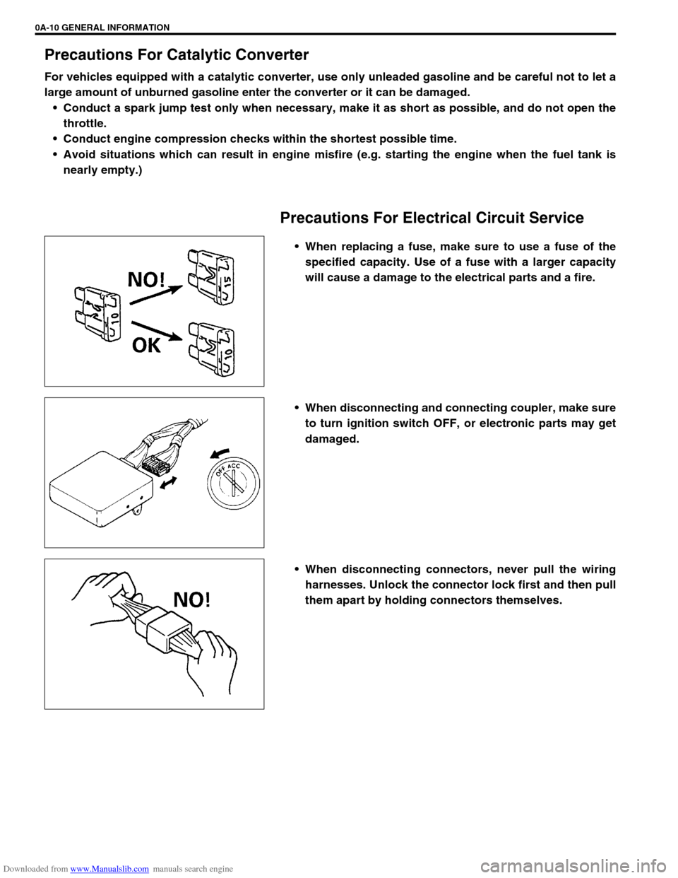
When replacing a fuse, make sure to use a fuse of the
specified capacity. Use of a fuse with a larger capacity
will cause a damage to the electrical parts and a fire.
When disconnecting and connecting coupler, make sure
to turn ignition switch OFF, or electronic parts may get
damaged.
When disconnecting connectors, never pull the wiring
harnesses. Unlock the connector lock first and then pull
them apart by holding connectors themselves.
Page 56 of 687
Downloaded from www.Manualslib.com manuals search engine HEATER AND VENTILATION 1A-3
Diagnosis
Diagnosis Table
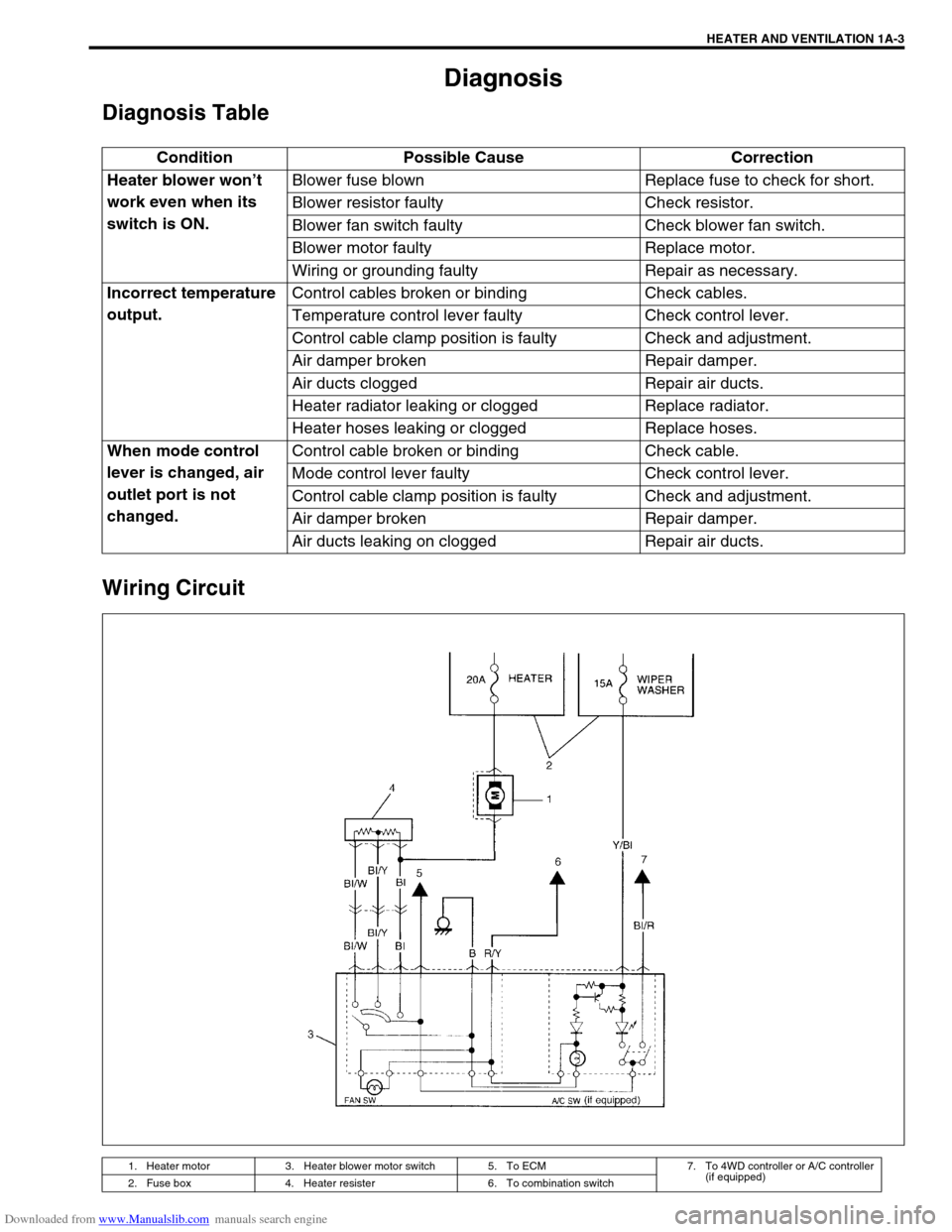
Wiring Circuit
Condition Possible Cause Correction
Heater blower won’t
work even when its
switch is ON.Blower fuse blown Replace fuse to check for short.
Blower resistor faulty Check resistor.
Blower fan switch faulty Check blower fan switch.
Blower motor faulty Replace motor.
Wiring or grounding faulty Repair as necessary.
Incorrect temperature
output.Control cables broken or binding Check cables.
Temperature control lever faulty Check control lever.
Control cable clamp position is faulty Check and adjustment.
Air damper broken Repair damper.
Air ducts clogged Repair air ducts.
Heater radiator leaking or clogged Replace radiator.
Heater hoses leaking or clogged Replace hoses.
When mode control
lever is changed, air
outlet port is not
changed.Control cable broken or binding Check cable.
Mode control lever faulty Check control lever.
Control cable clamp position is faulty Check and adjustment.
Air damper broken Repair damper.
Air ducts leaking on clogged Repair air ducts.
1. Heater motor 3. Heater blower motor switch 5. To ECM 7. To 4WD controller or A/C controller
(if equipped)
2. Fuse box 4. Heater resister 6. To combination switch
Page 66 of 687

Downloaded from www.Manualslib.com manuals search engine AIR CONDITIONING (OPTIONAL) 1B-5
Diagnosis
General Diagnosis Table
Condition Possible Cause Correction
Cool air won’t come
out (A/C system won’t
operative)No refrigerant Perform recover, evacuation and charging.
Fuse blown Check fuses in main and circuit fuse
boxes, and check short circuit to ground.
A/C switch faulty Check A/C switch.
Blower fan switch faulty Check blower fan switch referring to Sec-
tion 1A.
A/C evaporator thermistor faulty Check A/C evaporator thermistor.
Dual pressure switch faulty Check dual pressure switch.
Wiring or grounding faulty Repair as necessary.
ECT sensor faulty Check ECT sensor referring to Section 6E.
ECM and its circuit faulty Check ECM and its circuit referring to Sec-
tion 6E.
4WD controller faulty Check 4WD controller referring to Section
3D.
Cool air won’t come
out (A/C compressor
won't operative)ECM faulty Check ECM and its circuit referring to Sec-
tion 6E.
Magnet clutch faulty Check magnet clutch.
Compressor drive belt loosen or broken Adjust or replace drive belt.
Compressor faulty Check compressor.
Cool air won’t come
out (A/C condenser
cooling fan motor
won’t operative)Fuse blown Check “A/C” fuse in main fuse box, and
check short circuit to ground.
Wiring or grounding faulty Repair as necessary.
Condenser cooling fan motor relay
faultyCheck condenser cooling fan motor relay.
Condenser cooling fan motor faulty Check condenser cooling fan motor.
Cool air won’t come
out (Blower fan motor
won’t operative)Fuse blown Check fuses in main and circuit fuse
boxes, and check short circuit to ground.
Blower fan motor resistor faulty Check blower fan motor resistor referring
to Section 1A.
Blower fan switch faulty Check blower fan switch referring to Sec-
tion 1A.
Wiring or grounding faulty Repair as necessary.
Blower fan motor faulty Check blower fan motor referring to Sec-
tion 1A.
Page 77 of 687
![SUZUKI JIMNY 2005 3.G Service Workshop Manual Downloaded from www.Manualslib.com manuals search engine 1B-16 AIR CONDITIONING (OPTIONAL)
Electronical Diagnosis
Wiring Diagram
[A]: 4WD model 4. Dual pressure switch 9. Thermal switch 14. Circuit fu SUZUKI JIMNY 2005 3.G Service Workshop Manual Downloaded from www.Manualslib.com manuals search engine 1B-16 AIR CONDITIONING (OPTIONAL)
Electronical Diagnosis
Wiring Diagram
[A]: 4WD model 4. Dual pressure switch 9. Thermal switch 14. Circuit fu](/img/20/7588/w960_7588-76.png)
Downloaded from www.Manualslib.com manuals search engine 1B-16 AIR CONDITIONING (OPTIONAL)
Electronical Diagnosis
Wiring Diagram
[A]: 4WD model 4. Dual pressure switch 9. Thermal switch 14. Circuit fuse box
[B]: 2WD model 5. 4WD controller 10. Ignition switch 15. Main fuse box
1. Blower fan motor 6. Condenser cooling fan motor relay 11. A/C evaporator thermistor 16. Generator
2. Blower fan motor resistor 7. Condenser cooling fan motor 12. ECT sensor 17. ECM
3. Blower fan motor switch and A/C switch 8. Compressor 13. Lighting switch
Page 79 of 687
![SUZUKI JIMNY 2005 3.G Service Workshop Manual Downloaded from www.Manualslib.com manuals search engine 1B-18 AIR CONDITIONING (OPTIONAL)
Terminal arrangement of ECM coupler (Viewed from harness side)
1. Blower fan motor 8. Compressor [A]: To “A SUZUKI JIMNY 2005 3.G Service Workshop Manual Downloaded from www.Manualslib.com manuals search engine 1B-18 AIR CONDITIONING (OPTIONAL)
Terminal arrangement of ECM coupler (Viewed from harness side)
1. Blower fan motor 8. Compressor [A]: To “A](/img/20/7588/w960_7588-78.png)
Downloaded from www.Manualslib.com manuals search engine 1B-18 AIR CONDITIONING (OPTIONAL)
Terminal arrangement of ECM coupler (Viewed from harness side)
1. Blower fan motor 8. Compressor [A]: To “A/C” fuse (25A) in main fuse box
2. Dual pressure switch 9. Thermal switch [B]: To “HEATER” fuse (20A) in circuit fuse box
3. A/C switch 10. Main relay [C]: To “FI” fuse (15A) in main fuse box
4. A/C evaporator thermistor 11. Engine earth [D]: 4WD model
5. ECT sensor 12. Blower fan motor switch [E]: 2WD model
6. Condenser cooling fan motor relay 13. 4WD controller
7. Condenser cooling fan motor 14. ECM
Page 177 of 687
Downloaded from www.Manualslib.com manuals search engine 3D-4 FRONT SUSPENSION
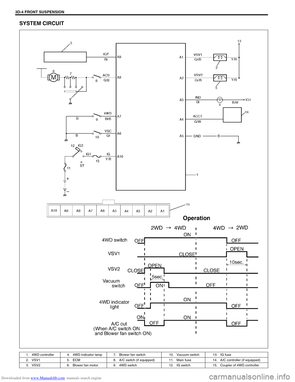
SYSTEM CIRCUIT
1. 4WD controller 4. 4WD indicator lamp 7. Blower fan switch 10. Vacuum switch 13. IG fuse
2. VSV1 5. ECM 8. A/C switch (if equipped) 11. Main fuse 14. A/C controller (if equipped)
3. VSV2 6. Blower fan motor 9. 4WD switch 12. IG switch 15. Coupler of 4WD controller
Page 329 of 687
Downloaded from www.Manualslib.com manuals search engine 5E-12 ANTILOCK BRAKE SYSTEM (ABS)
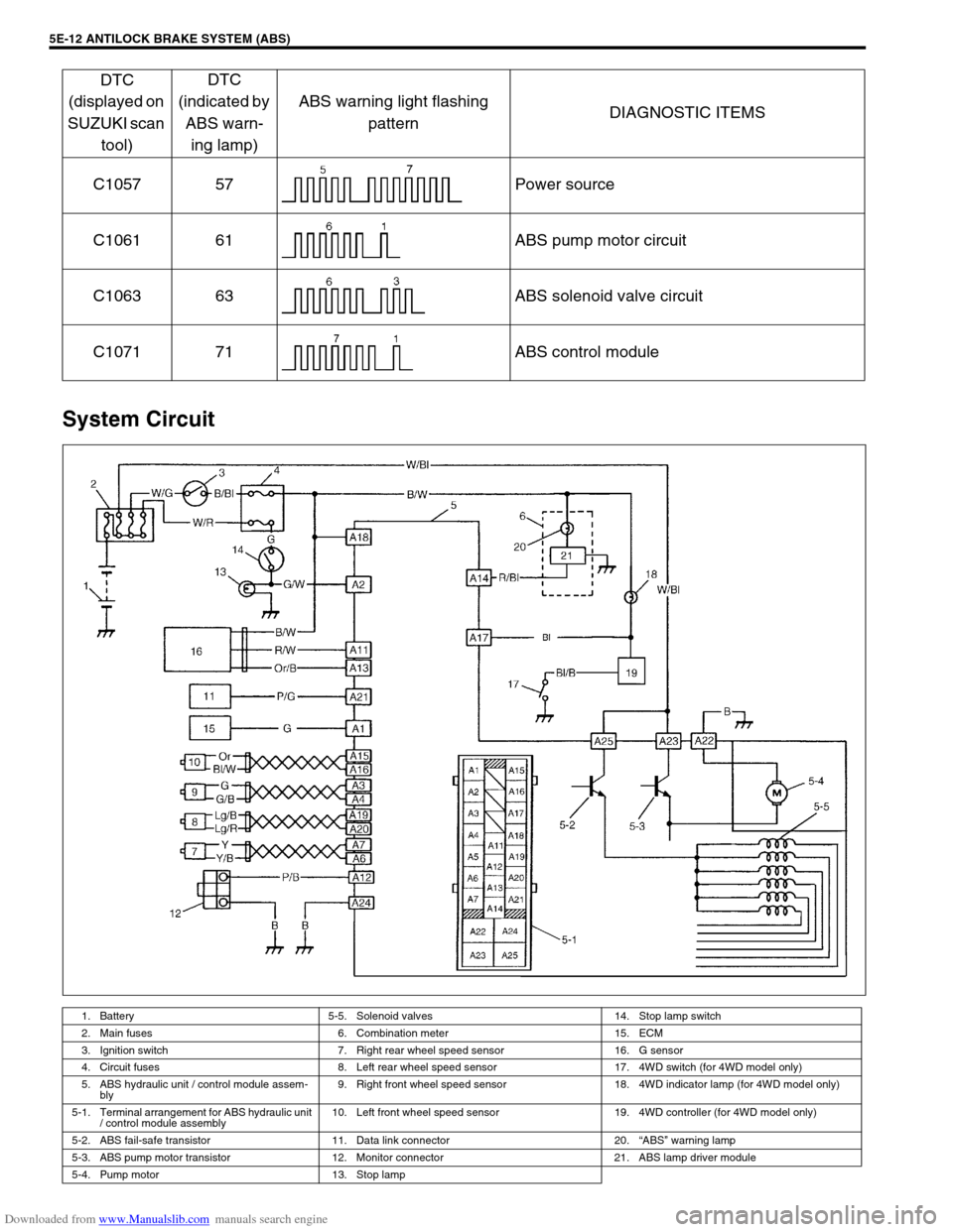
System Circuit
C1057 57 Power source
C1061 61 ABS pump motor circuit
C1063 63 ABS solenoid valve circuit
C1071 71 ABS control module
1. Battery 5-5. Solenoid valves 14. Stop lamp switch
2. Main fuses 6. Combination meter 15. ECM
3. Ignition switch 7. Right rear wheel speed sensor 16. G sensor
4. Circuit fuses 8. Left rear wheel speed sensor 17. 4WD switch (for 4WD model only)
5. ABS hydraulic unit / control module assem-
bly9. Right front wheel speed sensor 18. 4WD indicator lamp (for 4WD model only)
5-1. Terminal arrangement for ABS hydraulic unit
/ control module assembly10. Left front wheel speed sensor 19. 4WD controller (for 4WD model only)
5-2. ABS fail-safe transistor 11. Data link connector 20.“ABS” warning lamp
5-3. ABS pump motor transistor 12. Monitor connector 21. ABS lamp driver module
5-4. Pump motor 13. Stop lamp
DTC
(displayed on
SUZUKI scan
tool)DTC
(indicated by
ABS warn-
ing lamp)ABS warning light flashing
patternDIAGNOSTIC ITEMS
Page 331 of 687
Downloaded from www.Manualslib.com manuals search engine 5E-14 ANTILOCK BRAKE SYSTEM (ABS)
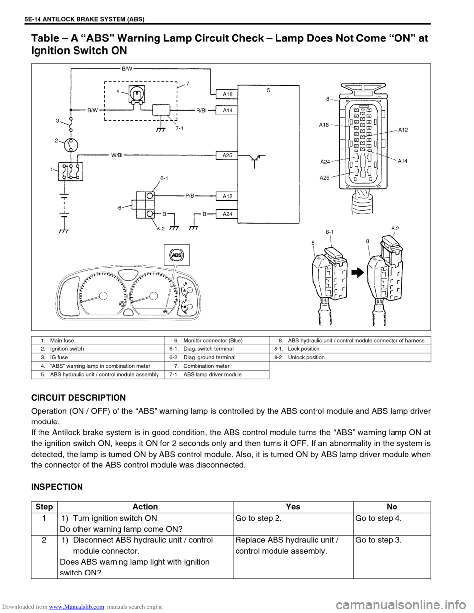
Table – A “ABS” Warning Lamp Circuit Check – Lamp Does Not Come “ON” at
Ignition Switch ON
CIRCUIT DESCRIPTION
Operation (ON / OFF) of the “ABS” warning lamp is controlled by the ABS control module and ABS lamp driver
module.
If the Antilock brake system is in good condition, the ABS control module turns the “ABS” warning lamp ON at
the ignition switch ON, keeps it ON for 2 seconds only and then turns it OFF. If an abnormality in the system is
detected, the lamp is turned ON by ABS control module. Also, it is turned ON by ABS lamp driver module when
the connector of the ABS control module was disconnected.
INSPECTION
1. Main fuse 6. Monitor connector (Blue) 8. ABS hydraulic unit / control module connector of harness
2. Ignition switch 6-1. Diag. switch terminal 8-1. Lock position
3. IG fuse 6-2. Diag. ground terminal 8-2. Unlock position
4.“ABS” warning lamp in combination meter 7. Combination meter
5. ABS hydraulic unit / control module assembly 7-1. ABS lamp driver module
Step Action Yes No
1 1) Turn ignition switch ON.
Do other warning lamp come ON?Go to step 2. Go to step 4.
2 1) Disconnect ABS hydraulic unit / control
module connector.
Does ABS warning lamp light with ignition
switch ON?Replace ABS hydraulic unit /
control module assembly.Go to step 3.
Page 332 of 687

Downloaded from www.Manualslib.com manuals search engine ANTILOCK BRAKE SYSTEM (ABS) 5E-15
Table – B “ABS” Warning Lamp Circuit Check – Lamp Comes “ON” Steady
Refer to TABLE – A for System Circuit Diagram and Circuit Description.
INSPECTION
3 1) Remove combination meter.
Is bulb of ABS warning lamp in good condition?“R/Bl” circuit shorted to ground.
If OK, replace ABS warning cir-
cuit (lamp driver module).Replace bulb.
4 Is IG fuse in good condition? Open in “B/W” wire to combina-
tion meter or poor connection.Repair and replace. Step Action Yes No
Step Action Yes No
1 Perform diagnostic trouble code check. Is there
any DTC (including code No.12, NO CODES on
SUZUKI scan tool) exists?Go to step 2. Go to step 3.
2 Is malfunction DTC (other than code No.12)
exists at step 1?Go to step 7 of ABS diag-
nostic flow table in this
section.Go to step 3.
3 1) Disconnect ABS hydraulic unit / control
module connector.
2) Check for proper connection to ABS hydrau-
lic unit / control module connector at termi-
nals “A14” and “A18”.
3) If OK, turn ignition switch “ON” and mea-
sure voltage at terminal “A18” of connector.
Is it 10 – 14 V?Go to step 4.“B/W” circuit open.
4 1) With ABS control module connector discon-
nected, turn ignition switch ON and light
ABS warning lamp.
2) Connect terminal “A14” of disconnected
connector to ground using service wire.
Does “ABS warning lamp” turn off?Go to step 5.“R/Bl” circuit open.
If wire and connection are
OK, replace ABS lamp
driver module.
5 1) Measure resistance from connector termi-
nal “A24” to body ground.
Is continuity indicated?Substitute a known-good
ABS hydraulic unit / con-
trol module assembly and
recheck.“B” circuit open.