Lines SUZUKI JIMNY 2005 3.G Service User Guide
[x] Cancel search | Manufacturer: SUZUKI, Model Year: 2005, Model line: JIMNY, Model: SUZUKI JIMNY 2005 3.GPages: 687, PDF Size: 13.38 MB
Page 260 of 687
Downloaded from www.Manualslib.com manuals search engine PROPELLER SHAFTS 4B-7
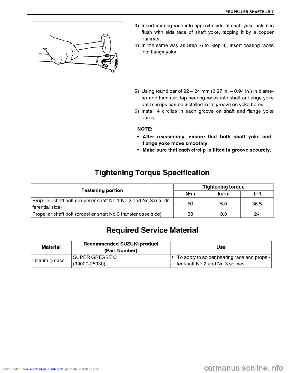
3) Insert bearing race into opposite side of shaft yoke until it is
flush with side face of shaft yoke, tapping it by a copper
hammer.
4) In the same way as Step 2) to Step 3), insert bearing races
into flange yoke.
5) Using round bar of 22 – 24 mm (0.87 in. – 0.94 in.) in diame-
ter and hammer, tap bearing races into shaft or flange yoke
until circlips can be installed in its groove on yoke bores.
6) Install 4 circlips in each groove on shaft and flange yoke
bores.
Tightening Torque Specification
Required Service Material
NOTE:
After reassembly, ensure that both shaft yoke and
flange yoke move smoothly.
Make sure that each circlip is fitted in groove securely.
Fastening portionTightening torque
Nm kg-m lb-ft
Propeller shaft bolt (propeller shaft No.1 No.2 and No.3 rear dif-
ferential side)50 5.0 36.5
Propeller shaft bolt (propeller shaft No.3 transfer case side) 33 3.3 24
MaterialRecommended SUZUKI product
(Part Number)Use
Lithium greaseSUPER GREASE C
(99000-25030)To apply to spider bearing race and propel-
ler shaft No.2 and No.3 splines.
Page 266 of 687

Downloaded from www.Manualslib.com manuals search engine BRAKES 5-5
Diagnosis Table
Condition Possible Cause Correction
Not enough braking
forceBrake oil leakage from brake lines Locate leaking point and repair.
Brake disc or pads stained with oil Clean or replace.
Overheated brakes Determine cause and repair.
Poor contact of shoes on brake drum Repair for proper contact.
Brake shoes linings stained with oil or wet with
waterReplace.
Badly worn brake shoe linings Replace.
Defective wheel cylinders Repair or replace.
Malfunctioning caliper assembly Repair or replace.
Air in system Bleed system.
Maladjusted sensor spring length of LSPV Check or adjust.
Broken sensor spring of LSPV Replace.
Defective collar of LSPV Replace.
Malfunctioning ABS (Antilock brake system), if
equippedCheck system and replace as nec-
essary.
Brake pull (Brakes not
working in unison)Pad or shoe linings are wet with water or
stained with oil in some brakesReplace.
Drum-to-shoe clearance out of adjustment in
some brakes (Malfunctioning auto adjusting
mechanism)Check for inoperative auto adjusting
mechanism.
Drum is out of round in some brakes Replace.
Wheel tires are inflated unequally Inflate equally.
Malfunctioning wheel cylinders Repair or replace.
Disturbed front wheel alignment Adjust as prescribed.
Unmatched tires on same axle Tires with approximately the same
amount of tread should be used on
the same axle.
Restricted brake tubes or hoses Check for soft hoses and damaged
lines.
Replace with new hoses and new
double-walled steel brake tubing.
Malfunctioning caliper assembly Check for stuck or sluggish pistons
and proper lubrication of caliper
slide bush.
Loose suspension parts Caliper should slide.
Check all suspension mountings.
Loose calipers Check and torque bolts to specifica-
tions.
Noise (high pitched
squeak without brake
applied)Front lining worn out Replace brake pads.
Rear brake locked pre-
maturelyMaladjusted sensor spring length of LSPV Check or adjust.
Malfunctioning LSPV assembly Replace assembly.
Brake locked
(For vehicles
equipped with ABS)Malfunctioning ABS, if equipped Check system and replace as nec-
essary.
Page 270 of 687
Downloaded from www.Manualslib.com manuals search engine BRAKES 5-9
Excessive Pedal Travel Check
1) Start engine.
2) Depress brake pedal a few times.
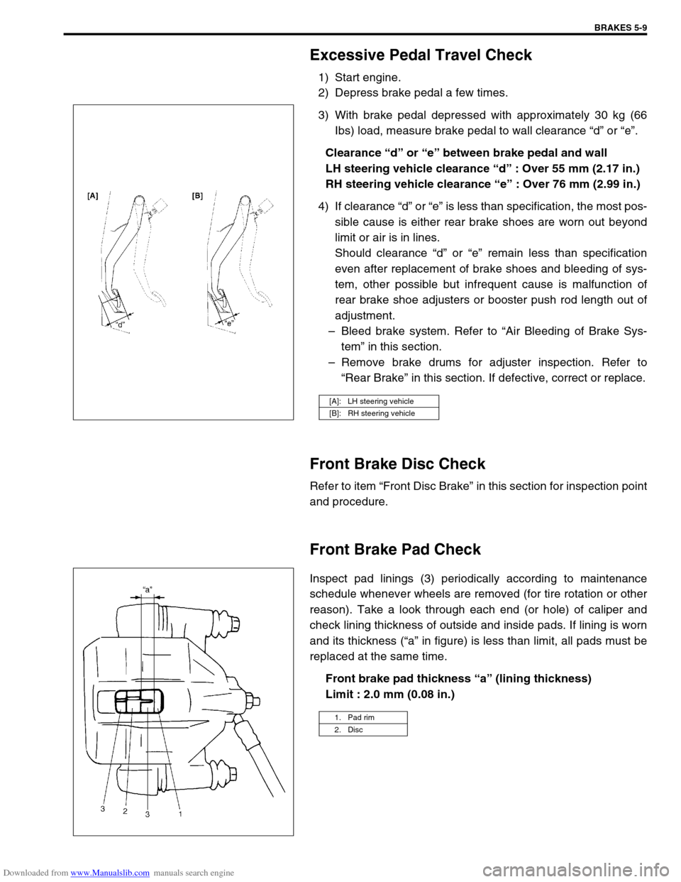
3) With brake pedal depressed with approximately 30 kg (66
Ibs) load, measure brake pedal to wall clearance “d” or “e”.
Clearance “d” or “e” between brake pedal and wall
LH steering vehicle clearance “d” : Over 55 mm (2.17 in.)
RH steering vehicle clearance “e” : Over 76 mm (2.99 in.)
4) If clearance “d” or “e” is less than specification, the most pos-
sible cause is either rear brake shoes are worn out beyond
limit or air is in lines.
Should clearance “d” or “e” remain less than specification
even after replacement of brake shoes and bleeding of sys-
tem, other possible but infrequent cause is malfunction of
rear brake shoe adjusters or booster push rod length out of
adjustment.
–Bleed brake system. Refer to “Air Bleeding of Brake Sys-
tem” in this section.
–Remove brake drums for adjuster inspection. Refer to
“Rear Brake” in this section. If defective, correct or replace.
Front Brake Disc Check
Refer to item “Front Disc Brake” in this section for inspection point
and procedure.
Front Brake Pad Check
Inspect pad linings (3) periodically according to maintenance
schedule whenever wheels are removed (for tire rotation or other
reason). Take a look through each end (or hole) of caliper and
check lining thickness of outside and inside pads. If lining is worn
and its thickness (“a” in figure) is less than limit, all pads must be
replaced at the same time.
Front brake pad thickness “a” (lining thickness)
Limit : 2.0 mm (0.08 in.)
[A]: LH steering vehicle
[B]: RH steering vehicle
1. Pad rim
2. Disc
Page 272 of 687
Downloaded from www.Manualslib.com manuals search engine BRAKES 5-11
Rear Drum Brake Shoe Adjustment
Rear brake has self-adjusting mechanism but it does require
adjustment for proper drum to shoe clearance when brake shoe
has been replaced or brake drum has been removed for some
other service.
Adjustment is automatically accomplished by depressing brake
pedal about 30 times with approximately 30 kg (66 Ibs) load after
all parts are installed.
Then check brake drum for dragging and brake system for proper
performance. After lowering vehicle from hoist, brake test should
be performed.
Parking Brake Inspection and Adjustment
INSPECTION
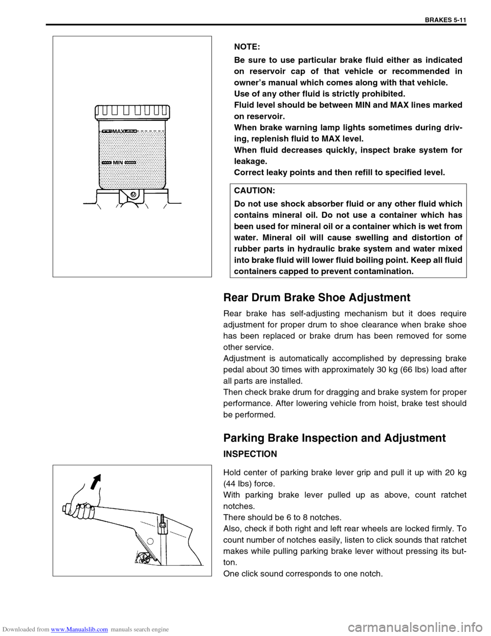
Hold center of parking brake lever grip and pull it up with 20 kg
(44 Ibs) force.
With parking brake lever pulled up as above, count ratchet
notches.
There should be 6 to 8 notches.
Also, check if both right and left rear wheels are locked firmly. To
count number of notches easily, listen to click sounds that ratchet
makes while pulling parking brake lever without pressing its but-
ton.
One click sound corresponds to one notch.NOTE:
Be sure to use particular brake fluid either as indicated
on reservoir cap of that vehicle or recommended in
owner’s manual which comes along with that vehicle.
Use of any other fluid is strictly prohibited.
Fluid level should be between MIN and MAX lines marked
on reservoir.
When brake warning lamp lights sometimes during driv-
ing, replenish fluid to MAX level.
When fluid decreases quickly, inspect brake system for
leakage.
Correct leaky points and then refill to specified level.
CAUTION:
Do not use shock absorber fluid or any other fluid which
contains mineral oil. Do not use a container which has
been used for mineral oil or a container which is wet from
water. Mineral oil will cause swelling and distortion of
rubber parts in hydraulic brake system and water mixed
into brake fluid will lower fluid boiling point. Keep all fluid
containers capped to prevent contamination.
Page 274 of 687
Downloaded from www.Manualslib.com manuals search engine BRAKES 5-13
CHECK AIR TIGHTNESS
1) Start engine.
2) Stop engine after running for 1 to 2 minutes.
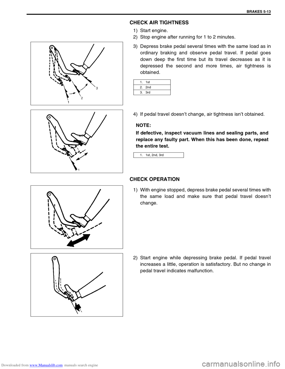
3) Depress brake pedal several times with the same load as in
ordinary braking and observe pedal travel. If pedal goes
down deep the first time but its travel decreases as it is
depressed the second and more times, air tightness is
obtained.
4) If pedal travel doesn’t change, air tightness isn’t obtained.
CHECK OPERATION
1) With engine stopped, depress brake pedal several times with
the same load and make sure that pedal travel doesn’t
change.
2) Start engine while depressing brake pedal. If pedal travel
increases a little, operation is satisfactory. But no change in
pedal travel indicates malfunction.
1. 1st
2. 2nd
3. 3rd
NOTE:
If defective, inspect vacuum lines and sealing parts, and
replace any faulty part. When this has been done, repeat
the entire test.
1. 1st, 2nd, 3rd
Page 278 of 687
Downloaded from www.Manualslib.com manuals search engine BRAKES 5-17
On-Vehicle Service
Air Bleeding of Brake System
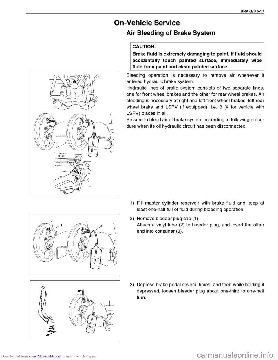
Bleeding operation is necessary to remove air whenever it
entered hydraulic brake system.
Hydraulic lines of brake system consists of two separate lines,
one for front wheel brakes and the other for rear wheel brakes. Air
bleeding is necessary at right and left front wheel brakes, left rear
wheel brake and LSPV (if equipped), i.e. 3 (4 for vehicle with
LSPV) places in all.
Be sure to bleed air of brake system according to following proce-
dure when its oil hydraulic circuit has been disconnected.
1) Fill master cylinder reservoir with brake fluid and keep at
least one-half full of fluid during bleeding operation.
2) Remove bleeder plug cap (1).
Attach a vinyl tube (2) to bleeder plug, and insert the other
end into container (3).
3) Depress brake pedal several times, and then while holding it
depressed, loosen bleeder plug about one-third to one-half
turn. CAUTION:
Brake fluid is extremely damaging to paint. If fluid should
accidentally touch painted surface, immediately wipe
fluid from paint and clean painted surface.
Page 285 of 687
Downloaded from www.Manualslib.com manuals search engine 5-24 BRAKES
ASSEMBLY
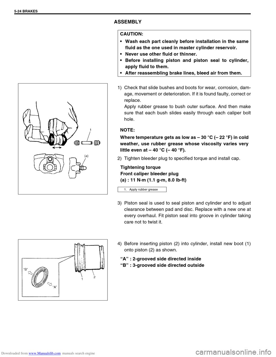
1) Check that slide bushes and boots for wear, corrosion, dam-
age, movement or deterioration. If it is found faulty, correct or
replace.
Apply rubber grease to bush outer surface. And then make
sure that each bush slides easily through each caliper bolt
hole.
2) Tighten bleeder plug to specified torque and install cap.
Tightening torque
Front caliper bleeder plug
(a) : 11 N·m (1.1 g-m, 8.0 lb-ft)
3) Piston seal is used to seal piston and cylinder and to adjust
clearance between pad and disc. Replace with a new one at
every overhaul. Fit piston seal into groove in cylinder taking
care not to twist it.
4) Before inserting piston (2) into cylinder, install new boot (1)
onto piston (2) as shown.
“A” : 2-grooved side directed inside
“B” : 3-grooved side directed outside CAUTION:
Wash each part cleanly before installation in the same
fluid as the one used in master cylinder reservoir.
Never use other fluid or thinner.
Before installing piston and piston seal to cylinder,
apply fluid to them.
After reassembling brake lines, bleed air from them.
NOTE:
Where temperature gets as low as – 30 °C (– 22 °F) in cold
weather, use rubber grease whose viscosity varies very
little even at – 40 °C (– 40 °F).
1. Apply rubber grease
Page 291 of 687
Downloaded from www.Manualslib.com manuals search engine 5-30 BRAKES
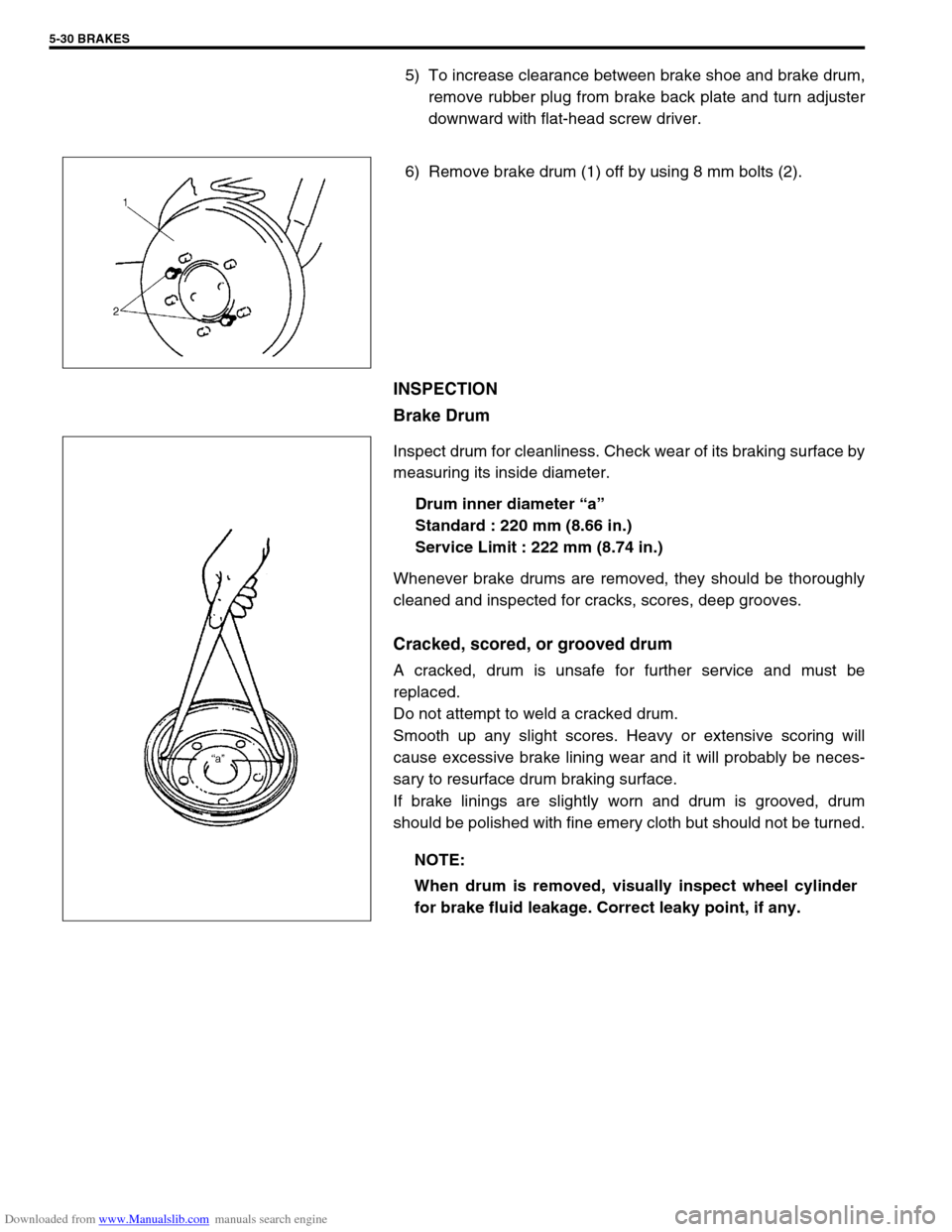
5) To increase clearance between brake shoe and brake drum,
remove rubber plug from brake back plate and turn adjuster
downward with flat-head screw driver.
6) Remove brake drum (1) off by using 8 mm bolts (2).
INSPECTION
Brake Drum
Inspect drum for cleanliness. Check wear of its braking surface by
measuring its inside diameter.
Drum inner diameter “a”
Standard : 220 mm (8.66 in.)
Service Limit : 222 mm (8.74 in.)
Whenever brake drums are removed, they should be thoroughly
cleaned and inspected for cracks, scores, deep grooves.
Cracked, scored, or grooved drum
A cracked, drum is unsafe for further service and must be
replaced.
Do not attempt to weld a cracked drum.
Smooth up any slight scores. Heavy or extensive scoring will
cause excessive brake lining wear and it will probably be neces-
sary to resurface drum braking surface.
If brake linings are slightly worn and drum is grooved, drum
should be polished with fine emery cloth but should not be turned.
NOTE:
When drum is removed, visually inspect wheel cylinder
for brake fluid leakage. Correct leaky point, if any.
Page 299 of 687
Downloaded from www.Manualslib.com manuals search engine 5-38 BRAKES
INSTALLATION
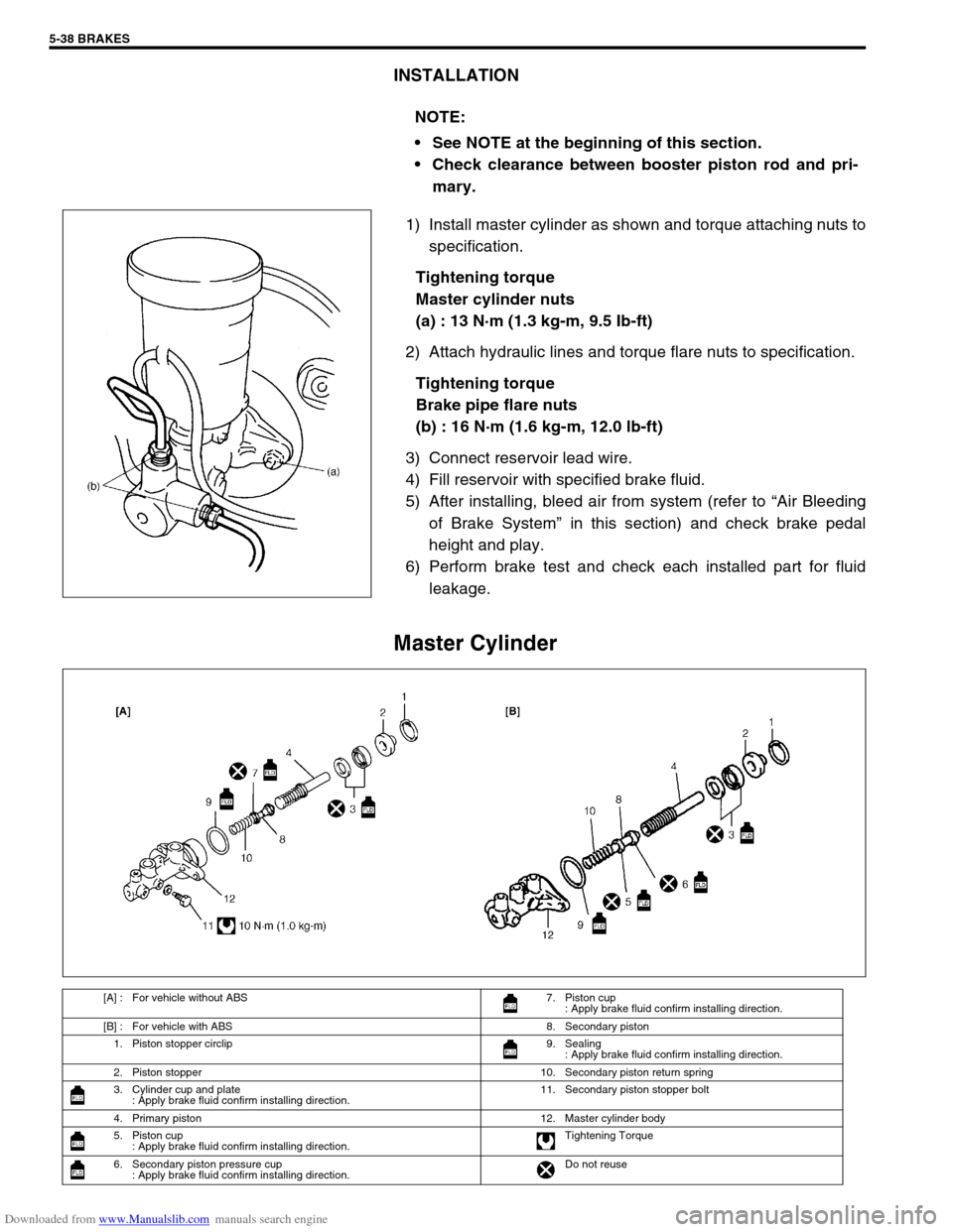
1) Install master cylinder as shown and torque attaching nuts to
specification.
Tightening torque
Master cylinder nuts
(a) : 13 N·m (1.3 kg-m, 9.5 Ib-ft)
2) Attach hydraulic lines and torque flare nuts to specification.
Tightening torque
Brake pipe flare nuts
(b) : 16 N·m (1.6 kg-m, 12.0 lb-ft)
3) Connect reservoir lead wire.
4) Fill reservoir with specified brake fluid.
5) After installing, bleed air from system (refer to “Air Bleeding
of Brake System” in this section) and check brake pedal
height and play.
6) Perform brake test and check each installed part for fluid
leakage.
Master Cylinder
NOTE:
See NOTE at the beginning of this section.
Check clearance between booster piston rod and pri-
mary.
[A] : For vehicle without ABS 7. Piston cup
: Apply brake fluid confirm installing direction.
[B] : For vehicle with ABS 8. Secondary piston
1. Piston stopper circlip 9. Sealing
: Apply brake fluid confirm installing direction.
2. Piston stopper 10. Secondary piston return spring
3. Cylinder cup and plate
: Apply brake fluid confirm installing direction.11. Secondary piston stopper bolt
4. Primary piston 12. Master cylinder body
5. Piston cup
: Apply brake fluid confirm installing direction.Tightening Torque
6. Secondary piston pressure cup
: Apply brake fluid confirm installing direction.Do not reuse
Page 358 of 687
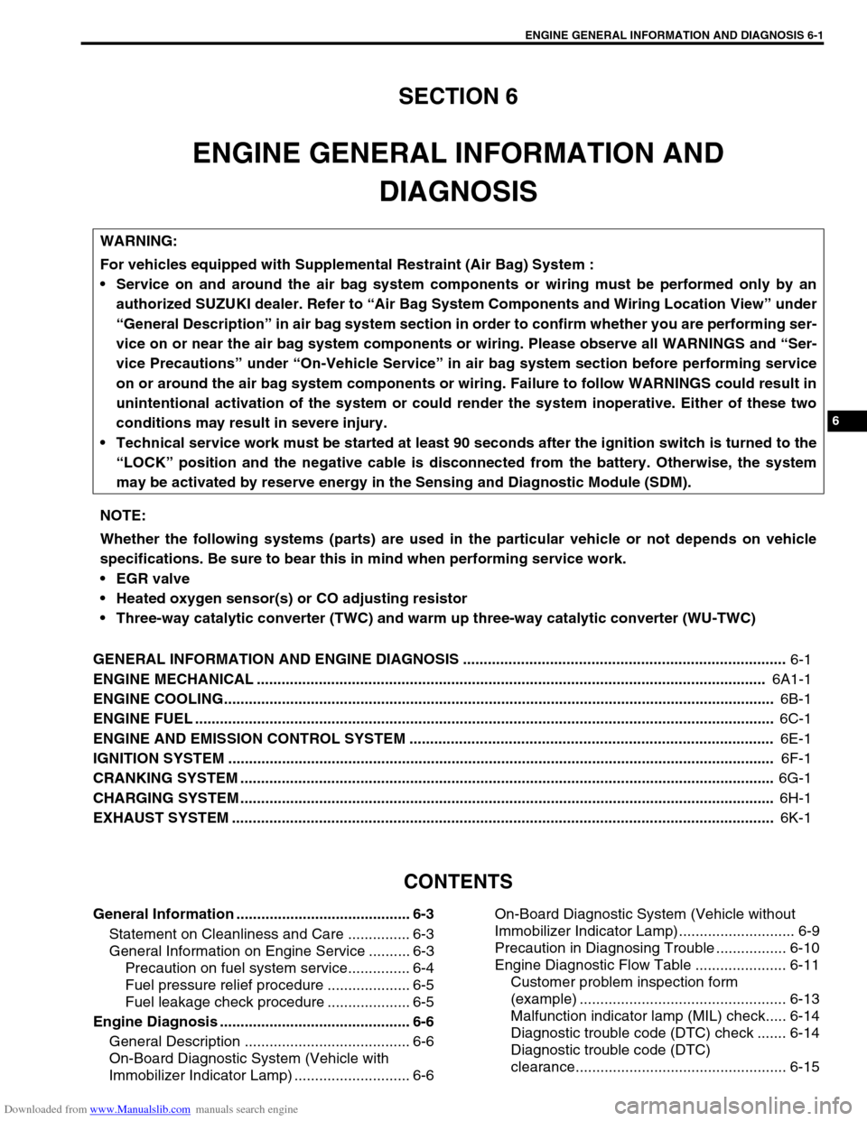
Downloaded from www.Manualslib.com manuals search engine ENGINE GENERAL INFORMATION AND DIAGNOSIS 6-1
6F2
6G
6H
6K
7A
7A1
7B1
7C1
7D
7E
7F
8B
6
8D
8E
8B
9
10A
10B
SECTION 6
ENGINE GENERAL INFORMATION AND
DIAGNOSIS
GENERAL INFORMATION AND ENGINE DIAGNOSIS ..............................................................................
6-1
ENGINE MECHANICAL ...........................................................................................................................
6A1-1
ENGINE COOLING.....................................................................................................................................
6B-1
ENGINE FUEL ............................................................................................................................................
6C-1
ENGINE AND EMISSION CONTROL SYSTEM ........................................................................................
6E-1
IGNITION SYSTEM ....................................................................................................................................
6F-1
CRANKING SYSTEM .................................................................................................................................
6G-1
CHARGING SYSTEM .................................................................................................................................
6H-1
EXHAUST SYSTEM ...................................................................................................................................
6K-1
CONTENTS
General Information .......................................... 6-3
Statement on Cleanliness and Care ............... 6-3
General Information on Engine Service .......... 6-3
Precaution on fuel system service............... 6-4
Fuel pressure relief procedure .................... 6-5
Fuel leakage check procedure .................... 6-5
Engine Diagnosis .............................................. 6-6
General Description ........................................ 6-6
On-Board Diagnostic System (Vehicle with
Immobilizer Indicator Lamp) ............................ 6-6On-Board Diagnostic System (Vehicle without
Immobilizer Indicator Lamp)............................ 6-9
Precaution in Diagnosing Trouble ................. 6-10
Engine Diagnostic Flow Table ...................... 6-11
Customer problem inspection form
(example) .................................................. 6-13
Malfunction indicator lamp (MIL) check..... 6-14
Diagnostic trouble code (DTC) check ....... 6-14
Diagnostic trouble code (DTC)
clearance................................................... 6-15 WARNING:
For vehicles equipped with Supplemental Restraint (Air Bag) System :
Service on and around the air bag system components or wiring must be performed only by an
authorized SUZUKI dealer. Refer to “Air Bag System Components and Wiring Location View” under
“General Description” in air bag system section in order to confirm whether you are performing ser-
vice on or near the air bag system components or wiring. Please observe all WARNINGS and “Ser-
vice Precautions” under “On-Vehicle Service” in air bag system section before performing service
on or around the air bag system components or wiring. Failure to follow WARNINGS could result in
unintentional activation of the system or could render the system inoperative. Either of these two
conditions may result in severe injury.
Technical service work must be started at least 90 seconds after the ignition switch is turned to the
“LOCK” position and the negative cable is disconnected from the battery. Otherwise, the system
may be activated by reserve energy in the Sensing and Diagnostic Module (SDM).
NOTE:
Whether the following systems (parts) are used in the particular vehicle or not depends on vehicle
specifications. Be sure to bear this in mind when performing service work.
EGR valve
Heated oxygen sensor(s) or CO adjusting resistor
Three-way catalytic converter (TWC) and warm up three-way catalytic converter (WU-TWC)