coolant SUZUKI JIMNY 2005 3.G Service User Guide
[x] Cancel search | Manufacturer: SUZUKI, Model Year: 2005, Model line: JIMNY, Model: SUZUKI JIMNY 2005 3.GPages: 687, PDF Size: 13.38 MB
Page 96 of 687

Downloaded from www.Manualslib.com manuals search engine AIR CONDITIONING (OPTIONAL) 1B-35
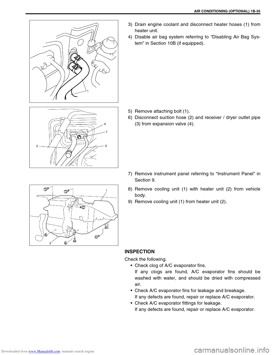
3) Drain engine coolant and disconnect heater hoses (1) from
heater unit.
4) Disable air bag system referring to “Disabling Air Bag Sys-
tem” in Section 10B (if equipped).
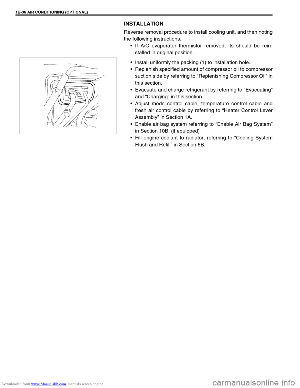
5) Remove attaching bolt (1).
6) Disconnect suction hose (2) and receiver / dryer outlet pipe
(3) from expansion valve (4).
7) Remove instrument panel referring to “Instrument Panel” in
Section 9.
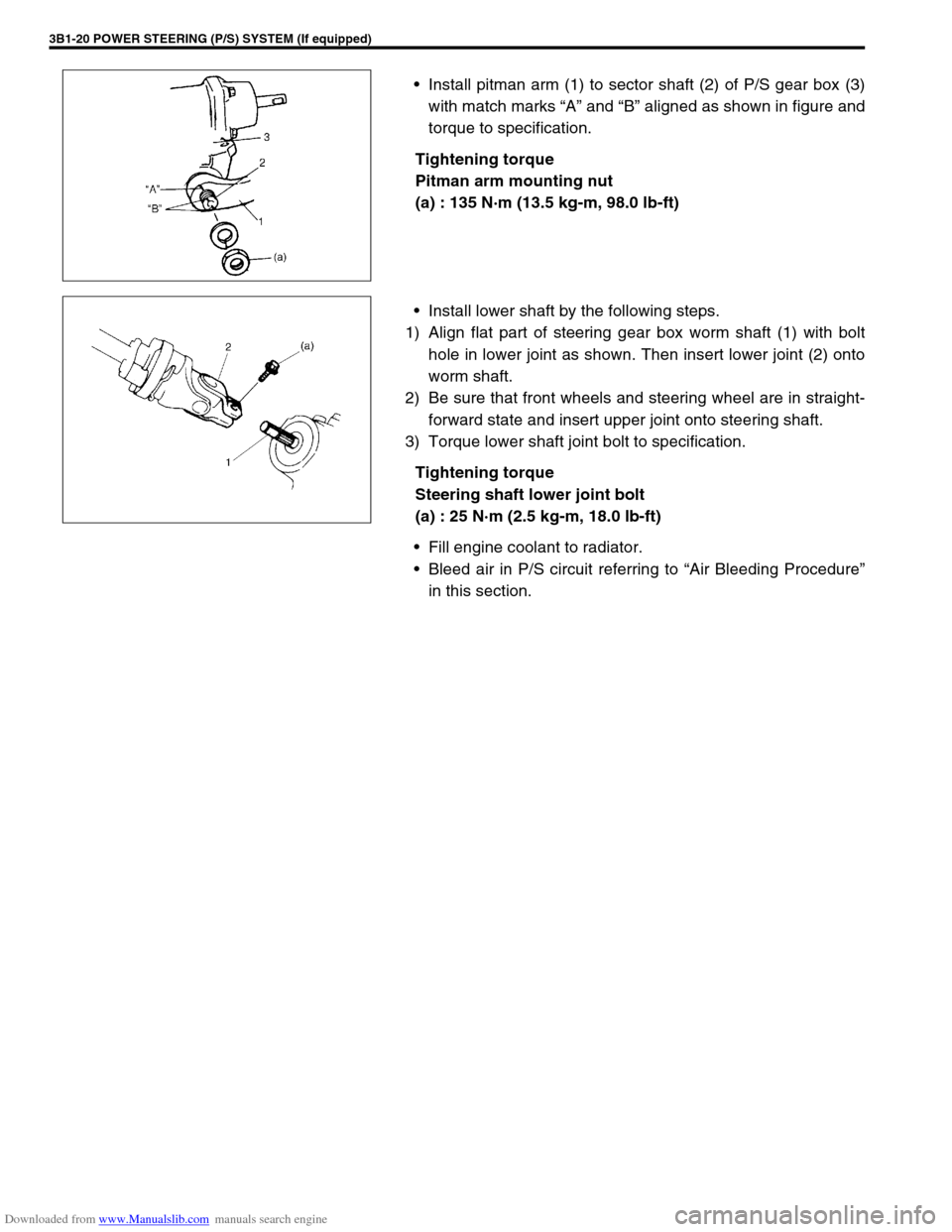
8) Remove cooling unit (1) with heater unit (2) from vehicle
body.
9) Remove cooling unit (1) from heater unit (2).
INSPECTION
Check the following.
Check clog of A/C evaporator fins.
If any clogs are found, A/C evaporator fins should be
washed with water, and should be dried with compressed
air.
Check A/C evaporator fins for leakage and breakage.
If any defects are found, repair or replace A/C evaporator.
Check A/C evaporator fittings for leakage.
If any defects are found, repair or replace A/C evaporator.
Page 97 of 687

Downloaded from www.Manualslib.com manuals search engine 1B-36 AIR CONDITIONING (OPTIONAL)
INSTALLATION
Reverse removal procedure to install cooling unit, and then noting
the following instructions.
If A/C evaporator thermistor removed, its should be rein-
stalled in original position.
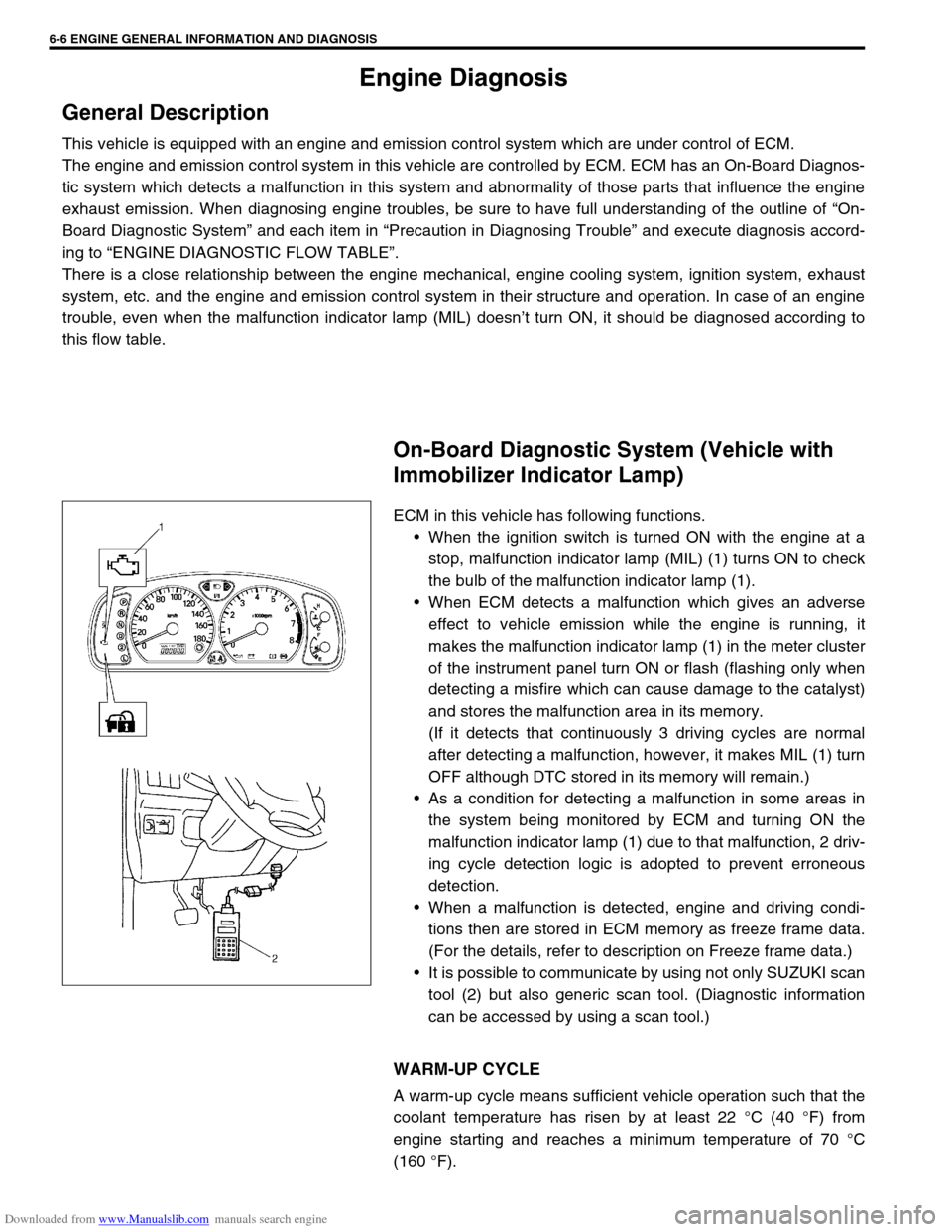
Install uniformly the packing (1) to installation hole.
Replenish specified amount of compressor oil to compressor
suction side by referring to “Replenishing Compressor Oil” in
this section.
Evacuate and charge refrigerant by referring to “Evacuating”
and “Charging” in this section.
Adjust mode control cable, temperature control cable and
fresh air control cable by referring to “Heater Control Lever
Assembly” in Section 1A.
Enable air bag system referring to “Enable Air Bag System”
in Section 10B. (if equipped)
Fill engine coolant to radiator, referring to “Cooling System
Flush and Refill” in Section 6B.
Page 151 of 687

Downloaded from www.Manualslib.com manuals search engine 3B1-20 POWER STEERING (P/S) SYSTEM (If equipped)
Install pitman arm (1) to sector shaft (2) of P/S gear box (3)
with match marks “A” and “B” aligned as shown in figure and
torque to specification.
Tightening torque
Pitman arm mounting nut
(a) : 135 N·m (13.5 kg-m, 98.0 lb-ft)
Install lower shaft by the following steps.
1) Align flat part of steering gear box worm shaft (1) with bolt
hole in lower joint as shown. Then insert lower joint (2) onto
worm shaft.
2) Be sure that front wheels and steering wheel are in straight-
forward state and insert upper joint onto steering shaft.
3) Torque lower shaft joint bolt to specification.
Tightening torque
Steering shaft lower joint bolt
(a) : 25 N·m (2.5 kg-m, 18.0 lb-ft)
Fill engine coolant to radiator.
Bleed air in P/S circuit referring to “Air Bleeding Procedure”
in this section.
Page 359 of 687

Downloaded from www.Manualslib.com manuals search engine 6-2 ENGINE GENERAL INFORMATION AND DIAGNOSIS
Diagnostic trouble code (DTC) table ......... 6-16
Fail-safe table............................................ 6-19
Visual inspection ....................................... 6-20
Engine basic inspection ............................ 6-21
Engine diagnosis table .............................. 6-23
Scan Tool Data ............................................. 6-28
Scan tool data definitions .......................... 6-30
Inspection of ECM and Its Circuits ................ 6-33
Component Location ..................................... 6-42
Table A-1 Malfunction Indicator Lamp Circuit
Check - Lamp Does Not Come “ON” at Ignition
Switch ON (But Engine at Stop).................... 6-43
Table A-2 Malfunction Indicator Lamp Circuit
Check - Lamp Remains “ON” after Engine
Starts............................................................. 6-44
Table A-3 Malfunction Indicator Lamp Circuit
Check - Mil Flashes at Ignition Switch ON .... 6-45
Table A-4 Malfunction Indicator Lamp Circuit
Check - MIL Does Not Flash, Just Remains
ON or Just Remains OFF Even with Grounding
Diagnosis Switch Terminal............................ 6-45
Table A-5 ECM Power and Ground Circuit
Check - MIL Doesn’t Light at Ignition Switch
ON and Engine Doesn’t Start Though It Is
Cranked Up ................................................... 6-46
DTC P0105 (DTC No.11) Manifold Absolute
Pressure (MAP) Circuit Malfunction .............. 6-48
DTC P0110 (DTC No.18) Intake Air Temp.
(IAT) Circuit Malfunction ............................... 6-51
DTC P0115 (DTC No.19) Engine Coolant
Temperature (ECT) Circuit Malfunction ........ 6-53
DTC P0120 (DTC No.13) Throttle Position
Circuit Malfunction ........................................ 6-55
DTC P0121 Throttle Position Circuit Range /
Performance Problem ................................... 6-57
DTC P0130 (DTC No.14) Heated Oxygen
Sensor (HO2S) Circuit Malfunction
(Sensor-1) ..................................................... 6-59
DTC P0133 Heated Oxygen Sensor (HO2S)
Circuit Slow Response (Sensor-1) ................ 6-61
DTC P0135 (DTC No.14) Heated Oxygen
Sensor (HO2S) Heater Circuit Malfunction
(Sensor-1) ..................................................... 6-62
DTC P0136 Heated Oxygen Sensor (HO2S)
Circuit Malfunction (Sensor-2) ...................... 6-64
DTC P0141 Heated Oxygen Sensor (HO2S)
Heater Circuit Malfunction (Sensor-2)........... 6-66
DTC P0171 Fuel System Too Lean .............. 6-68
DTC P0172 Fuel System Too Rich ............... 6-68
DTC P0300 Random Misfire Detected
(Misfire Detected at 2 or More Cylinders) ..... 6-72DTC P0301 Cylinder 1 Misfire Detected ........ 6-72
DTC P0302 Cylinder 2 Misfire Detected ........ 6-72
DTC P0303 Cylinder 3 Misfire Detected ........ 6-72
DTC P0304 Cylinder 4 Misfire Detected ........ 6-72
DTC P0325 (DTC No.17) Knock Sensor Circuit
Malfunction .................................................... 6-77
DTC P0335 (DTC No.23) Crankshaft Position
(CKP) Sensor Circuit Malfunction .................. 6-79
DTC P0340 (DTC No.15) Camshaft Position
(CMP) Sensor Circuit Malfunction ................. 6-82
DTC P0400 Exhaust Gas Recirculation Flow
Malfunction .................................................... 6-85
DTC P0420 Catalyst System Efficiency below
Threshold ....................................................... 6-88
DTC P0443 Purge Control Valve Circuit
Malfunction .................................................... 6-91
DTC P0481 A/C Condenser Fan Control
Circuit Malfunction ......................................... 6-92
DTC P0500 (DTC No.16) Vehicle Speed
Sensor (VSS) Malfunction ............................. 6-94
DTC P0505 Idle Control System
Malfunction .................................................... 6-96
DTC P0601 Internal Control Module Memory
Check Sum Error (DTC No.71) ...................... 6-98
DTC P1450 Barometric Pressure Sensor
Low / High Input ............................................. 6-99
DTC P1451 Barometric Pressure Sensor
Performance Problem .................................... 6-99
DTC P1500 Engine Starter Signal Circuit
Malfunction .................................................. 6-101
DTC P1510 ECM Back-up Power Supply
Malfunction .................................................. 6-103
DTC P1570 (DTC No.21) ABS Signal Circuit
Malfunction .................................................. 6-104
DTC P1600 Serial Communication Problem
Between ECM and TCM .............................. 6-105
DTC P1717 A/T Drive Range (Park / Neutral
Position) Signal Circuit Malfunction ............. 6-107
Table B-1 Fuel Injector Circuit Check ..........6-109
Table B-2 Fuel Pump and Its Circuit
Check........................................................... 6-110
Table B-3 Fuel Pressure Check................... 6-112
Table B-4 Idle Air Control System Check ....6-114
Table B-5 A/C Signal Circuits Check
(Vehicle with A/C) ........................................ 6-117
Table B-6 Electric Load Signal Circuit
Check........................................................... 6-119
TAble B-7 A/C Condenser Fan Control
System Check.............................................. 6-121
Special Tool ................................................... 6-123
Page 363 of 687

Downloaded from www.Manualslib.com manuals search engine 6-6 ENGINE GENERAL INFORMATION AND DIAGNOSIS
Engine Diagnosis
General Description
This vehicle is equipped with an engine and emission control system which are under control of ECM.
The engine and emission control system in this vehicle are controlled by ECM. ECM has an On-Board Diagnos-
tic system which detects a malfunction in this system and abnormality of those parts that influence the engine
exhaust emission. When diagnosing engine troubles, be sure to have full understanding of the outline of “On-
Board Diagnostic System” and each item in “Precaution in Diagnosing Trouble” and execute diagnosis accord-
ing to “ENGINE DIAGNOSTIC FLOW TABLE”.
There is a close relationship between the engine mechanical, engine cooling system, ignition system, exhaust
system, etc. and the engine and emission control system in their structure and operation. In case of an engine
trouble, even when the malfunction indicator lamp (MIL) doesn’t turn ON, it should be diagnosed according to
this flow table.
On-Board Diagnostic System (Vehicle with
Immobilizer Indicator Lamp)
ECM in this vehicle has following functions.
When the ignition switch is turned ON with the engine at a
stop, malfunction indicator lamp (MIL) (1) turns ON to check
the bulb of the malfunction indicator lamp (1).
When ECM detects a malfunction which gives an adverse
effect to vehicle emission while the engine is running, it
makes the malfunction indicator lamp (1) in the meter cluster
of the instrument panel turn ON or flash (flashing only when
detecting a misfire which can cause damage to the catalyst)
and stores the malfunction area in its memory.
(If it detects that continuously 3 driving cycles are normal
after detecting a malfunction, however, it makes MIL (1) turn
OFF although DTC stored in its memory will remain.)
As a condition for detecting a malfunction in some areas in
the system being monitored by ECM and turning ON the
malfunction indicator lamp (1) due to that malfunction, 2 driv-
ing cycle detection logic is adopted to prevent erroneous
detection.
When a malfunction is detected, engine and driving condi-
tions then are stored in ECM memory as freeze frame data.
(For the details, refer to description on Freeze frame data.)
It is possible to communicate by using not only SUZUKI scan
tool (2) but also generic scan tool. (Diagnostic information
can be accessed by using a scan tool.)
WARM-UP CYCLE
A warm-up cycle means sufficient vehicle operation such that the
coolant temperature has risen by at least 22 °C (40 °F) from
engine starting and reaches a minimum temperature of 70 °C
(160 °F).
Page 373 of 687

Downloaded from www.Manualslib.com manuals search engine 6-16 ENGINE GENERAL INFORMATION AND DIAGNOSIS
Diagnostic trouble code (DTC) table
DTC
NO.DETECTING ITEM DETECTING CONDITION
(DTC will set when detecting :)MIL
(vehicle
with immo-
bilizer indi-
cator lamp)MIL
(vehicle
without
immobi-
lizer indica-
tor lamp)
P0105
(No.11)Manifold absolute pressure
circuit malfunctionLow pressure-high vacuum-low voltage
(or MAP sensor circuit shorted to ground)
High pressure-low vacuum-high voltage
(or MAP sensor circuit open)1 driving
cycle1 driving
cycle
P0110
(No.18)Intake air temp. circuit mal-
functionIntake air temp. circuit low input
Intake air temp. circuit high input1 driving
cycle1 driving
cycle
P0115
(No.19)Engine coolant temp. cir-
cuit malfunctionEngine coolant temp. circuit low input
Engine coolant temp. circuit high input1 driving
cycle1 driving
cycle
P0120
(No.13)Throttle position circuit mal-
functionThrottle position circuit low input
Throttle position circuit high input1 driving
cycle1 driving
cycle
P0121Throttle position circuit per-
formance problemPoor performance of TP sensor 2 driving
cyclesNot
applicable
P0130
(No.14)HO2S circuit malfunction
(Sensor-1)Min. output voltage of HO2S-higher than
specification
Max. output voltage of HO2S-lower than
specification2 driving
cycles1 driving
cycle
P0133HO2S circuit slow response
(Sensor-1)Response time of HO2S-1 output voltage
between rich and lean is longer than spec-
ification.2 driving
cyclesNot
applicable
P0135
(No.14)HO2S heater circuit mal-
function (Sensor-1)Terminal voltage is lower than specification
at heater OFF or it is higher at heater ON.2 driving
cycles1 driving
cycle
P0136HO2S circuit malfunction
(Sensor-2)HO2S-2 voltage is higher than specifica-
tion2 driving
cyclesNot
applicable
P0141HO2S heater circuit mal-
function (Sensor-2)Terminal voltage is lower than specification
at heater OFF or it is higher at heater ON.
(or heater circuit or short)2 driving
cyclesNot
applicable
P0171 Fuel system too leanShort term fuel trim or total fuel trim (short
and long terms added) is larger than spec-
ification for specified time or longer.
(fuel trim toward rich side is large.)2 driving
cyclesNot
applicable
P0172 Fuel system too richShort term fuel trim or total fuel trim (short
and long term added) is smaller than spec-
ification for specified time or longer.
(fuel trim toward lean side is large.)2 driving
cyclesNot
applicable
P0300
P0301
P0302
P0303
P0304Random misfire detected
Cylinder 1 misfire detected
Cylinder 2 misfire detected
Cylinder 3 misfire detected
Cylinder 4 misfire detectedMisfire of such level as to cause damage
to three way catalystMIL flashing
during mis-
fire detec-
tionNot
applicable
Misfire of such level as to deteriorate emis-
sion but not to cause damage to three way
catalyst2 driving
cyclesNot
applicable
P0325
(No.17)Knock sensor circuit mal-
functionKnock sensor circuit low input
Knock sensor circuit high input1 driving
cycle1 driving
cycle
Page 375 of 687

Downloaded from www.Manualslib.com manuals search engine 6-18 ENGINE GENERAL INFORMATION AND DIAGNOSIS
DTC NO. DETECTING ITEM DETECTING CONDITION
(DTC will set when detecting :)MIL
P0702 Transmission Control System Electrical
Refer to Section 7B.
These DTCs can not be read on vehicle without
Immobilizer indicator lamp (by ECM application of
SUZUKI scan tool). P0705 Temperature Sensor Circuit Malfunction
P0710Transmission Temperature Sensor Circuit Mal-
function
P0715Input / Turbine Speed Sensor Circuit Malfunc-
tion
P0720Output Shaft Speed Sensor Circuit Malfunc-
tion
P0725 Engine Speed Input Circuit Malfunction
P0730 Incorrect Gear Ratio
P0743 Torque Converter Clutch Circuit Electrical
P0753 Shift Solenoid A Electrical
P0758 Shift Solenoid B Electrical
P0763 Shift Solenoid C Electrical
P0768 Shift Solenoid D Electrical
P1700 Throttle Position Signal Input Malfunction
P1702Internal Control Module Memory Check Some
Error
P1709Engine Coolant Temperature Signal Input
Malfunction
P1887 Transfer Signal
P1620
(No.84)ECU code not registered
Refer to Section 8G. P1621
(No.83)No ECU code transmitted from Immobilizer
Control Module
P1622
(No.82)Faulty in ECM
P1623
(No.81)ECU code not matched
NOTE:
For ( ) marked No. in DTC column, it is used for vehicle without Immobilizer indicator lamp.
DTC No.12 appears when none of the other codes is identified (vehicle without Immobilizer indica-
tor lamp).
Page 376 of 687

Downloaded from www.Manualslib.com manuals search engine ENGINE GENERAL INFORMATION AND DIAGNOSIS 6-19
Fail-safe table
When any of the following DTCs is detected, ECM enters fail-safe mode as long as malfunction continues to
exist but that mode is canceled when ECM detects normal condition after that.
DTC NO. DETECTED ITEM FAIL-SAFE OPERATION (SYMPTOM)
P0105
(No.11)Manifold absolute pressure sensor circuit
malfunctionECM uses value determined by throttle opening and
engine speed.
P0110
(No.18)Intake air temp. sensor circuit malfunctionECM controls actuators assuming that intake air tem-
perature is 20 °C (68 °F).
P0115
(No.19)Engine coolant temp. sensor circuit mal-
functionECM controls actuators assuming that engine coolant
temperature is 80 °C (176 °F).
P0120
(No.13)Throttle position sensor circuit malfunc-
tionECM controls actuators assuming that throttle opening
is 20°. (High idle speed)
P0335
(No.23)Crankshaft position sensor circuit mal-
functionECM controls injection system sequential injection to
synchronous injection. (Cranking for a few seconds to
start engine)
P0340
(No.15)Camshaft position sensor circuit malfunc-
tionECM controls injection system sequential injection to
synchronous injection. (Cranking for a few seconds to
start engine)
P0500
(No.16)Vehicle speed sensor malfunction ECM stops idle air control.
P1450Barometric pressure sensor low / high
inputECM controls actuators assuming that barometric
pressure is 100 kPa (760 mmHg).
P1570
(No.21)ABS signal circuit malfunctionECM controls actuators assuming that ABS signal is
OFF.
Page 377 of 687

Downloaded from www.Manualslib.com manuals search engine 6-20 ENGINE GENERAL INFORMATION AND DIAGNOSIS
Visual inspection
Visually check following parts and systems.
INSPECTION ITEM REFERRING SECTION
Engine oil – level, leakage Section 0B
Engine coolant – level, leakage Section 0B
Fuel – level, leakage Section 0B
A/T fluid – level, leakage Section 0B
Air cleaner element – dirt, clogging Section 0B
Battery – fluid level, corrosion of terminal
Water pump belt – tension, damage Section 0B
Throttle cable – play, installation
Section 6E Vacuum hoses of air intake system – disconnection, looseness,
deterioration, bend
Connectors of electric wire harness – disconnection, friction
Fuses – burning Section 8
Parts – installation, bolt – looseness
Parts – deformation
Other parts that can be checked visually
Also check following items at engine start, if possible
Malfunction indicator lamp – operation Section 6
Charge warning lamp – operation Section 6H
Engine oil pressure warning lamp – operation Section 8 (Section 6 for pressure check)
Engine coolant temp. meter – operation Section 8
Fuel level meter – operation Section 8
Tachometer, if equipped – operation
Abnormal air being inhaled from air intake system
Exhaust system – leakage of exhaust gas, noise
Other parts that can be checked visually
Page 385 of 687

Downloaded from www.Manualslib.com manuals search engine 6-28 ENGINE GENERAL INFORMATION AND DIAGNOSIS
Scan Tool Data
As the data values given below are standard values estimated on the basis of values obtained from the normally
operating vehicles by using a scan tool, use them as reference values. Even when the vehicle is in good condi-
tion, there may be cases where the checked value does not fall within each specified data range. Therefore,
judgment as abnormal should not be made by checking with these data alone.
Also, conditions in the below table that can be checked by the scan tool are those detected by ECM and output
from ECM as commands and there may be cases where the engine or actuator is not operating (in the condi-
tion) as indicated by the scan tool. Be sure to use the timing light to check the ignition timing.
NOTE:
With the generic scan tool, only star (
✱
✱✱ ✱) marked data in the table below can be read.
The triangle (
∆
∆∆ ∆) marked data in the table below can not be read for vehicle without immobilizer indi-
cator lamp at combination meter.
When checking the data with the engine running at idle or racing, be sure to shift M/T gear to the
neutral gear position and A/T gear to the “Park” position and pull the parking brake fully. Also, if
nothing or “no load” is indicated, turn OFF A/C, all electric loads, P/S and all the other necessary
switches.
SCAN TOOL DATA CONDITION REFERENCE VALUES
✱
✱✱ ✱FUEL SYSTEM B1 (FUEL
SYSTEM STATUS)At specified idle speed after warming up CLOSED (closed loop)
✱
✱✱ ✱
CALC LOAD
(CALCULATED LOAD
VALUE)At specified idle speed with no load after
warming up3 – 9 %
At 2500 r/min with no load after warming up 12 – 17 %
✱
✱✱ ✱COOLANT TEMP.
(ENGINE COOLANT
TEMP.)At specified idle speed after warming up 80 – 100 °C, 176 – 212 °F
✱
✱✱ ✱SHORT FT B1 (SHORT
TERM FUEL TRIM)At specified idle speed after warming up– 20 – +20 %
✱
✱✱ ✱LONG FT B1 (LONG TERM
FUEL TRIM)At specified idle speed after warming up– 15 – +15 %
✱
✱✱ ✱MAP (INTAKE MANIFOLD
ABSOLUTE PRESSURE)At specified idle speed with no load after30 – 37 kPa,
220 – 340 mmHg
✱
✱✱ ✱
ENGINE SPEED At idling with no load after warming upDesired idle speed
±50 r/min
✱
✱✱ ✱VEHICLE SPEED At stop 0 km/h, 0 MPH
✱
✱✱ ✱IGNITION ADVANCE
(IGNITION TIMING
ADVANCE FOR NO.1 CYL-
INDER)At specified idle speed with no load after
warming up5 – 16° BTDC
✱
✱✱ ✱
INTAKE AIR TEMP. At specified idle speed after warming upAmbient temp. :
+15 °C (59 °F)
–5 °C (23 °F)
✱
✱✱ ✱MAF (MASS AIR FLOW
RATE)At specified idle speed with no load after
warming up1 – 4 gm/sec
✱
✱✱ ✱
THROTTLE POS
(THROTTLE POSITION)Ignition switch
ON / engine
stoppedThrottle valve fully closed 7 – 18 %
Throttle valve fully open 70 – 90 %
✱
✱✱ ✱O2S B1 S1 (HEATED OXY-
GEN SENSOR-1)At specified idle speed after warming up 0.01 – 0.95 V