grease SUZUKI JIMNY 2005 3.G Service User Guide
[x] Cancel search | Manufacturer: SUZUKI, Model Year: 2005, Model line: JIMNY, Model: SUZUKI JIMNY 2005 3.GPages: 687, PDF Size: 13.38 MB
Page 172 of 687
Downloaded from www.Manualslib.com manuals search engine STEERING WHEEL AND COLUMN 3C-19
6) Check steering shaft joints and shaft for any damages such
as crack, breakage, malfunction or excessive play.
If anything is found faulty, replace as lower joint assembly or
column assembly.
7) Check steering shaft for smooth rotation.
If found defective, replace as column assembly.
8) Check steering shaft and column for bend, cracks or defor-
mation.
If found defective, replace.
Tightening Torque Specifications
Required Service Material
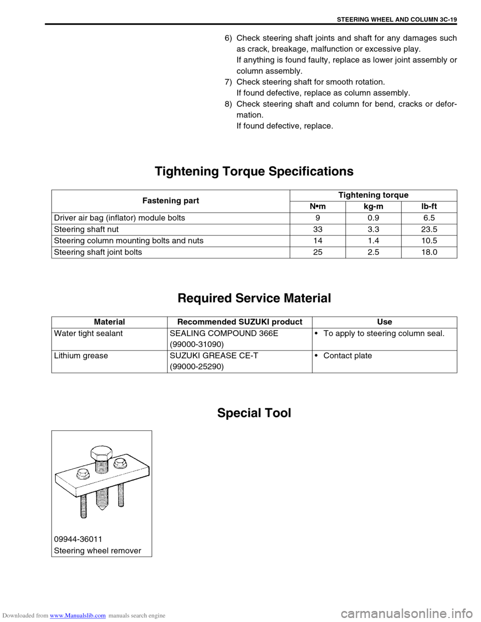
Special Tool
Fastening partTightening torque
Nm kg-m lb-ft
Driver air bag (inflator) module bolts 9 0.9 6.5
Steering shaft nut 33 3.3 23.5
Steering column mounting bolts and nuts 14 1.4 10.5
Steering shaft joint bolts 25 2.5 18.0
Material Recommended SUZUKI product Use
Water tight sealant SEALING COMPOUND 366E
(99000-31090)To apply to steering column seal.
Lithium grease SUZUKI GREASE CE-T
(99000-25290)Contact plate
09944-36011
Steering wheel remover
Page 198 of 687
Downloaded from www.Manualslib.com manuals search engine FRONT SUSPENSION 3D-25
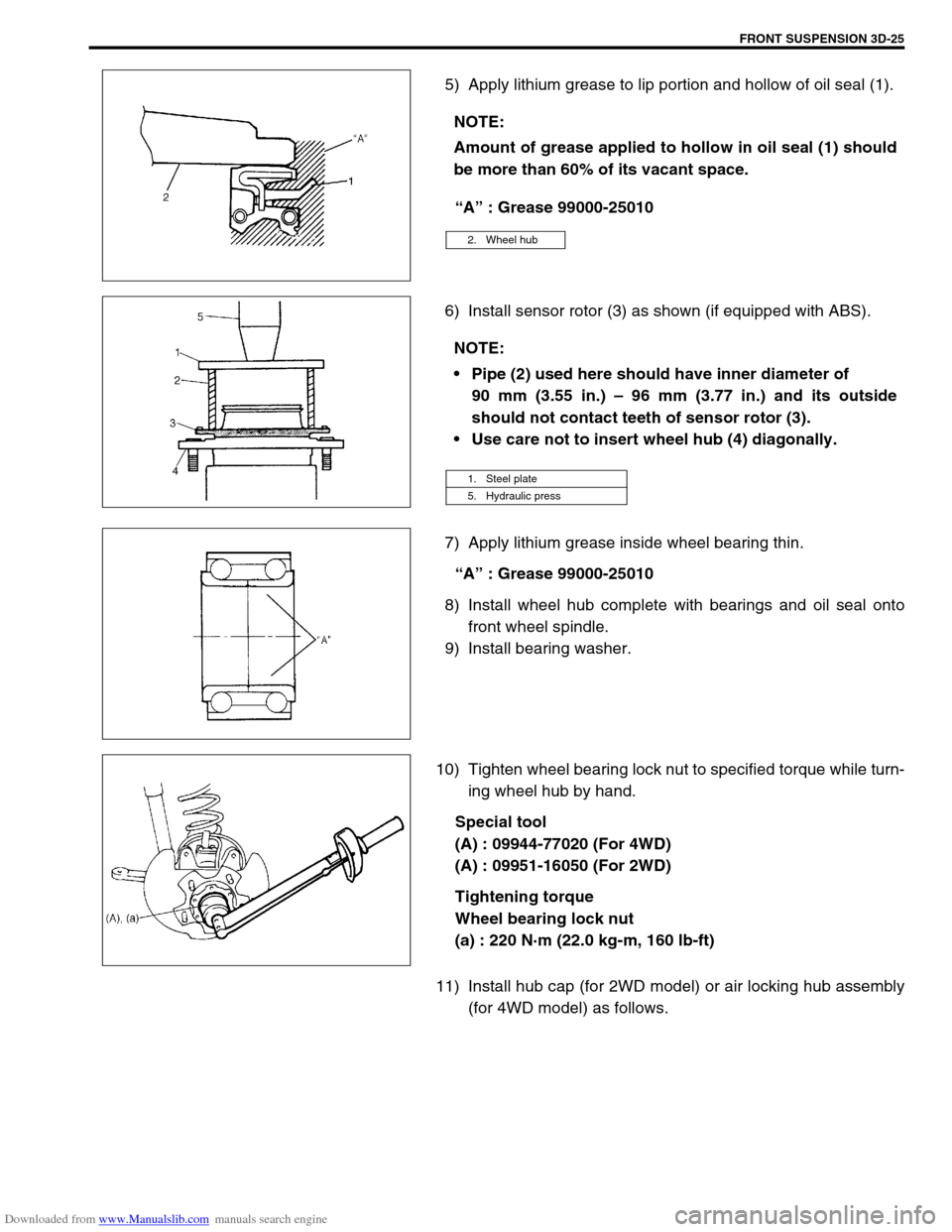
5) Apply lithium grease to lip portion and hollow of oil seal (1).
“A” : Grease 99000-25010
6) Install sensor rotor (3) as shown (if equipped with ABS).
7) Apply lithium grease inside wheel bearing thin.
“A” : Grease 99000-25010
8) Install wheel hub complete with bearings and oil seal onto
front wheel spindle.
9) Install bearing washer.
10) Tighten wheel bearing lock nut to specified torque while turn-
ing wheel hub by hand.
Special tool
(A) : 09944-77020 (For 4WD)
(A) : 09951-16050 (For 2WD)
Tightening torque
Wheel bearing lock nut
(a) : 220 N·m (22.0 kg-m, 160 lb-ft)
11) Install hub cap (for 2WD model) or air locking hub assembly
(for 4WD model) as follows. NOTE:
Amount of grease applied to hollow in oil seal (1) should
be more than 60% of its vacant space.
2. Wheel hub
NOTE:
Pipe (2) used here should have inner diameter of
90 mm (3.55 in.) – 96 mm (3.77 in.) and its outside
should not contact teeth of sensor rotor (3).
Use care not to insert wheel hub (4) diagonally.
1. Steel plate
5. Hydraulic press
Page 199 of 687
Downloaded from www.Manualslib.com manuals search engine 3D-26 FRONT SUSPENSION
For 2WD model:
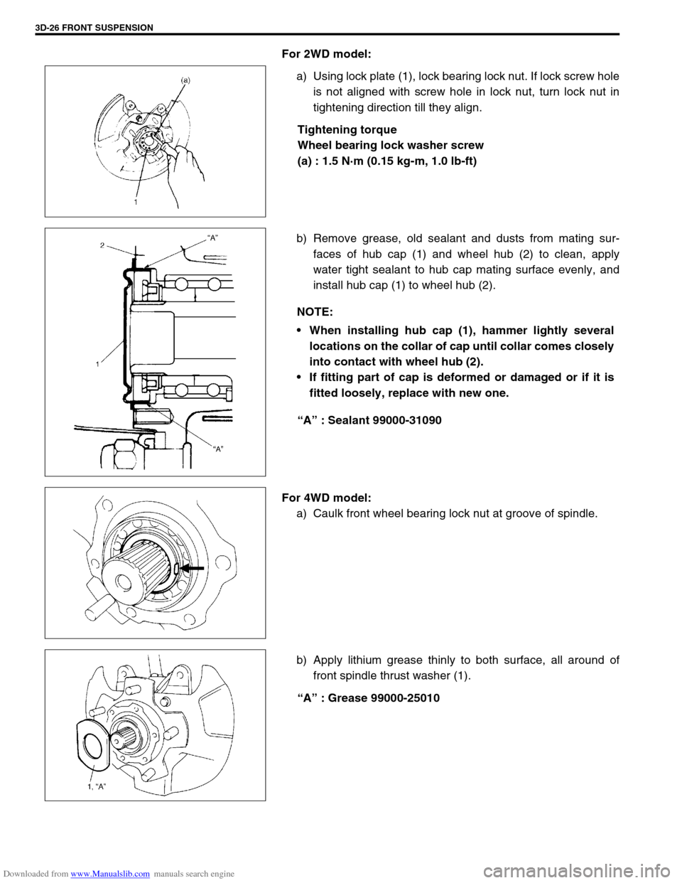
a) Using lock plate (1), lock bearing lock nut. If lock screw hole
is not aligned with screw hole in lock nut, turn lock nut in
tightening direction till they align.
Tightening torque
Wheel bearing lock washer screw
(a) : 1.5 N·m (0.15 kg-m, 1.0 lb-ft)
b) Remove grease, old sealant and dusts from mating sur-
faces of hub cap (1) and wheel hub (2) to clean, apply
water tight sealant to hub cap mating surface evenly, and
install hub cap (1) to wheel hub (2).
“A” : Sealant 99000-31090
For 4WD model:
a) Caulk front wheel bearing lock nut at groove of spindle.
b) Apply lithium grease thinly to both surface, all around of
front spindle thrust washer (1).
“A” : Grease 99000-25010
NOTE:
When installing hub cap (1), hammer lightly several
locations on the collar of cap until collar comes closely
into contact with wheel hub (2).
If fitting part of cap is deformed or damaged or if it is
fitted loosely, replace with new one.
Page 200 of 687
Downloaded from www.Manualslib.com manuals search engine FRONT SUSPENSION 3D-27
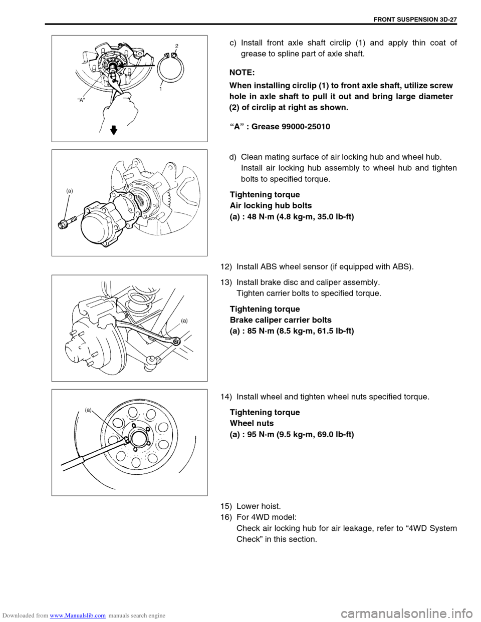
c) Install front axle shaft circlip (1) and apply thin coat of
grease to spline part of axle shaft.
“A” : Grease 99000-25010
d) Clean mating surface of air locking hub and wheel hub.
Install air locking hub assembly to wheel hub and tighten
bolts to specified torque.
Tightening torque
Air locking hub bolts
(a) : 48 N·m (4.8 kg-m, 35.0 lb-ft)
12) Install ABS wheel sensor (if equipped with ABS).
13) Install brake disc and caliper assembly.
Tighten carrier bolts to specified torque.
Tightening torque
Brake caliper carrier bolts
(a) : 85 N·m (8.5 kg-m, 61.5 lb-ft)
14) Install wheel and tighten wheel nuts specified torque.
Tightening torque
Wheel nuts
(a) : 95 N·m (9.5 kg-m, 69.0 lb-ft)
15) Lower hoist.
16) For 4WD model:
Check air locking hub for air leakage, refer to “4WD System
Check” in this section. NOTE:
When installing circlip (1) to front axle shaft, utilize screw
hole in axle shaft to pull it out and bring large diameter
(2) of circlip at right as shown.
Page 203 of 687
Downloaded from www.Manualslib.com manuals search engine 3D-30 FRONT SUSPENSION
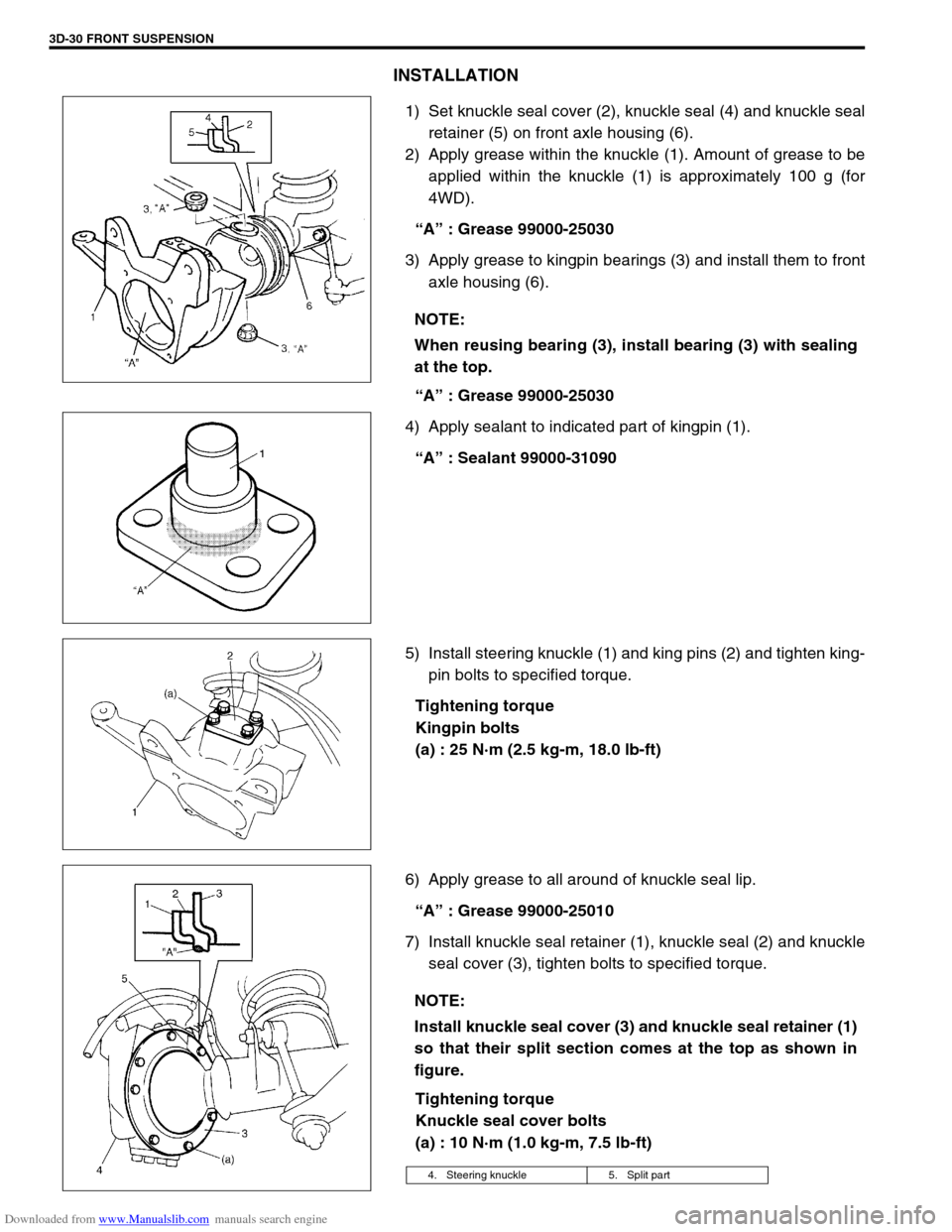
INSTALLATION
1) Set knuckle seal cover (2), knuckle seal (4) and knuckle seal
retainer (5) on front axle housing (6).
2) Apply grease within the knuckle (1). Amount of grease to be
applied within the knuckle (1) is approximately 100 g (for
4WD).
“A” : Grease 99000-25030
3) Apply grease to kingpin bearings (3) and install them to front
axle housing (6).
“A” : Grease 99000-25030
4) Apply sealant to indicated part of kingpin (1).
“A” : Sealant 99000-31090
5) Install steering knuckle (1) and king pins (2) and tighten king-
pin bolts to specified torque.
Tightening torque
Kingpin bolts
(a) : 25 N·m (2.5 kg-m, 18.0 lb-ft)
6) Apply grease to all around of knuckle seal lip.
“A” : Grease 99000-25010
7) Install knuckle seal retainer (1), knuckle seal (2) and knuckle
seal cover (3), tighten bolts to specified torque.
Tightening torque
Knuckle seal cover bolts
(a) : 10 N·m (1.0 kg-m, 7.5 lb-ft) NOTE:
When reusing bearing (3), install bearing (3) with sealing
at the top.
NOTE:
Install knuckle seal cover (3) and knuckle seal retainer (1)
so that their split section comes at the top as shown in
figure.
4. Steering knuckle 5. Split part
Page 204 of 687

Downloaded from www.Manualslib.com manuals search engine FRONT SUSPENSION 3D-31
8) Press-fit spindle bushing (2) to wheel spindle (1) by using
special tool.
Set cut part (4) of spindle bushing (2) as shown in figure
(opposite side of the groove (3) of wheel spindle).
Special tool
(A) : 09922-55131
9) Press-fit spindle oil seal (1) until it becomes flush with wheel
spindle (2) surface by using special tool, and then apply
grease to its lip.
Special tool
(A) : 09944-66020
10) Apply grease to spindle oil seal lip.
“A” : Grease 99000-25010
11) Apply grease to spindle bushing inside surface and flange
(2).
“A” : Grease 99000-25010
12) Install wheel spindle to knuckle, coat their mating surface
with sealant.
“B” : Sealant 99000-31110 or 99000-31090
13) Install wheel spindle (1) and disc dust cover (2) to steering
knuckle. Tighten wheel spindle bolts to specified torque.
Tightening torque
Wheel spindle bolts
(a) : 50 N·m (5.0 kg-m, 36.5 lb-ft)
CAUTION:
As this hole is a part of the passage of the vacuum that
activates the air locking hub, if it is clogged with grease,
the air locking hub cannot be locked or unlocked.
Therefore, be careful not to apply too much grease to
avoid clogging the vacuum passage.
Page 205 of 687
Downloaded from www.Manualslib.com manuals search engine 3D-32 FRONT SUSPENSION
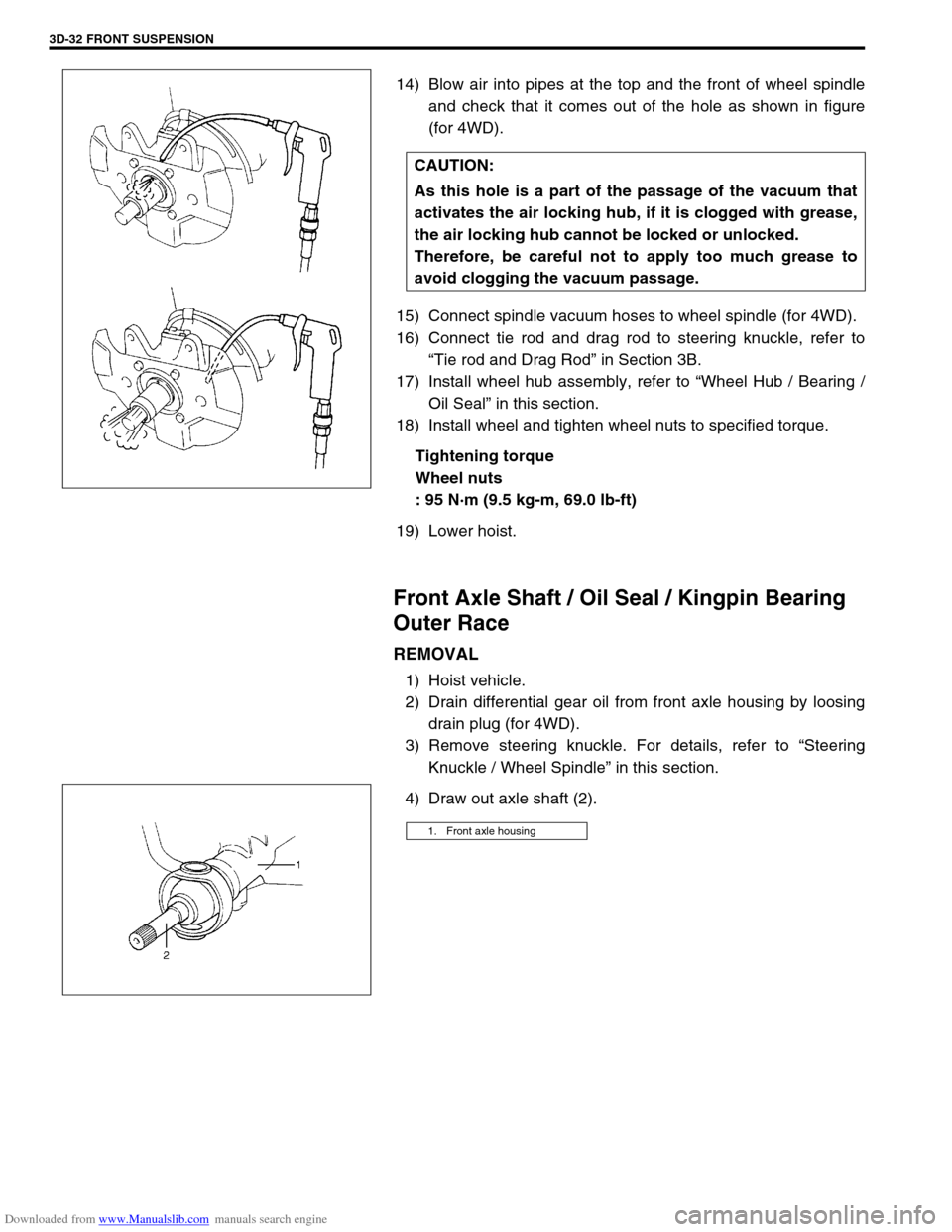
14) Blow air into pipes at the top and the front of wheel spindle
and check that it comes out of the hole as shown in figure
(for 4WD).
15) Connect spindle vacuum hoses to wheel spindle (for 4WD).
16) Connect tie rod and drag rod to steering knuckle, refer to
“Tie rod and Drag Rod” in Section 3B.
17) Install wheel hub assembly, refer to “Wheel Hub / Bearing /
Oil Seal” in this section.
18) Install wheel and tighten wheel nuts to specified torque.
Tightening torque
Wheel nuts
: 95 N·m (9.5 kg-m, 69.0 lb-ft)
19) Lower hoist.
Front Axle Shaft / Oil Seal / Kingpin Bearing
Outer Race
REMOVAL
1) Hoist vehicle.
2) Drain differential gear oil from front axle housing by loosing
drain plug (for 4WD).
3) Remove steering knuckle. For details, refer to “Steering
Knuckle / Wheel Spindle” in this section.
4) Draw out axle shaft (2).CAUTION:
As this hole is a part of the passage of the vacuum that
activates the air locking hub, if it is clogged with grease,
the air locking hub cannot be locked or unlocked.
Therefore, be careful not to apply too much grease to
avoid clogging the vacuum passage.
1. Front axle housing
Page 206 of 687
Downloaded from www.Manualslib.com manuals search engine FRONT SUSPENSION 3D-33
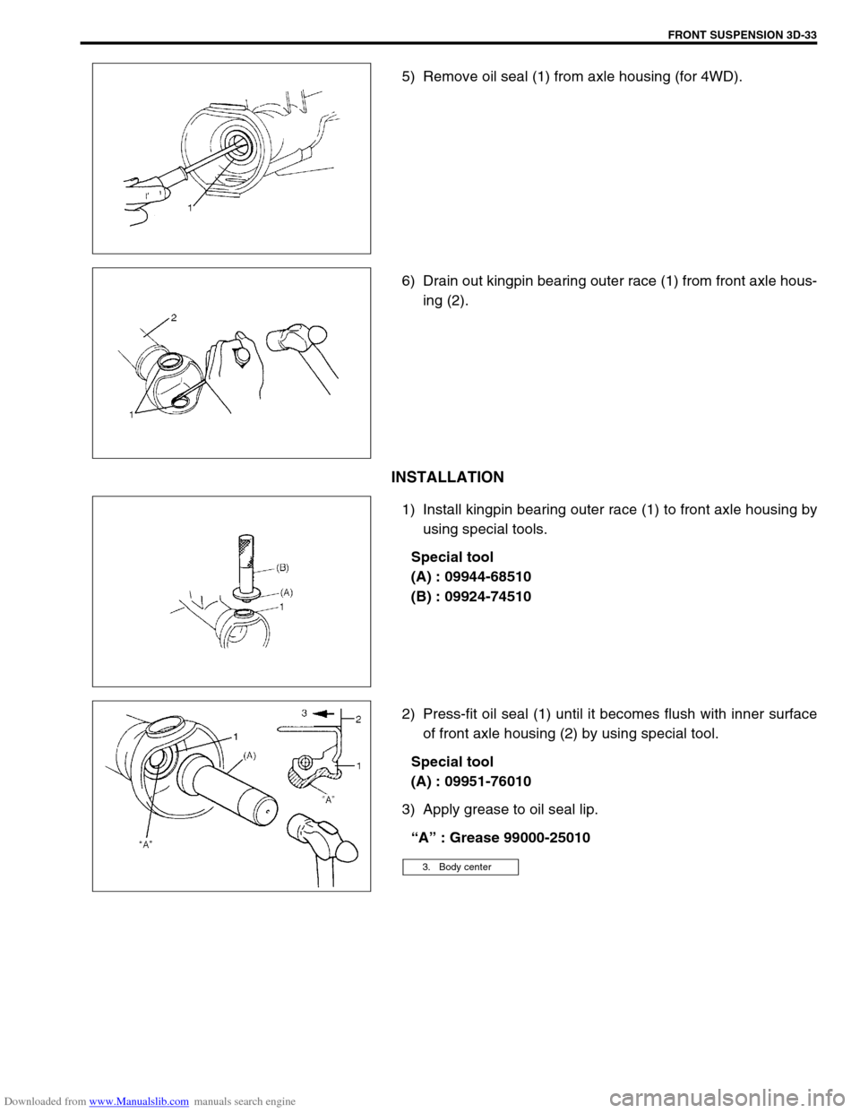
5) Remove oil seal (1) from axle housing (for 4WD).
6) Drain out kingpin bearing outer race (1) from front axle hous-
ing (2).
INSTALLATION
1) Install kingpin bearing outer race (1) to front axle housing by
using special tools.
Special tool
(A) : 09944-68510
(B) : 09924-74510
2) Press-fit oil seal (1) until it becomes flush with inner surface
of front axle housing (2) by using special tool.
Special tool
(A) : 09951-76010
3) Apply grease to oil seal lip.
“A” : Grease 99000-25010
3. Body center
Page 208 of 687

Downloaded from www.Manualslib.com manuals search engine FRONT SUSPENSION 3D-35
2) Apply grease to oil seal lip.
“A” : Grease 99000-25010
3) Install oil seal retainer (1), oil seal (2) and oil seal cover (3) to
steering knuckle (4).
Tighten bolts to specified Torque
Tightening torque
Knuckle seal cover bolts
(a) : 10 N·m (1.0 kg-m, 7.5 lb-ft)
Lateral Rod
REMOVAL
1) Hoist vehicle.
2) Remove mounting bolts of lateral rod (1).
3) Remove lateral rod (1).
INSTALLATION
1) Install lateral rod (1) to vehicle body and front axle housing,
referring to figure for proper installing direction of bolts.
Bolt and nut should not be tightened.
2) Lower hoist and with vehicle in non-loaded condition, tighten
bolt and nut of lateral rod to specified torque.
Tightening torque
Lateral rod bolt and nut
(a) : 90 N·m (9.0 kg-m, 65.0 lb-ft) NOTE:
Install the seal (2) in oil seal retainer (1), bringing the split
part (5) to top side and locating it about 30° off the
matching face of oil seal retainer (1).
NOTE:
For left hand steering vehicle, install lateral rod with its
bending point (2) placed to right side of vehicle.
[A] : Right hand steering vehicle
[B] : Left hand steering vehicle
Page 217 of 687

Downloaded from www.Manualslib.com manuals search engine 3D-44 FRONT SUSPENSION
Tightening Torque Specifications
Required Service Material
Fastening partTightening torque
Nm kg-m lb-ft
Stabilizer mount bracket bolt 20 2.0 14.5
Stabilizer ball joint nut 50 5.0 36.5
Shock absorber lock nut 29 2.9 21.0
Shock absorber lower nut 90 9.0 65.0
Brake caliper carrier bolt 85 8.5 61.5
Wheel bearing lock nut 220 22.0 160.0
Wheel bearing lock washer screw 1.5 0.15 1.0
Air locking hub bolt 48 4.8 35.0
Wheel spindle bolt 50 5.0 36.5
Kingpin bolt 25 2.5 18.0
Knuckle seal cover bolt 10 1.0 7.5
Tie-rod end nut
43 4.3 31.5
Drag-rod end nut (Knuckle side)
Lateral rod bolt and nut
90 9.0 65.0
Leading arm nut
Front differential carrier bolt 23 2.3 17.0
Front propeller shaft flange bolt 50 5.0 36.5
Wheel nut 95 9.5 69.0
Vacuum pipe clamp bolt 5.5 0.55 4.0
MaterialRecommended SUZUKI product
(Part Number)Use
Lithium grease SUZUKI SUPER GREASE (A)
(99000-25010)Knuckle seal / axle shaft oil seal
Recess of wheel spindles
Wheel hub oil seal
Wheel bearing
Spindle thrust washer
Spindle bush (inside and flange
part)
Spindle oil seal
SUZUKI SUPER GREASE (C)
(99000-25030)Kingpin bearing
Axle shaft joint (for 4WD)
Sealant SUZUKI BOND NO. 1215
(99000-31110)Mating surfaces of wheel spindle
and knuckle
Mating surface of differential carrier
and axle housing
Sealing compound SUZUKI SEALING COMPOUND
366E
(99000-31090)Mating surface of wheel spindle and
knuckle
Kingpin
Mating surfaces of hub cap and
wheel hub