grease SUZUKI JIMNY 2005 3.G Service Owner's Guide
[x] Cancel search | Manufacturer: SUZUKI, Model Year: 2005, Model line: JIMNY, Model: SUZUKI JIMNY 2005 3.GPages: 687, PDF Size: 13.38 MB
Page 293 of 687

Downloaded from www.Manualslib.com manuals search engine 5-32 BRAKES
Brake shoe
REMOVAL
1) Remove brake drum referring to “Brake Drum” in this sec-
tion.
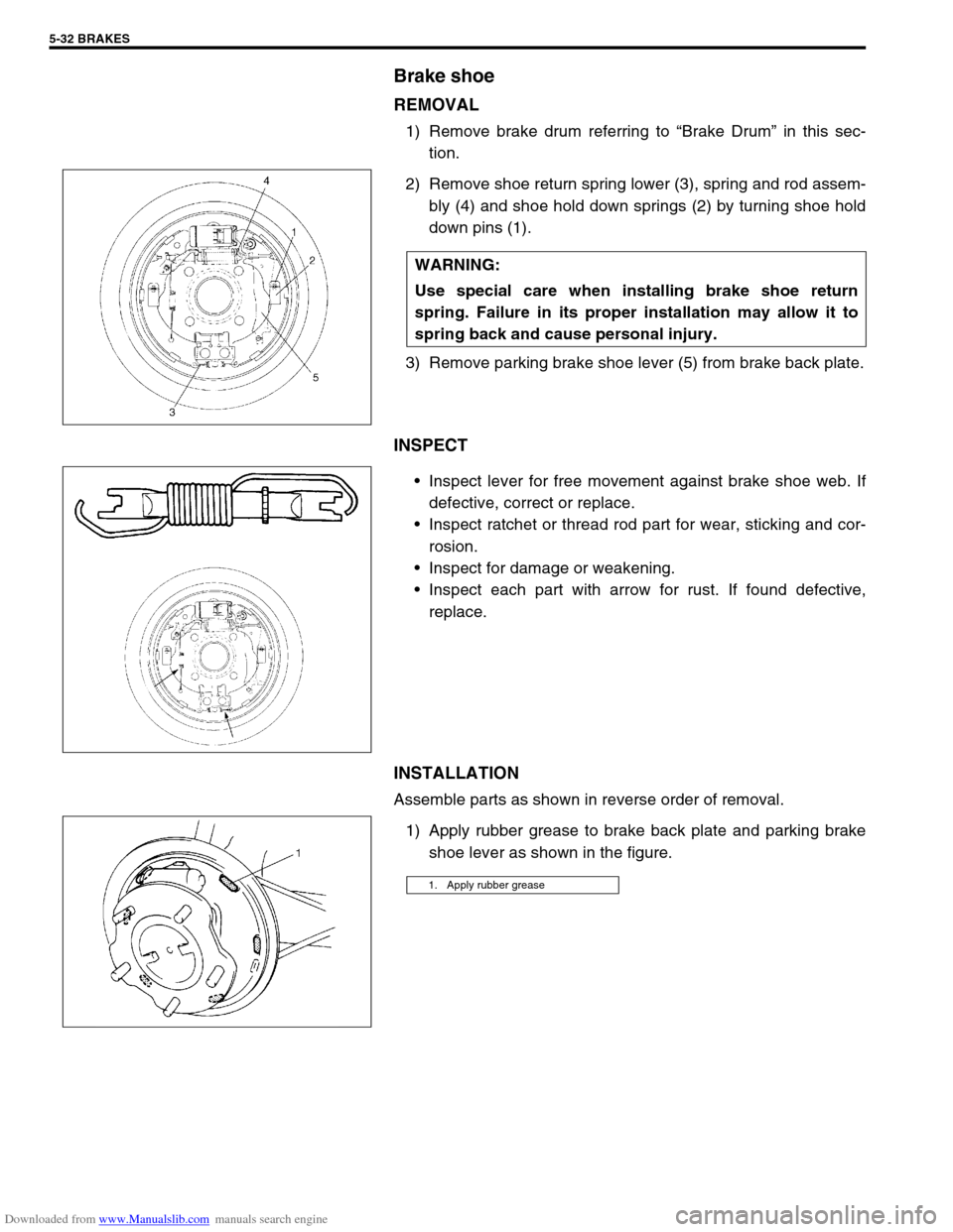
2) Remove shoe return spring lower (3), spring and rod assem-
bly (4) and shoe hold down springs (2) by turning shoe hold
down pins (1).
3) Remove parking brake shoe lever (5) from brake back plate.
INSPECT
Inspect lever for free movement against brake shoe web. If
defective, correct or replace.
Inspect ratchet or thread rod part for wear, sticking and cor-
rosion.
Inspect for damage or weakening.
Inspect each part with arrow for rust. If found defective,
replace.
INSTALLATION
Assemble parts as shown in reverse order of removal.
1) Apply rubber grease to brake back plate and parking brake
shoe lever as shown in the figure. WARNING:
Use special care when installing brake shoe return
spring. Failure in its proper installation may allow it to
spring back and cause personal injury.
1. Apply rubber grease
Page 307 of 687

Downloaded from www.Manualslib.com manuals search engine 5-46 BRAKES
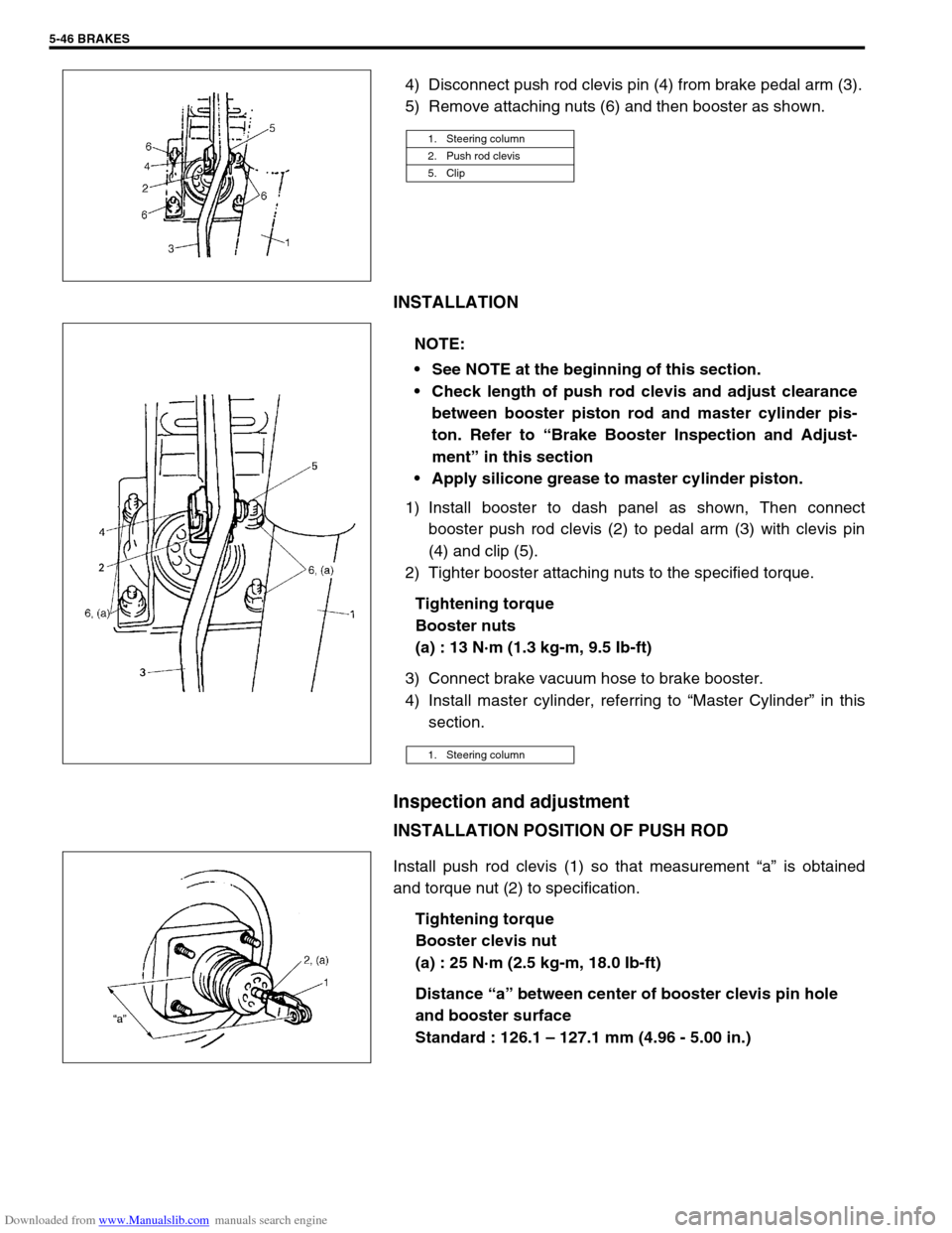
4) Disconnect push rod clevis pin (4) from brake pedal arm (3).
5) Remove attaching nuts (6) and then booster as shown.
INSTALLATION
1) Install booster to dash panel as shown, Then connect
booster push rod clevis (2) to pedal arm (3) with clevis pin
(4) and clip (5).
2) Tighter booster attaching nuts to the specified torque.
Tightening torque
Booster nuts
(a) : 13 N·m (1.3 kg-m, 9.5 Ib-ft)
3) Connect brake vacuum hose to brake booster.
4) Install master cylinder, referring to “Master Cylinder” in this
section.
Inspection and adjustment
INSTALLATION POSITION OF PUSH ROD
Install push rod clevis (1) so that measurement “a” is obtained
and torque nut (2) to specification.
Tightening torque
Booster clevis nut
(a) : 25 N·m (2.5 kg-m, 18.0 Ib-ft)
Distance “a” between center of booster clevis pin hole
and booster surface
Standard : 126.1 – 127.1 mm (4.96 - 5.00 in.)
1. Steering column
2. Push rod clevis
5. Clip
NOTE:
See NOTE at the beginning of this section.
Check length of push rod clevis and adjust clearance
between booster piston rod and master cylinder pis-
ton. Refer to “Brake Booster Inspection and Adjust-
ment” in this section
Apply silicone grease to master cylinder piston.
1. Steering column
Page 665 of 687

Downloaded from www.Manualslib.com manuals search engine 6G-6 CRANKING SYSTEM
DISASSEMBLY AND REASSEMBLY
NOTE:
Make sure to apply grease before assembly, where are indicated “A” in the figure below.
Spare parts have been lubricated.
1. Front housing 6. Over-running clutch 11. Magnetic switch 16. Packing 21. Rear bracket
2. Bush 7. Lever 12. Ball 17. Yoke 22. Rear bush
3. Snap ring 8. Plunger 13. Internal gear 18. Armature 23. Brush spring
4. Pinion stop ring 9. Plate 14. Planetary carrier shaft 19. Brush Apply grease (99000-25010)
5. Pinion gear 10. Seal rubber 15. Planetary gear 20. Brush holder Do not reuse.
Page 671 of 687

Downloaded from www.Manualslib.com manuals search engine 6H-4 CHARGING SYSTEM
When keeping battery on vehicle over a long period of time, follow
instructions given below.
Weekly, start the engine and run it until it reaches normal
operating temperature with engine speed of 2,000 to 3,000
rpm. Make sure all electric switches are off before storing the
vehicle.
Recharge the battery twice a month to prevent it from dis-
charging excessively. This is especially important when
ambient temperature is low.
The battery discharges even when it is not used, while vehi-
cles are being stored. Battery electrolyte can freeze and bat-
tery case can crack at cold ambient condition if battery is not
properly charged.
2) Keep the battery cable connections clean.
The cable connections, particularly at the positive (+) termi-
nal post, tend to become corroded. The product of corrosion,
or rust, on the mating faces of conductors resists the flow of
current.
Clean the terminals and fittings periodically to ensure good
metal-to-metal contact, and grease the connections after
each cleaning to protect them against rusting.
3) Be always in the know as to the state of charge of the bat-
tery. The simplest way to tell the state of charge is to carry
out a hydrometer test. The hydrometer is an instrument for
measuring the specific gravity (S.G.) of the battery electro-
lyte. The S.G. of the electrolyte is indicative of the state of
charge. Refer to “HYDROMETER TEST” in this section.
Generator
The generator is a small and high performance type with an IC regulator incorporated.
The internal components are connected electrically as shown below figure.
The generator features are as follows:
Solid state regulator is mounted inside the generator.
All regulator components are enclosed into a solid mold.
This unit along with the brush holder assembly is attached to the rear housing.
The IC regulator uses integrated circuits and controls the voltage produced by the generator, and the volt-
age setting cannot be adjusted.
The generator rotor bearings contain enough grease to eliminate the need for periodic lubrication. Two
brushes carry current through the two slip rings to the field coil mounted on the rotor, and under normal con-
ditions will provide long period of attention-free service.
The stator windings are assembled on the inside of a laminated core that forms part of the generator frame.
A condenser mounted in the rear housing suppresses radio noise.