turn signal SUZUKI JIMNY 2005 3.G Service User Guide
[x] Cancel search | Manufacturer: SUZUKI, Model Year: 2005, Model line: JIMNY, Model: SUZUKI JIMNY 2005 3.GPages: 687, PDF Size: 13.38 MB
Page 396 of 687

Downloaded from www.Manualslib.com manuals search engine ENGINE GENERAL INFORMATION AND DIAGNOSIS 6-39
For TYPE B (See NOTE)
E174Blank––
5 Overdrive cut signal (A/T)0 – 1.0 VIgnition switch ON and ECT less than
60 °C
10 – 14 VIgnition switch ON and ECT more than
60 °C
6 D-range idle up signal (A/T)10 – 14 VIgnition switch ON and shift select switch
in other than P and N range
0 – 1.6 VIgnition switch ON and shift select switch
in P and N range
7 Stop lamp switch0 VIgnition switch ON
Stop lamp switch OFF
10 – 14 VIgnition switch ON
Stop lamp switch ON
8–– –
9 Ignition switch 10 – 14 V Ignition switch ON
10–– –
11 Vehicle speed sensordeflect
between
0 – 1.6 and
4 – 14 VIgnition switch ON and rear right wheel
turned slowly with rear left wheel locked
12 ABS signal (if equipped) 10 – 14 V Ignition switch ON
13 Engine start signal 6 – 14 V While engine cranking
14–– –
15–– –
16 Rear defogger switch (if equipped)10 – 14 V Ignition switch ON and rear defogger
switch ON
0 – 1.3 V Ignition switch ON and rear defogger
switch OFF
17 A/T failure signal (with immobilizer
indicator lamp) (A/T)–– TERMINAL
NO.CIRCUIT NORMAL
VOLTAGECONDITION
NOTE:
See NOTE in “ECM TERMINAL VOLTAGE VALUES TABLE” for applicable model.
TERMINAL
NO.CIRCUIT NORMAL
VOLTAGECONDITION
E171 A/C evaporator temp. sensor 2.0 – 2.3 VIgnition switch ON
A/C evaporator temp. sensor at 25 °C
(77 °F)
2 R-range signal (A/T)10 – 14 VIgnition switch ON and shift select switch
in R range
0 – 1.3 VIgnition switch ON and shift select switch
in other than R range
3Blank––
4Blank––
Page 405 of 687
Downloaded from www.Manualslib.com manuals search engine 6-48 ENGINE GENERAL INFORMATION AND DIAGNOSIS
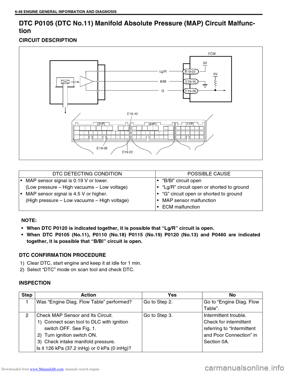
DTC P0105 (DTC No.11) Manifold Absolute Pressure (MAP) Circuit Malfunc-
tion
CIRCUIT DESCRIPTION
DTC CONFIRMATION PROCEDURE
1) Clear DTC, start engine and keep it at idle for 1 min.
2) Select “DTC” mode on scan tool and check DTC.
INSPECTION
DTC DETECTING CONDITION POSSIBLE CAUSE
MAP sensor signal is 0.19 V or lower.
(Low pressure – High vacuums – Low voltage)
MAP sensor signal is 4.5 V or higher.
(High pressure – Low vacuums – High voltage)“B/Bl” circuit open
“Lg/R” circuit open or shorted to ground
“G” circuit open or shorted to ground
MAP sensor malfunction
ECM malfunction
NOTE:
When DTC P0120 is indicated together, it is possible that “Lg/R” circuit is open.
When DTC P0105 (No.11), P0110 (No.18) P0115 (No.19) P0120 (No.13) and P0460 are indicated
together, it is possible that “B/Bl” circuit is open.
Step Action Yes No
1Was “Engine Diag. Flow Table” performed? Go to Step 2. Go to “Engine Diag. Flow
Table”.
2 Check MAP Sensor and Its Circuit.
1) Connect scan tool to DLC with ignition
switch OFF. See Fig. 1.
2) Turn ignition switch ON.
3) Check intake manifold pressure.
Is it 126 kPa (37.2 inHg) or 0 kPa (0 inHg)?Go to Step 3. Intermittent trouble.
Check for intermittent
referring to “Intermittent
and Poor Connection” in
Section 0A.
Page 422 of 687

Downloaded from www.Manualslib.com manuals search engine ENGINE GENERAL INFORMATION AND DIAGNOSIS 6-65
6) Repeat above steps 5) 4 times.
7) Increase vehicle speed to about 50 mph (80 km/h) in 3rd gear or 2 range.
8) Release accelerator pedal and with engine brake applied, keep vehicle coasting (fuel cut condition) for
10sec. or more.
9) Stop vehicle (don’t turn ignition switch OFF) and run engine at idle for 2 min. After this step 9), if “Oxygen
Sensor Monitoring TEST COMPLETED” is displayed in “READINESS TESTS” mode and DTC is not dis-
played in “DTC” mode, confirmation test is completed.
If “TEST NOT COMPLTD” is still being displayed, proceed to next step 10).
10) Drive vehicle under usual driving condition for 10 min. (or vehicle is at a stop and run engine at idle for 10
min. or longer)
11) Stop vehicle (don’t turn ignition switch OFF). Confirm test results according to “Test Result Confirmation
Flow Table” in “DTC CONFIRMATION PROCEDURE” of DTC P0420.
INSPECTION
*Usual driving : Driving at 30 – 40 mph, 50 – 60 km/h including short stop according to traffic signal. (under driving condition other than high-load, high-engine
speed, rapid accelerating and decelerating)
Step Action Yes No
1Was “Engine Diag. Flow Table” performed? Go to Step 2. Go to “Engine Diag. Flow
Table”.
2 Check exhaust system for leakage, loose con-
nection and damage.
Is it good condition?Go to Step 3. Repair or replace.
3 Check HO2S-2 and Its Circuit.
Was HO2S-2 output voltage indicated on scan
tool in step 3) of DTC confirmation test less
than 1.275 V?Go to Step 4.“B/Bl” or “W” circuit open
or HO2S-2 malfunction.
4 Check Short Term Fuel Trim.
Did short term fuel trim very within –20 – + 20%
range in step 3) of DTC confirmation test?Check “W” and “B/Bl” wire
for open and short, and
connection for poor con-
nection. If wire and con-
nection are OK, replace
HO2S-2.Check fuel system. Go to
DTC P0171 / P0172 Diag.
Flow Table.
Page 437 of 687

Downloaded from www.Manualslib.com manuals search engine 6-80 ENGINE GENERAL INFORMATION AND DIAGNOSIS
INSPECTION
Step Action Yes No
1Was “Engine Diag. Flow Table” performed? Go to Step 2. Go to “Engine Diag.
Flow Table”.
2 Check CKP Sensor and connector for proper
installation.
Is CKP sensor installed properly and connector
connected securely?Go to Step 3. Correct.
3 Check Wire Harness and Connection.
1) Disconnect connector from CKP sensor.
2) Check for proper connection to CKP sensor at
each terminal.
3) If OK, turn ignition switch ON and check for
voltage at each terminal of sensor connector
disconnected. See Fig. 1.
Terminal “B+” : 10 – 14 V
Terminal “Vout” : 4 – 5 V
Terminal “GND” : 0 V
Is check result satisfactory?Go to Step 5. Go to Step 4.
4 Was terminal “Vout” voltage out of specification in
Step 3 check?“G/R” wire open, short or
poor connection.
If wire and connection are
OK, substitute a known-
good ECM and recheck.“Bl/B” or “B/R” wire
open, short or poor
connection.
5 Check Ground Circuit for Open.
1) Turn ignition switch OFF.
2) Check for continuity between “GND” terminal
of CKP sensor connector and engine ground.
Is continuity indicated?Go to Step 6.“B/R” wire open or
poor ground connec-
tion.
6 Check CKP Sensor for Operation.
1) Remove CKP sensor from sensor case.
2) Remove metal particles on end face of CKP
sensor, if any.
3) Connect each connector to ECM and CKP
sensor.
4) Turn ignition switch ON.
5) Check for voltage at terminal E19-23 of con-
nector connected to ECM by passing magnetic
substance (iron) (1) while keeping approxi-
mately 1 mm (0.03 in.) gap with respect to end
face of CKP sensor. See Fig. 2 and 3.
Does voltage vary from low (0 – 1 V) to high (4 – 5
V) or from high to low?Go to Step 7. Replace CKP sensor.
7 Check signal rotor for the following. See Fig. 4.
Damage
No foreign material attached
Is it in good condition?Intermittent trouble or
faulty ECM.
Check for intermittent
referring to “Intermittent
and Poor Connection” in
Section 0A.Clean rotor teeth or
replace CKP sensor.
Page 440 of 687

Downloaded from www.Manualslib.com manuals search engine ENGINE GENERAL INFORMATION AND DIAGNOSIS 6-83
INSPECTION
Step Action Yes No
1Was “Engine Diag. Flow Table” performed? Go to Step 2. Go to “Engine Diag.
Flow Table”.
2 Check CMP Sensor and connector for proper installa-
tion.
Is CMP sensor installed properly and connector con-
nected securely?Go to Step 3. Correct.
3 Check Wire Harness and Connection.
1) Disconnect connector from CMP sensor.
2) Check for proper connection to CMP sensor at
each terminal.
3) If OK, turn ignition switch ON and check for volt-
age at each terminal of sensor connector discon-
nected. See Fig. 1.
Terminal “B+” : 10 – 14 V
Terminal “Vout” : 4 – 5 V
Terminal “GND” : 0 V
Is check result satisfactory?Go to Step 5. Go to Step 4.
4 Was terminal “Vout” voltage out of specification in
Step 3 check?“W” wire open, short or
poor connection.
If wire and connection
are OK, substitute a
known-good ECM and
recheck.“Bl/B” or “B/R” wire
open, short or poor
connection.
5 Check Ground Circuit for Open.
1) Turn ignition switch OFF.
2) Check for continuity between “GND” terminal of
CMP sensor connector and engine ground.
Is continuity indicated?Go to Step 6.“B/R” wire open or
poor ground connec-
tion.
6 Check CMP Sensor for Operation.
1) Remove CMP sensor from sensor case.
2) Remove metal particles on end face of CMP sen-
sor, if any.
3) Connect each connector to ECM and CMP sensor.
4) Turn ignition switch ON.
5) Check for voltage at terminal E19-11 of connector
connected to ECM by passing magnetic sub-
stance (iron) (1) while keeping approximately 1
mm (0.03 in.) gap with respect to end face of CMP
sensor. See Fig. 2 and 3.
Does voltage vary from low (0 – 1 V) to high (4 – 5 V)
or from high to low?Go to Step 7. Replace CMP sen-
sor.
7 Check signal rotor for the following.
See Fig. 4.
Damage
No foreign material attached
Is it in good condition?Intermittent trouble or
faulty ECM.
Check for intermittent
referring to “Intermittent
and Poor Connection” in
Section 0A.Clean rotor teeth or
replace CMP sensor.
Page 449 of 687
Downloaded from www.Manualslib.com manuals search engine 6-92 ENGINE GENERAL INFORMATION AND DIAGNOSIS
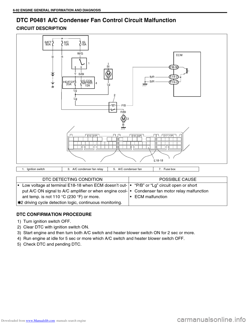
DTC P0481 A/C Condenser Fan Control Circuit Malfunction
CIRCUIT DESCRIPTION
DTC CONFIRMATION PROCEDURE
1) Turn ignition switch OFF.
2) Clear DTC with ignition switch ON.
3) Start engine and then turn both A/C switch and heater blower switch ON for 2 sec or more.
4) Run engine at idle for 5 sec or more which A/C switch and heater blower switch OFF.
5) Check DTC and pending DTC.
1. Ignition switch 3. A/C condenser fan relay 5. A/C condenser fan 7. Fuse box
DTC DETECTING CONDITION POSSIBLE CAUSE
Low voltage at terminal E18-18 when ECM doesn’t out-
put A/C ON signal to A/C amplifier or when engine cool-
ant temp. is not 110 °C (230 °F) or more.
✱
✱✱ ✱2 driving cycle detection logic, continuous monitoring.“P/B” or “Lg” circuit open or short
Condenser fan motor relay malfunction
ECM malfunction
Page 452 of 687
![SUZUKI JIMNY 2005 3.G Service User Guide Downloaded from www.Manualslib.com manuals search engine ENGINE GENERAL INFORMATION AND DIAGNOSIS 6-95
INSPECTION
[A] Fig. 1 for Step 5 / [B] Fig. 2 for Step 4 and Step 6Step Action Yes No
1Was “Eng SUZUKI JIMNY 2005 3.G Service User Guide Downloaded from www.Manualslib.com manuals search engine ENGINE GENERAL INFORMATION AND DIAGNOSIS 6-95
INSPECTION
[A] Fig. 1 for Step 5 / [B] Fig. 2 for Step 4 and Step 6Step Action Yes No
1Was “Eng](/img/20/7588/w960_7588-451.png)
Downloaded from www.Manualslib.com manuals search engine ENGINE GENERAL INFORMATION AND DIAGNOSIS 6-95
INSPECTION
[A] Fig. 1 for Step 5 / [B] Fig. 2 for Step 4 and Step 6Step Action Yes No
1Was “Engine Diag. Flow Table” performed? Go to Step 2. Go to “Engine Diag. Flow
Table”.
2 Does speedometer indicate vehicle speed? Go to Step 3. Go to Step 5.
3 Check Vehicle Speed Signal.
Is vehicle speed displayed on scan tool in step
2) and 3) of DTC confirmation procedure?Intermittent trouble or
faulty ECM.
Check for intermittent
referring to “Intermittent
and Poor Connection” in
Section 0A.Go to Step 4.
4 1) Turn ignition switch to OFF position.
2) Disconnect combination meter connec-
tors.Refer to Section 8.
3) Turn ignition switch to ON position, without
running engine.
4) Measure voltage from terminal “c” of VSS
connector to ground. See Fig.2.
Is voltage within 4 – 5 V?Faulty speedometer.“Y” or “Y/G” wire open or
short.
Poor connection of ECM
connector terminal.
If OK, substitute a known-
good ECM and recheck.
5 1) With ignition switch at OFF position, discon-
nect VSS connector.
2) Turn ignition switch to ON position, without
running engine.
3) Measure voltage from terminal “a” to “b” of
VSS connector. See Fig.1.
Is voltage within 10 – 14 V?Go to Step 6.“Bl/B” or “B/Or” wire open
or short.
6 1) Measure voltage from terminal “c” of VSS
connector to ground. See Fig.2.
Is voltage more than 4 V?Go to Step 7.“Y” or “Y/G” wire open or
short.
Poor connection of ECM
connector terminal.
If OK, substitute a known-
good ECM and recheck.
7 1) Remove VSS.
2) Visually inspect VSS sensor signal rotor for
damage.
Was any damage found?Faulty VSS signal rotor. Poor connection of VSS
connector terminal.
If OK, substitute a known-
good VSS and recheck.
Page 453 of 687
Downloaded from www.Manualslib.com manuals search engine 6-96 ENGINE GENERAL INFORMATION AND DIAGNOSIS
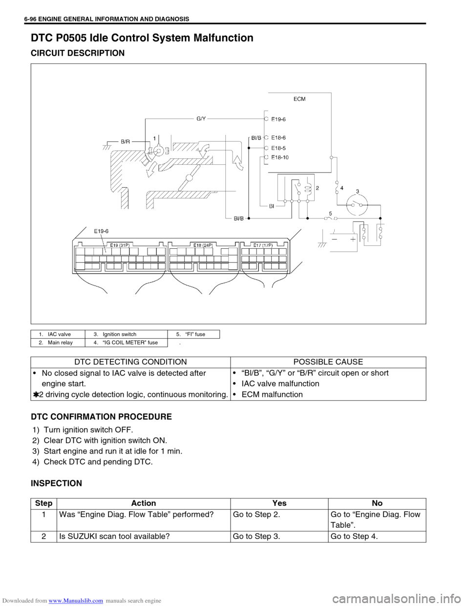
DTC P0505 Idle Control System Malfunction
CIRCUIT DESCRIPTION
DTC CONFIRMATION PROCEDURE
1) Turn ignition switch OFF.
2) Clear DTC with ignition switch ON.
3) Start engine and run it at idle for 1 min.
4) Check DTC and pending DTC.
INSPECTION
1. IAC valve 3. Ignition switch 5.“FI” fuse
2. Main relay 4.“IG COIL METER” fuse .
DTC DETECTING CONDITION POSSIBLE CAUSE
No closed signal to IAC valve is detected after
engine start.
✱
✱✱ ✱2 driving cycle detection logic, continuous monitoring.“Bl/B”, “G/Y” or “B/R” circuit open or short
IAC valve malfunction
ECM malfunction
Step Action Yes No
1Was “Engine Diag. Flow Table” performed? Go to Step 2. Go to “Engine Diag. Flow
Table”.
2 Is SUZUKI scan tool available? Go to Step 3. Go to Step 4.
Page 458 of 687
Downloaded from www.Manualslib.com manuals search engine ENGINE GENERAL INFORMATION AND DIAGNOSIS 6-101
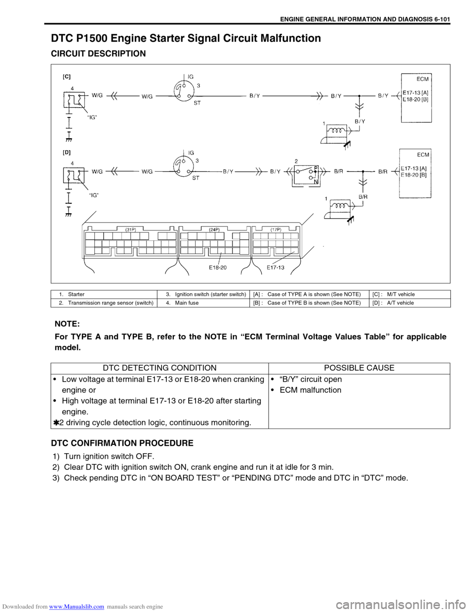
DTC P1500 Engine Starter Signal Circuit Malfunction
CIRCUIT DESCRIPTION
DTC CONFIRMATION PROCEDURE
1) Turn ignition switch OFF.
2) Clear DTC with ignition switch ON, crank engine and run it at idle for 3 min.
3) Check pending DTC in “ON BOARD TEST” or “PENDING DTC” mode and DTC in “DTC” mode.
1. Starter 3. Ignition switch (starter switch) [A] : Case of TYPE A is shown (See NOTE) [C] : M/T vehicle
2. Transmission range sensor (switch) 4. Main fuse [B] : Case of TYPE B is shown (See NOTE) [D] : A/T vehicle
NOTE:
For TYPE A and TYPE B, refer to the NOTE in “ECM Terminal Voltage Values Table” for applicable
model.
DTC DETECTING CONDITION POSSIBLE CAUSE
Low voltage at terminal E17-13 or E18-20 when cranking
engine or
High voltage at terminal E17-13 or E18-20 after starting
engine.
✱
✱✱ ✱2 driving cycle detection logic, continuous monitoring.“B/Y” circuit open
ECM malfunction
Page 462 of 687
Downloaded from www.Manualslib.com manuals search engine ENGINE GENERAL INFORMATION AND DIAGNOSIS 6-105
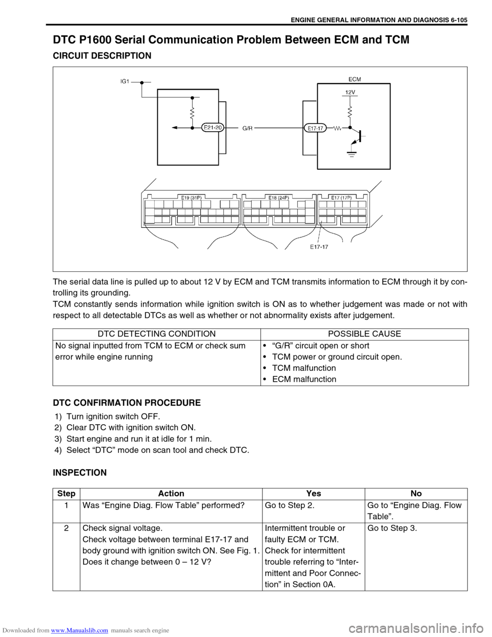
DTC P1600 Serial Communication Problem Between ECM and TCM
CIRCUIT DESCRIPTION
The serial data line is pulled up to about 12 V by ECM and TCM transmits information to ECM through it by con-
trolling its grounding.
TCM constantly sends information while ignition switch is ON as to whether judgement was made or not with
respect to all detectable DTCs as well as whether or not abnormality exists after judgement.
DTC CONFIRMATION PROCEDURE
1) Turn ignition switch OFF.
2) Clear DTC with ignition switch ON.
3) Start engine and run it at idle for 1 min.
4) Select “DTC” mode on scan tool and check DTC.
INSPECTION
DTC DETECTING CONDITION POSSIBLE CAUSE
No signal inputted from TCM to ECM or check sum
error while engine running“G/R” circuit open or short
TCM power or ground circuit open.
TCM malfunction
ECM malfunction
Step Action Yes No
1Was “Engine Diag. Flow Table” performed? Go to Step 2. Go to “Engine Diag. Flow
Table”.
2 Check signal voltage.
Check voltage between terminal E17-17 and
body ground with ignition switch ON. See Fig. 1.
Does it change between 0 – 12 V?Intermittent trouble or
faulty ECM or TCM.
Check for intermittent
trouble referring to “Inter-
mittent and Poor Connec-
tion” in Section 0A.Go to Step 3.