SUZUKI JIMNY 2005 3.G Service Workshop Manual
Manufacturer: SUZUKI, Model Year: 2005, Model line: JIMNY, Model: SUZUKI JIMNY 2005 3.GPages: 687, PDF Size: 13.38 MB
Page 191 of 687

Downloaded from www.Manualslib.com manuals search engine 3D-18 FRONT SUSPENSION
2) When installing stabilizer, loosely assemble all components
while insuring that stabilizer is centered, side-to-side.
3) Tighten stabilizer bracket bolts (2) and stabilizer ball joint
nuts to specified torque.
Tightening torque
Stabilizer mount bracket bolts
(a) : 20 N·m (2.0 kg-m, 14.5 lb-ft)
Stabilizer ball joint nuts
(b) : 50 N·m (5.0 kg-m, 36.5 lb-ft)
4) Install front bumper.
5) Lower hoist.NOTE:
For correct installation of stabilizer bar, side-to-side, be
sure that color paint (1) on stabilizer bar aligns with
mount bush, both right and left, as shown.
NOTE:
Tighten stabilizer mount bracket bolts (2) with vehicle
hoisted a little in non-load condition.
3. Stabilizer ball joint
4. Front axle housing
Page 192 of 687
Downloaded from www.Manualslib.com manuals search engine FRONT SUSPENSION 3D-19
Front Shock Absorber
REMOVAL
1) Hoist vehicle.
2) Support front axle housing by using floor jack to prevent it
from lowering, refer to “When Using Floor Jack” under “Vehi-
cle Lifting Points” in Section 0A.
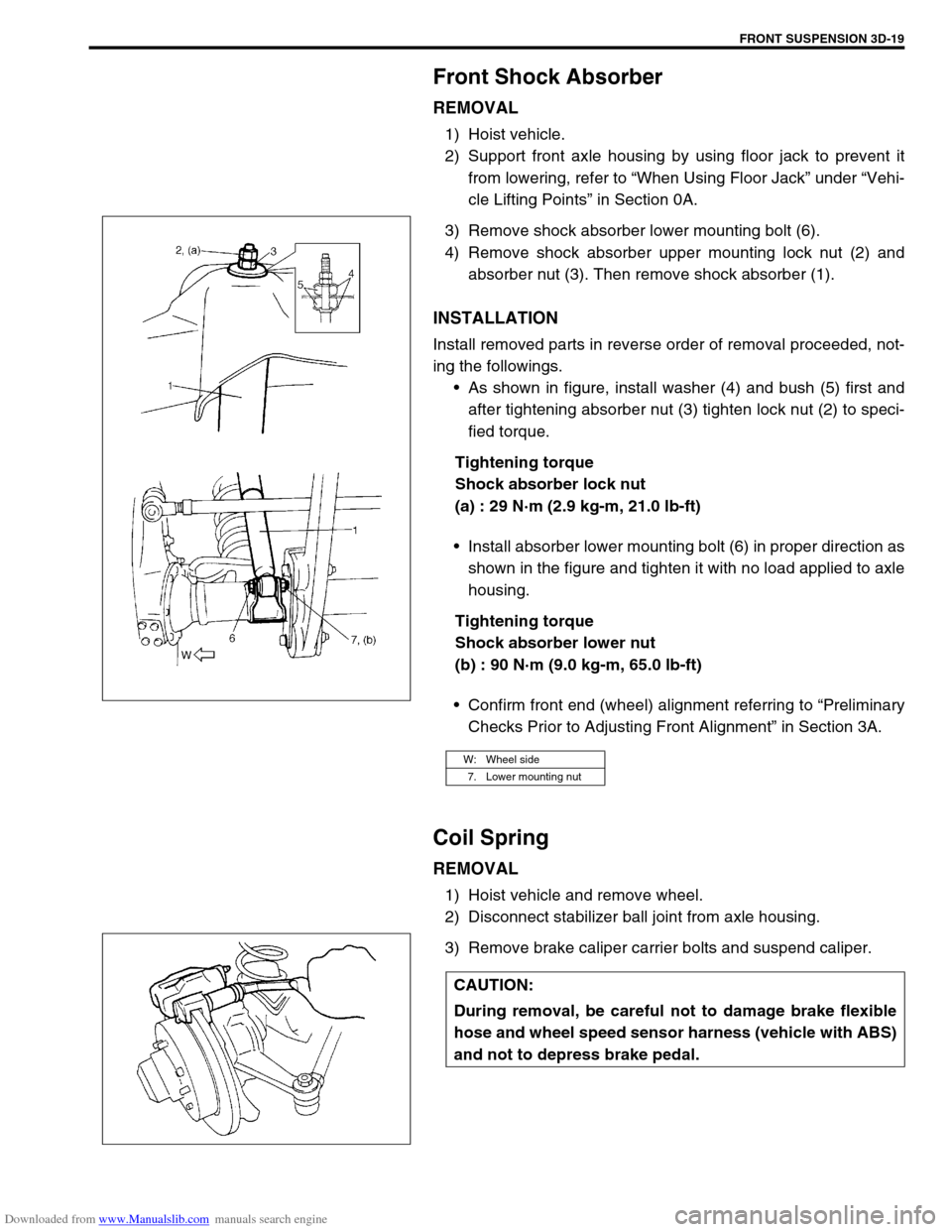
3) Remove shock absorber lower mounting bolt (6).
4) Remove shock absorber upper mounting lock nut (2) and
absorber nut (3). Then remove shock absorber (1).
INSTALLATION
Install removed parts in reverse order of removal proceeded, not-
ing the followings.
As shown in figure, install washer (4) and bush (5) first and
after tightening absorber nut (3) tighten lock nut (2) to speci-
fied torque.
Tightening torque
Shock absorber lock nut
(a) : 29 N·m (2.9 kg-m, 21.0 lb-ft)
Install absorber lower mounting bolt (6) in proper direction as
shown in the figure and tighten it with no load applied to axle
housing.
Tightening torque
Shock absorber lower nut
(b) : 90 N·m (9.0 kg-m, 65.0 lb-ft)
Confirm front end (wheel) alignment referring to “Preliminary
Checks Prior to Adjusting Front Alignment” in Section 3A.
Coil Spring
REMOVAL
1) Hoist vehicle and remove wheel.
2) Disconnect stabilizer ball joint from axle housing.
3) Remove brake caliper carrier bolts and suspend caliper.
W: Wheel side
7. Lower mounting nut
CAUTION:
During removal, be careful not to damage brake flexible
hose and wheel speed sensor harness (vehicle with ABS)
and not to depress brake pedal.
Page 193 of 687

Downloaded from www.Manualslib.com manuals search engine 3D-20 FRONT SUSPENSION
4) Support front axle housing by using floor jack.
5) Remove shock absorber lower mounting bolt (1).
6) Lower front axle housing (2) gradually as far down as where
coil spring (1) can be removed.
7) Remove coil spring (1).
INSTALLATION
Install removed parts in reverse order of removal procedures, not-
ing the followings.
1) Install coil spring (3).
2) Install absorber lower mounting bolt, refer to “Front Shock
Absorber” in this section.
3) Install caliper assembly and tighten caliper bolts to specified
torque.
Tightening torque
Brake caliper carrier bolts
(a) : 85 N·m (8.5 kg-m, 61.5 lb-ft)
4) Connect stabilizer ball joint to axle housing and tighten nut
referring to “Stabilizer Bar” in this section for tightening
torque specification. NOTE:
When supporting axle housing, it should be in non-load
condition.
NOTE:
Make sure that coil spring direction as shown.
When seating coil spring, mate spring end with
stepped part (4) of lower spring seat (2).
1. Front axle housing
U : Upper side
A : Small
B : Large
Page 194 of 687
Downloaded from www.Manualslib.com manuals search engine FRONT SUSPENSION 3D-21
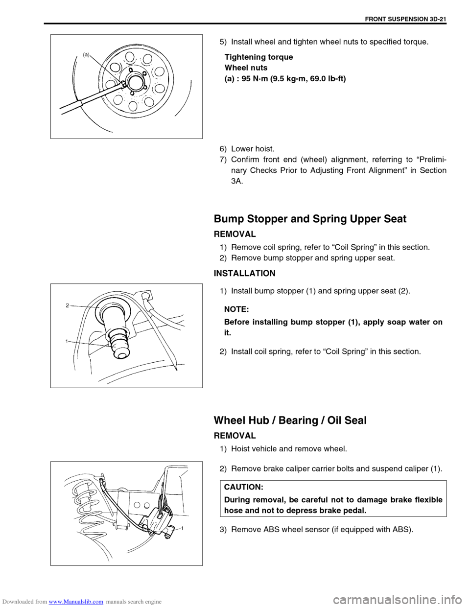
5) Install wheel and tighten wheel nuts to specified torque.
Tightening torque
Wheel nuts
(a) : 95 N·m (9.5 kg-m, 69.0 lb-ft)
6) Lower hoist.
7) Confirm front end (wheel) alignment, referring to “Prelimi-
nary Checks Prior to Adjusting Front Alignment” in Section
3A.
Bump Stopper and Spring Upper Seat
REMOVAL
1) Remove coil spring, refer to “Coil Spring” in this section.
2) Remove bump stopper and spring upper seat.
INSTALLATION
1) Install bump stopper (1) and spring upper seat (2).
2) Install coil spring, refer to “Coil Spring” in this section.
Wheel Hub / Bearing / Oil Seal
REMOVAL
1) Hoist vehicle and remove wheel.
2) Remove brake caliper carrier bolts and suspend caliper (1).
3) Remove ABS wheel sensor (if equipped with ABS).
NOTE:
Before installing bump stopper (1), apply soap water on
it.
CAUTION:
During removal, be careful not to damage brake flexible
hose and not to depress brake pedal.
Page 195 of 687

Downloaded from www.Manualslib.com manuals search engine 3D-22 FRONT SUSPENSION
4) Remove brake disc.
5) Remove front wheel bearing lock nut as follows.
For 2WD model :
a) Remove hub cap.
b) Remove front wheel bearing lock plate (1) by loosening 4
screws (2).
For 4WD model :
a) Remove air locking hub assembly (1).
b) Remove front axle shaft circlip and wheel spindle thrust
washer.
c) Uncaulk front wheel bearing lock nut. NOTE:
If brake disc can not be removed by hand, using 8 mm
bolts.
1. Wheel hub
Page 196 of 687
Downloaded from www.Manualslib.com manuals search engine FRONT SUSPENSION 3D-23
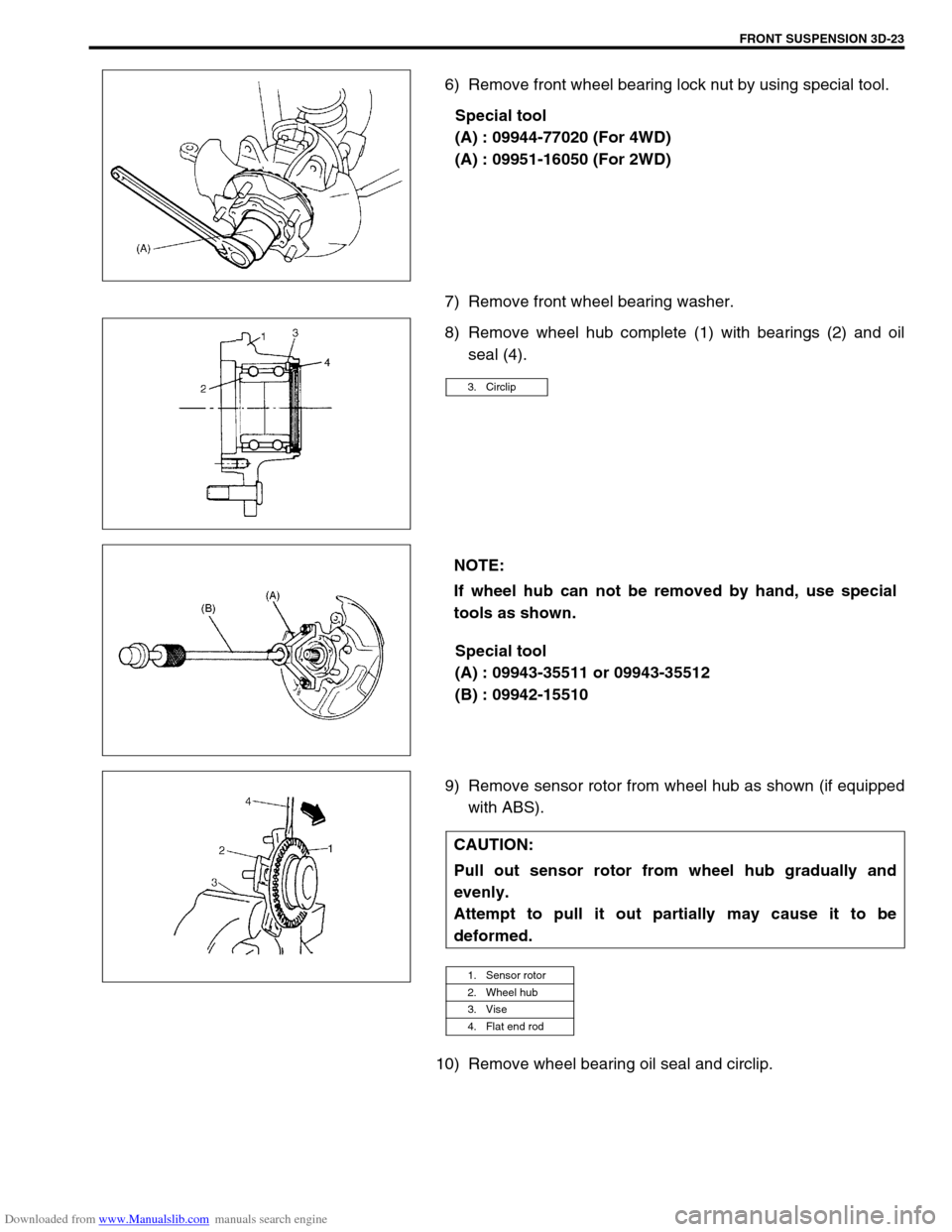
6) Remove front wheel bearing lock nut by using special tool.
Special tool
(A) : 09944-77020 (For 4WD)
(A) : 09951-16050 (For 2WD)
7) Remove front wheel bearing washer.
8) Remove wheel hub complete (1) with bearings (2) and oil
seal (4).
Special tool
(A) : 09943-35511 or 09943-35512
(B) : 09942-15510
9) Remove sensor rotor from wheel hub as shown (if equipped
with ABS).
10) Remove wheel bearing oil seal and circlip.
3. Circlip
NOTE:
If wheel hub can not be removed by hand, use special
tools as shown.
CAUTION:
Pull out sensor rotor from wheel hub gradually and
evenly.
Attempt to pull it out partially may cause it to be
deformed.
1. Sensor rotor
2. Wheel hub
3. Vise
4. Flat end rod
Page 197 of 687

Downloaded from www.Manualslib.com manuals search engine 3D-24 FRONT SUSPENSION
11) Using hydraulic press (1) and special tool remove wheel
bearing (2).
Special tool
(A) : 09913-75520
12) Remove hub bolts from hub.
INSTALLATION
1) Insert new stud in hub hole. Rotate stud slowly to assure ser-
rations are aligned with those made by original bolt.
2) Using special tool, press-fit wheel bearing (3) until its end
contacts stepped surface of wheel hub (4).
Special tool
(A) : 09944-78210
3) Install bearing circlip.
4) Drive in wheel bearing oil seal (1) by using special tools.
Special tool
(B) : 09944-66010
(C) : 09924-74510
1. Oil hydraulic press
2. Hub bolt
CAUTION:
Press-fit wheel bearing (3) vertically to hub (4).
1. Oil hydraulic press
2. Steel plate
Page 198 of 687
Downloaded from www.Manualslib.com manuals search engine FRONT SUSPENSION 3D-25
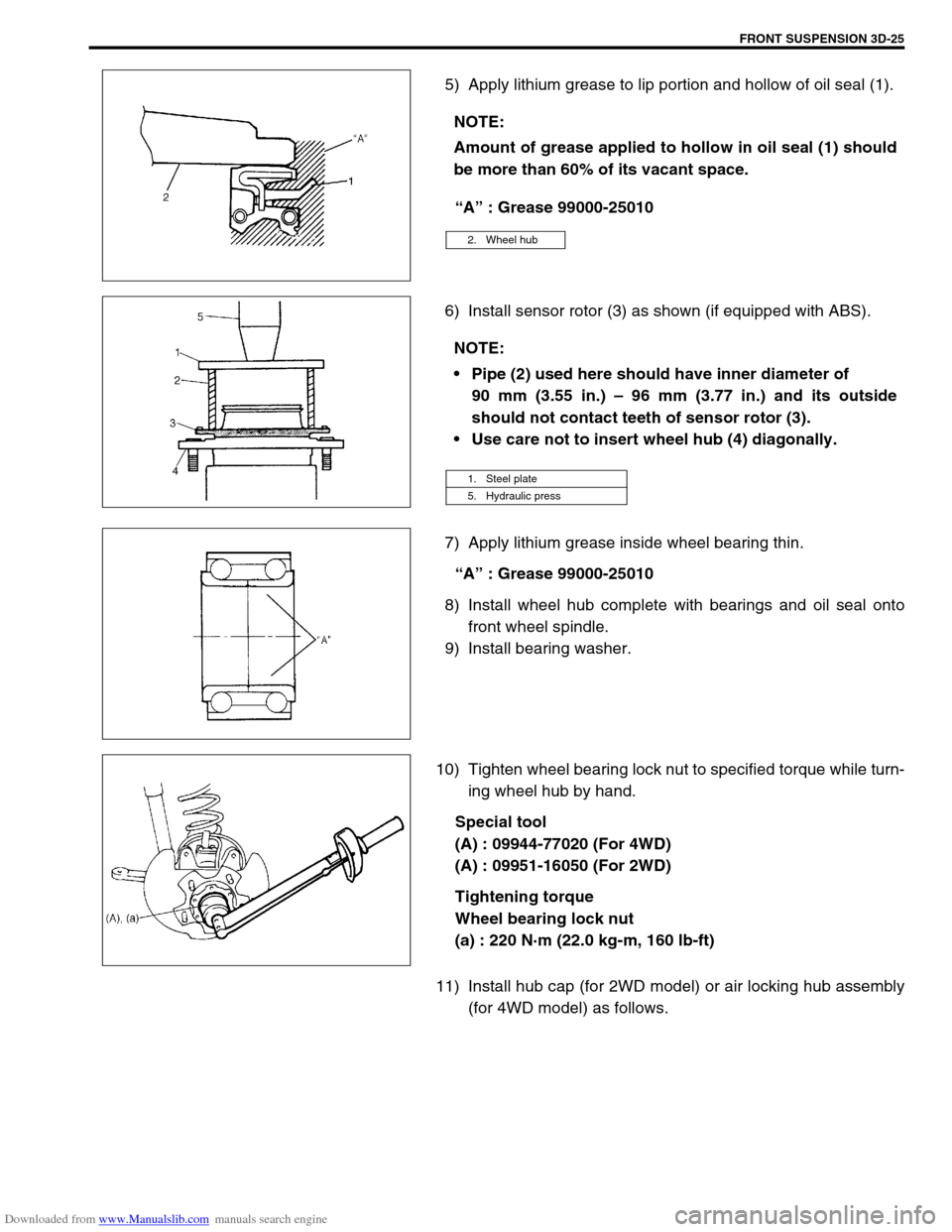
5) Apply lithium grease to lip portion and hollow of oil seal (1).
“A” : Grease 99000-25010
6) Install sensor rotor (3) as shown (if equipped with ABS).
7) Apply lithium grease inside wheel bearing thin.
“A” : Grease 99000-25010
8) Install wheel hub complete with bearings and oil seal onto
front wheel spindle.
9) Install bearing washer.
10) Tighten wheel bearing lock nut to specified torque while turn-
ing wheel hub by hand.
Special tool
(A) : 09944-77020 (For 4WD)
(A) : 09951-16050 (For 2WD)
Tightening torque
Wheel bearing lock nut
(a) : 220 N·m (22.0 kg-m, 160 lb-ft)
11) Install hub cap (for 2WD model) or air locking hub assembly
(for 4WD model) as follows. NOTE:
Amount of grease applied to hollow in oil seal (1) should
be more than 60% of its vacant space.
2. Wheel hub
NOTE:
Pipe (2) used here should have inner diameter of
90 mm (3.55 in.) – 96 mm (3.77 in.) and its outside
should not contact teeth of sensor rotor (3).
Use care not to insert wheel hub (4) diagonally.
1. Steel plate
5. Hydraulic press
Page 199 of 687
Downloaded from www.Manualslib.com manuals search engine 3D-26 FRONT SUSPENSION
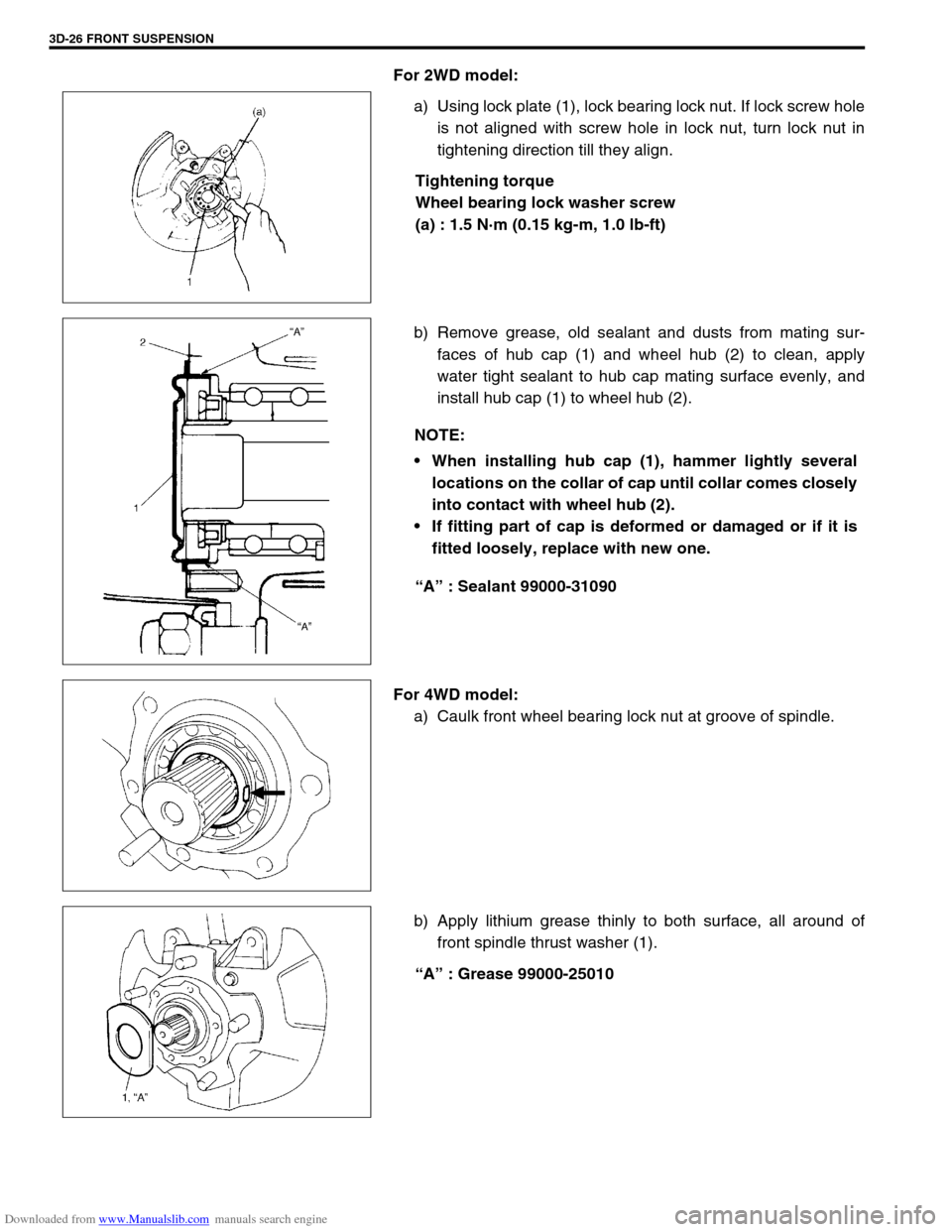
For 2WD model:
a) Using lock plate (1), lock bearing lock nut. If lock screw hole
is not aligned with screw hole in lock nut, turn lock nut in
tightening direction till they align.
Tightening torque
Wheel bearing lock washer screw
(a) : 1.5 N·m (0.15 kg-m, 1.0 lb-ft)
b) Remove grease, old sealant and dusts from mating sur-
faces of hub cap (1) and wheel hub (2) to clean, apply
water tight sealant to hub cap mating surface evenly, and
install hub cap (1) to wheel hub (2).
“A” : Sealant 99000-31090
For 4WD model:
a) Caulk front wheel bearing lock nut at groove of spindle.
b) Apply lithium grease thinly to both surface, all around of
front spindle thrust washer (1).
“A” : Grease 99000-25010
NOTE:
When installing hub cap (1), hammer lightly several
locations on the collar of cap until collar comes closely
into contact with wheel hub (2).
If fitting part of cap is deformed or damaged or if it is
fitted loosely, replace with new one.
Page 200 of 687
Downloaded from www.Manualslib.com manuals search engine FRONT SUSPENSION 3D-27
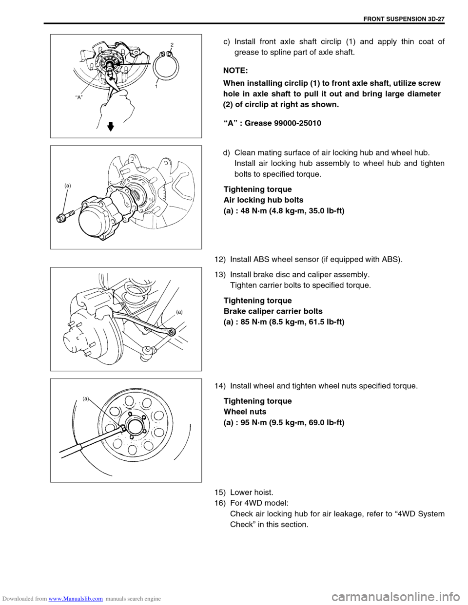
c) Install front axle shaft circlip (1) and apply thin coat of
grease to spline part of axle shaft.
“A” : Grease 99000-25010
d) Clean mating surface of air locking hub and wheel hub.
Install air locking hub assembly to wheel hub and tighten
bolts to specified torque.
Tightening torque
Air locking hub bolts
(a) : 48 N·m (4.8 kg-m, 35.0 lb-ft)
12) Install ABS wheel sensor (if equipped with ABS).
13) Install brake disc and caliper assembly.
Tighten carrier bolts to specified torque.
Tightening torque
Brake caliper carrier bolts
(a) : 85 N·m (8.5 kg-m, 61.5 lb-ft)
14) Install wheel and tighten wheel nuts specified torque.
Tightening torque
Wheel nuts
(a) : 95 N·m (9.5 kg-m, 69.0 lb-ft)
15) Lower hoist.
16) For 4WD model:
Check air locking hub for air leakage, refer to “4WD System
Check” in this section. NOTE:
When installing circlip (1) to front axle shaft, utilize screw
hole in axle shaft to pull it out and bring large diameter
(2) of circlip at right as shown.