Steering fluid SUZUKI JIMNY 2005 3.G Service Owner's Manual
[x] Cancel search | Manufacturer: SUZUKI, Model Year: 2005, Model line: JIMNY, Model: SUZUKI JIMNY 2005 3.GPages: 687, PDF Size: 13.38 MB
Page 145 of 687
Downloaded from www.Manualslib.com manuals search engine 3B1-14 POWER STEERING (P/S) SYSTEM (If equipped)
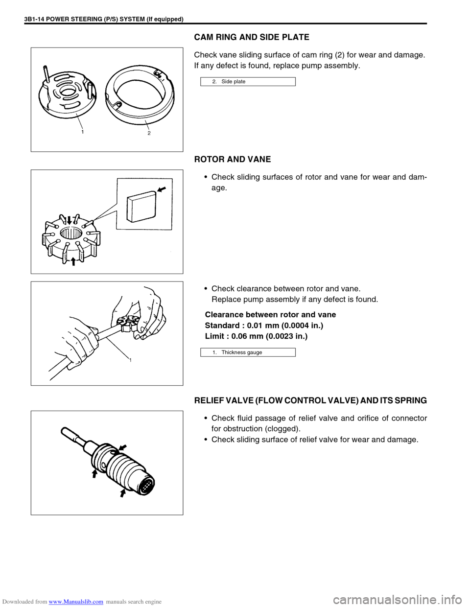
CAM RING AND SIDE PLATE
Check vane sliding surface of cam ring (2) for wear and damage.
If any defect is found, replace pump assembly.
ROTOR AND VANE
Check sliding surfaces of rotor and vane for wear and dam-
age.
Check clearance between rotor and vane.
Replace pump assembly if any defect is found.
Clearance between rotor and vane
Standard : 0.01 mm (0.0004 in.)
Limit : 0.06 mm (0.0023 in.)
RELIEF VALVE (FLOW CONTROL VALVE) AND ITS SPRING
Check fluid passage of relief valve and orifice of connector
for obstruction (clogged).
Check sliding surface of relief valve for wear and damage.
2. Side plate
1. Thickness gauge
Page 146 of 687
Downloaded from www.Manualslib.com manuals search engine POWER STEERING (P/S) SYSTEM (If equipped) 3B1-15
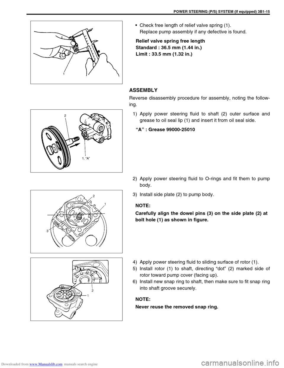
Check free length of relief valve spring (1).
Replace pump assembly if any defective is found.
Relief valve spring free length
Standard : 36.5 mm (1.44 in.)
Limit : 33.5 mm (1.32 in.)
ASSEMBLY
Reverse disassembly procedure for assembly, noting the follow-
ing.
1) Apply power steering fluid to shaft (2) outer surface and
grease to oil seal lip (1) and insert it from oil seal side.
“A” : Grease 99000-25010
2) Apply power steering fluid to O-rings and fit them to pump
body.
3) Install side plate (2) to pump body.
4) Apply power steering fluid to sliding surface of rotor (1).
5) Install rotor (1) to shaft, directing “dot” (2) marked side of
rotor toward pump cover (facing up).
6) Install new snap ring to shaft, then make sure to fit snap ring
into shaft groove securely.
NOTE:
Carefully align the dowel pins (3) on the side plate (2) at
bolt hole (1) as shown in figure.
NOTE:
Never reuse the removed snap ring.
Page 147 of 687
Downloaded from www.Manualslib.com manuals search engine 3B1-16 POWER STEERING (P/S) SYSTEM (If equipped)
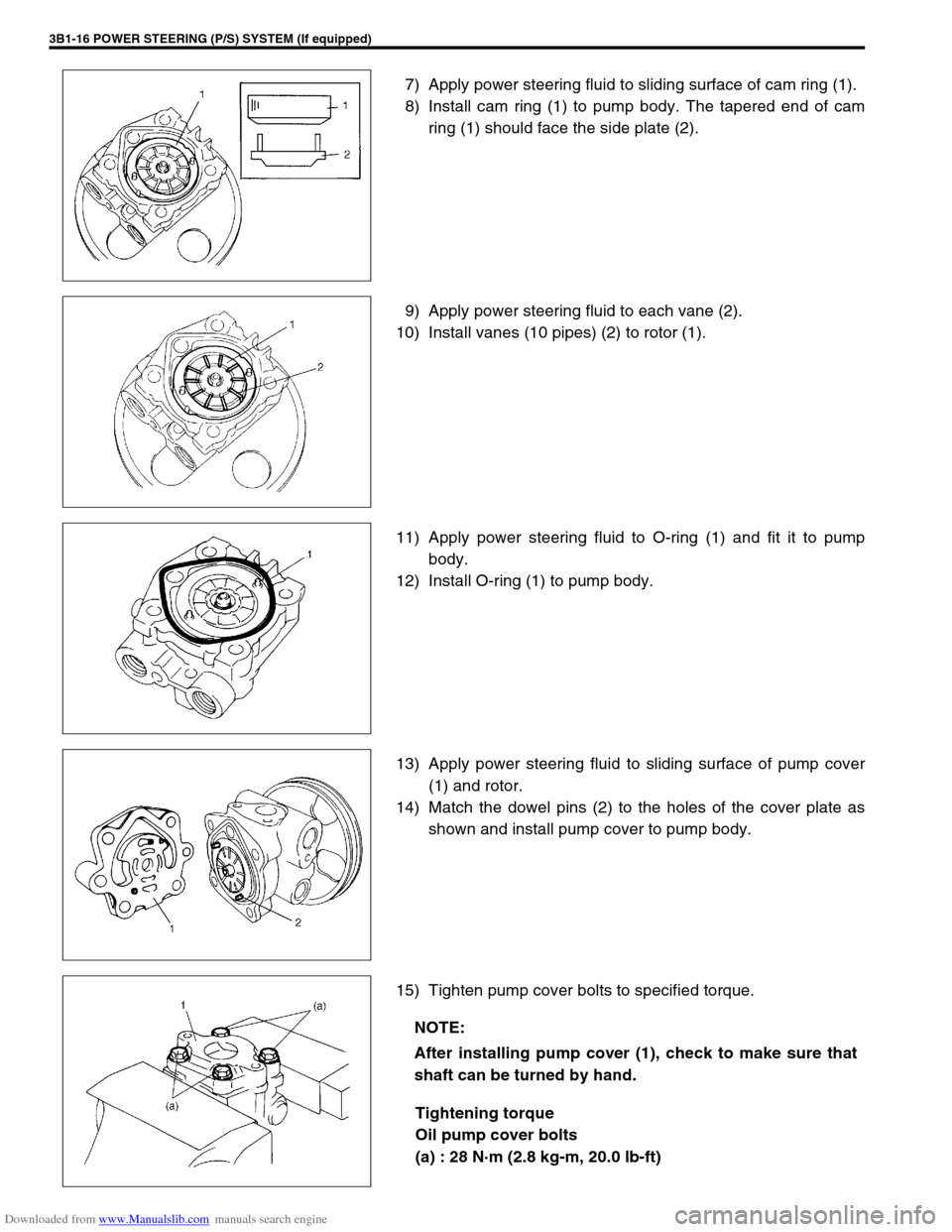
7) Apply power steering fluid to sliding surface of cam ring (1).
8) Install cam ring (1) to pump body. The tapered end of cam
ring (1) should face the side plate (2).
9) Apply power steering fluid to each vane (2).
10) Install vanes (10 pipes) (2) to rotor (1).
11) Apply power steering fluid to O-ring (1) and fit it to pump
body.
12) Install O-ring (1) to pump body.
13) Apply power steering fluid to sliding surface of pump cover
(1) and rotor.
14) Match the dowel pins (2) to the holes of the cover plate as
shown and install pump cover to pump body.
15) Tighten pump cover bolts to specified torque.
Tightening torque
Oil pump cover bolts
(a) : 28 N·m (2.8 kg-m, 20.0 lb-ft)
NOTE:
After installing pump cover (1), check to make sure that
shaft can be turned by hand.
Page 148 of 687
Downloaded from www.Manualslib.com manuals search engine POWER STEERING (P/S) SYSTEM (If equipped) 3B1-17
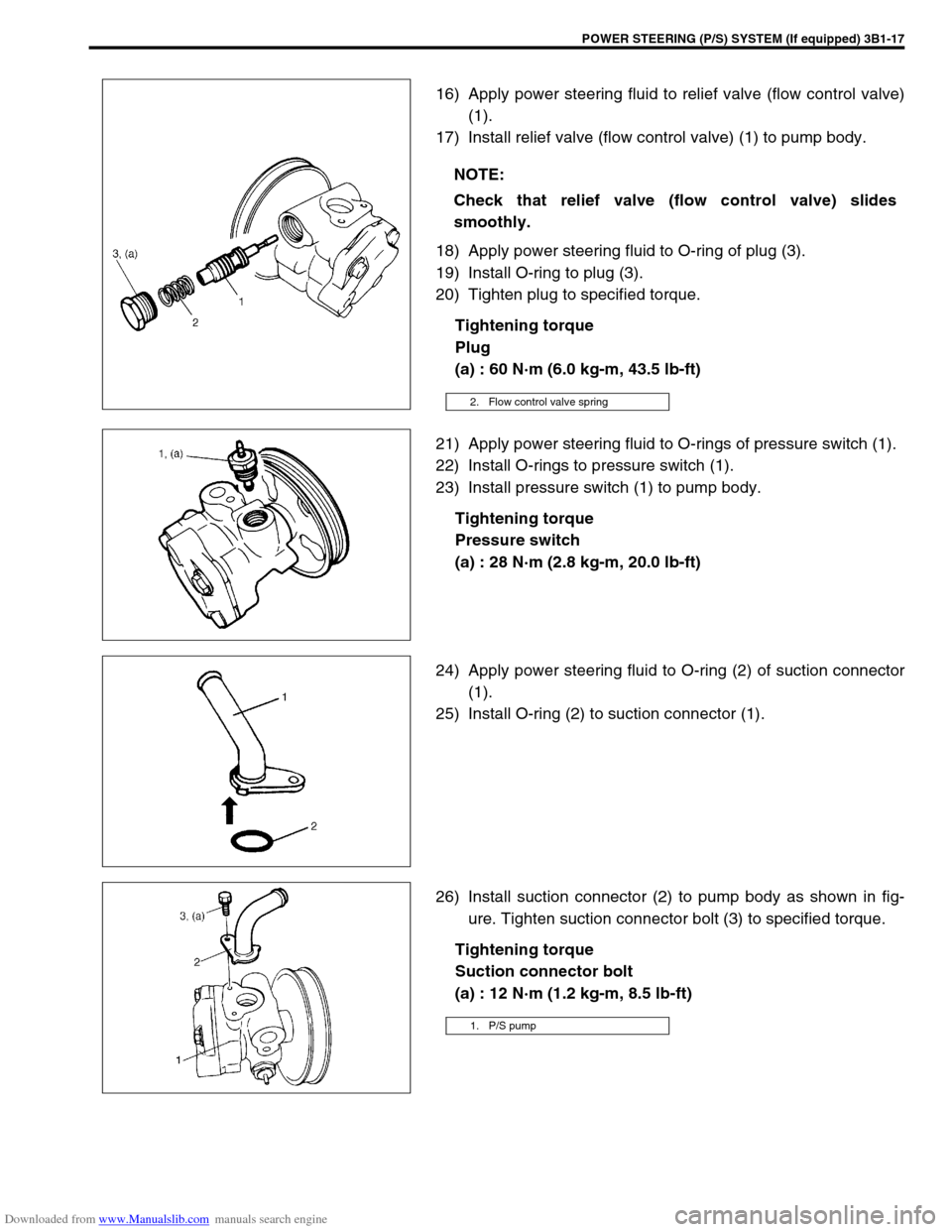
16) Apply power steering fluid to relief valve (flow control valve)
(1).
17) Install relief valve (flow control valve) (1) to pump body.
18) Apply power steering fluid to O-ring of plug (3).
19) Install O-ring to plug (3).
20) Tighten plug to specified torque.
Tightening torque
Plug
(a) : 60 N·m (6.0 kg-m, 43.5 lb-ft)
21) Apply power steering fluid to O-rings of pressure switch (1).
22) Install O-rings to pressure switch (1).
23) Install pressure switch (1) to pump body.
Tightening torque
Pressure switch
(a) : 28 N·m (2.8 kg-m, 20.0 lb-ft)
24) Apply power steering fluid to O-ring (2) of suction connector
(1).
25) Install O-ring (2) to suction connector (1).
26) Install suction connector (2) to pump body as shown in fig-
ure. Tighten suction connector bolt (3) to specified torque.
Tightening torque
Suction connector bolt
(a) : 12 N·m (1.2 kg-m, 8.5 lb-ft) NOTE:
Check that relief valve (flow control valve) slides
smoothly.
2. Flow control valve spring
1. P/S pump
Page 149 of 687
Downloaded from www.Manualslib.com manuals search engine 3B1-18 POWER STEERING (P/S) SYSTEM (If equipped)
INSTALLATION
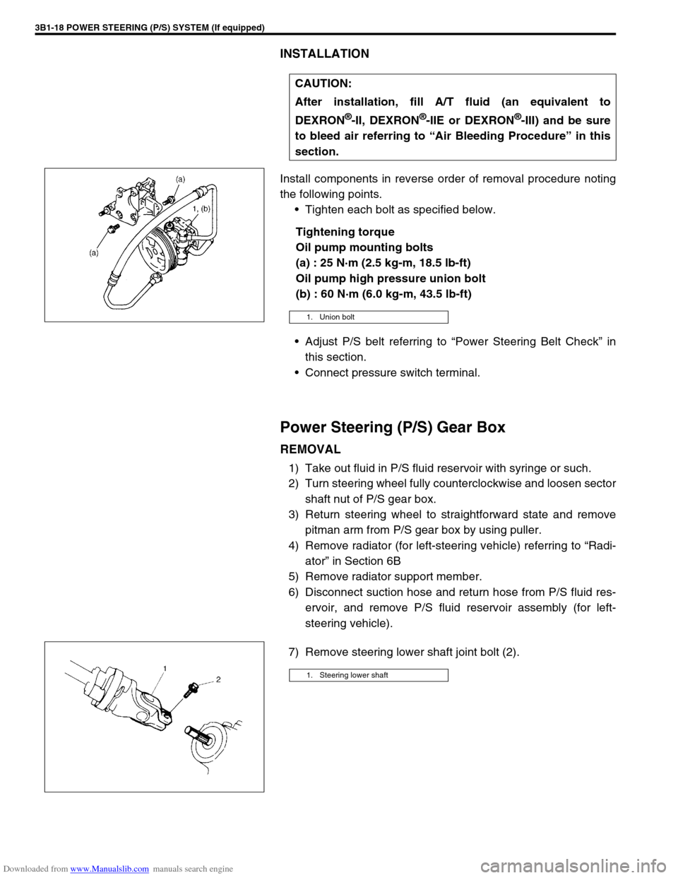
Install components in reverse order of removal procedure noting
the following points.
Tighten each bolt as specified below.
Tightening torque
Oil pump mounting bolts
(a) : 25 N·m (2.5 kg-m, 18.5 lb-ft)
Oil pump high pressure union bolt
(b) : 60 N·m (6.0 kg-m, 43.5 lb-ft)
Adjust P/S belt referring to “Power Steering Belt Check” in
this section.
Connect pressure switch terminal.
Power Steering (P/S) Gear Box
REMOVAL
1) Take out fluid in P/S fluid reservoir with syringe or such.
2) Turn steering wheel fully counterclockwise and loosen sector
shaft nut of P/S gear box.
3) Return steering wheel to straightforward state and remove
pitman arm from P/S gear box by using puller.
4) Remove radiator (for left-steering vehicle) referring to “Radi-
ator” in Section 6B
5) Remove radiator support member.
6) Disconnect suction hose and return hose from P/S fluid res-
ervoir, and remove P/S fluid reservoir assembly (for left-
steering vehicle).
7) Remove steering lower shaft joint bolt (2).CAUTION:
After installation, fill A/T fluid (an equivalent to
DEXRON
®-II, DEXRON®-IIE or DEXRON®-III) and be sure
to bleed air referring to “Air Bleeding Procedure” in this
section.
1. Union bolt
1. Steering lower shaft
Page 152 of 687
Downloaded from www.Manualslib.com manuals search engine POWER STEERING (P/S) SYSTEM (If equipped) 3B1-21
Tightening Torque Specifications
Required Service Materials
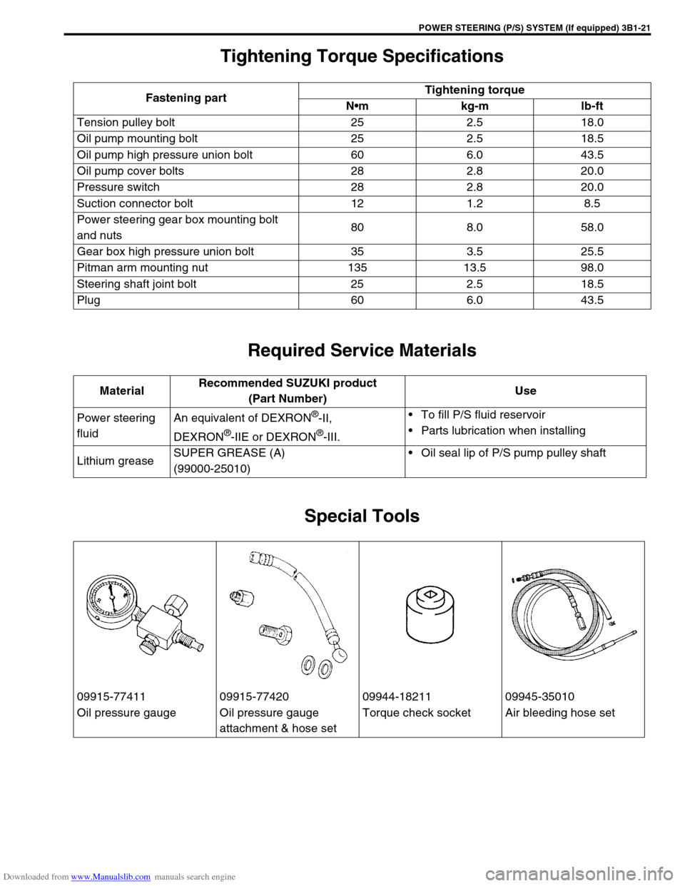
Special Tools
Fastening partTightening torque
Nm kg-m lb-ft
Tension pulley bolt 25 2.5 18.0
Oil pump mounting bolt 25 2.5 18.5
Oil pump high pressure union bolt 60 6.0 43.5
Oil pump cover bolts 28 2.8 20.0
Pressure switch 28 2.8 20.0
Suction connector bolt 12 1.2 8.5
Power steering gear box mounting bolt
and nuts80 8.0 58.0
Gear box high pressure union bolt 35 3.5 25.5
Pitman arm mounting nut 135 13.5 98.0
Steering shaft joint bolt 25 2.5 18.5
Plug 60 6.0 43.5
MaterialRecommended SUZUKI product
(Part Number)Use
Power steering
fluidAn equivalent of DEXRON
®-II,
DEXRON
®-IIE or DEXRON®-III.To fill P/S fluid reservoir
Parts lubrication when installing
Lithium greaseSUPER GREASE (A)
(99000-25010)Oil seal lip of P/S pump pulley shaft
09915-77411 09915-77420 09944-18211 09945-35010
Oil pressure gauge Oil pressure gauge
attachment & hose setTorque check socket Air bleeding hose set
Page 267 of 687

Downloaded from www.Manualslib.com manuals search engine 5-6 BRAKES
Excessive pedal travel
(Pedal stroke too
large)Partial brake system failure Check brake systems and repair as
necessary.
Insufficient fluid in master cylinder reservoirs Fill reservoirs with approved brake
fluid.
Check for leaks and air in brake
systems.
Check warning light. Bleed system
if required.
Air in system (pedal soft/spongy) Bleed system.
Rear brake system not adjusted (malfunctioning
auto adjusting mechanism)Repair auto adjusting mechanism.
Adjust rear brakes.
Bent brake shoes Replace brake shoes.
Worn rear brake shoes Replace brake shoes.
Dragging brakes (A
very light drag is
present in all disc
brakes immediately
after pedal is released)Master cylinder pistons not returning correctly Repair master cylinder.
Restricted brake tubes or hoses Check for soft hoses or damaged
tubes and replace with new hoses
and/or new brake tubes.
Incorrect parking brake adjustment on rear
brakesCheck and adjust to correct specifi-
cations.
Weakened or broken return springs in the brake Replace.
Sluggish parking-brake cables or linkage Repair or replace.
Wheel cylinder or caliper piston sticking Repair as necessary.
Malfunctioning ABS, if equipped with ABS Check system and replace as nec-
essary.
Pedal pulsation (Pedal
pulsates when
depressed for brak-
ing.) Damaged or loose wheel bearings Replace wheel bearings.
Distorted steering knuckle or rear axle shafts Replace knuckle or rear axle shaft.
Excessive disc lateral runout Check per instructions. If not within
specifications, replace or machine
the disc.
Parallelism not within specifications Check per instructions. If not with
specifications, replace or machine
the disc.
Rear drums out of round. Check runout.
Repair or replace drum as neces-
sary.
Braking noise
Glazed shoe linings, or foreign matters stuck to
liningsRepair or replace brake shoe.
Worn or distorted shoe linings Replace brake shoe (or pad).
Loose front wheel bearings Replace wheel bearing.
Distorted backing plates or loose mounting
boltsReplace or retighten securing bolts.
Brake warning light
turns on after engine
startParking brake applied Release parking brake and check
that brake warning light turns off.
Insufficient amount of brake fluid Add brake fluid.
Brake fluid leaking from brake line Investigate leaky point, correct it
and add brake fluid.
Brake warning light circuit faulty Repair circuit. Condition Possible Cause Correction
Page 311 of 687

Downloaded from www.Manualslib.com manuals search engine 5-50 BRAKES
REMOVAL
1) Raise, suitably support vehicle. Remove wheel if necessary.
2) Clean dirt and foreign material from both hose end or pipe end fittings. Remove brake hose and pipe.
INSTALLATION
1) Install brake hose and pipe by reversing removal procedure, noting the following points.
For installation, make sure that steering wheel is in straightforward position and hose has no twist or kink.
Check to make sure that hose doesn’t contact any part of suspension, both in extreme right and extreme left
turn conditions. If it does at any point, remove and correct. Fill and maintain brake fluid level in reservoir.
Bleed brake system.
2) Perform brake test and check installed part for fluid leakage.
Page 319 of 687
Downloaded from www.Manualslib.com manuals search engine 5E-2 ANTILOCK BRAKE SYSTEM (ABS)
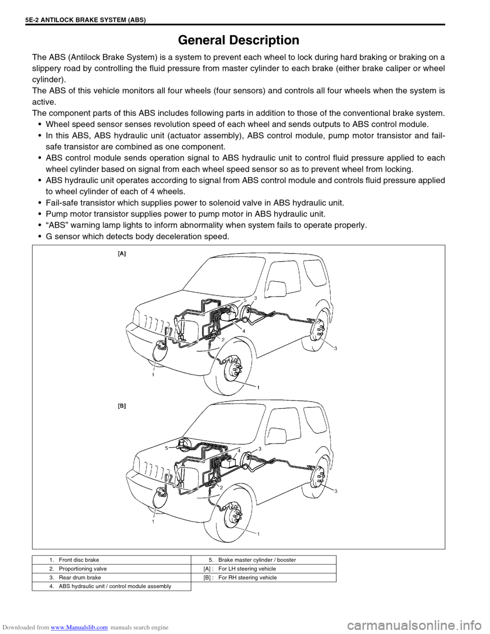
General Description
The ABS (Antilock Brake System) is a system to prevent each wheel to lock during hard braking or braking on a
slippery road by controlling the fluid pressure from master cylinder to each brake (either brake caliper or wheel
cylinder).
The ABS of this vehicle monitors all four wheels (four sensors) and controls all four wheels when the system is
active.
The component parts of this ABS includes following parts in addition to those of the conventional brake system.
Wheel speed sensor senses revolution speed of each wheel and sends outputs to ABS control module.
In this ABS, ABS hydraulic unit (actuator assembly), ABS control module, pump motor transistor and fail-
safe transistor are combined as one component.
ABS control module sends operation signal to ABS hydraulic unit to control fluid pressure applied to each
wheel cylinder based on signal from each wheel speed sensor so as to prevent wheel from locking.
ABS hydraulic unit operates according to signal from ABS control module and controls fluid pressure applied
to wheel cylinder of each of 4 wheels.
Fail-safe transistor which supplies power to solenoid valve in ABS hydraulic unit.
Pump motor transistor supplies power to pump motor in ABS hydraulic unit.
“ABS” warning lamp lights to inform abnormality when system fails to operate properly.
G sensor which detects body deceleration speed.
1. Front disc brake 5. Brake master cylinder / booster
2. Proportioning valve [A] : For LH steering vehicle
3. Rear drum brake [B] : For RH steering vehicle
4. ABS hydraulic unit / control module assembly
Page 510 of 687
Downloaded from www.Manualslib.com manuals search engine ENGINE MECHANICAL (M13 ENGINE) 6A1-29
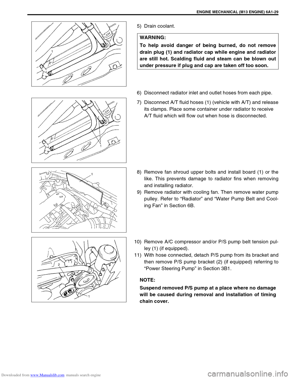
5) Drain coolant.
6) Disconnect radiator inlet and outlet hoses from each pipe.
7) Disconnect A/T fluid hoses (1) (vehicle with A/T) and release
its clamps. Place some container under radiator to receive
A/T fluid which will flow out when hose is disconnected.
8) Remove fan shroud upper bolts and install board (1) or the
like. This prevents damage to radiator fins when removing
and installing radiator.
9) Remove radiator with cooling fan. Then remove water pump
pulley. Refer to “Radiator” and “Water Pump Belt and Cool-
ing Fan” in Section 6B.
10) Remove A/C compressor and/or P/S pump belt tension pul-
ley (1) (if equipped).
11) With hose connected, detach P/S pump from its bracket and
then remove P/S pump bracket (2) (if equipped) referring to
“Power Steering Pump” in Section 3B1. WARNING:
To help avoid danger of being burned, do not remove
drain plug (1) and radiator cap while engine and radiator
are still hot. Scalding fluid and steam can be blown out
under pressure if plug and cap are taken off too soon.
NOTE:
Suspend removed P/S pump at a place where no damage
will be caused during removal and installation of timing
chain cover.