check engine SUZUKI JIMNY 2005 3.G Service Owner's Manual
[x] Cancel search | Manufacturer: SUZUKI, Model Year: 2005, Model line: JIMNY, Model: SUZUKI JIMNY 2005 3.GPages: 687, PDF Size: 13.38 MB
Page 44 of 687
Downloaded from www.Manualslib.com manuals search engine MAINTENANCE AND LUBRICATION 0B-13
Parking Brake Lever and Cable
INSPECTION
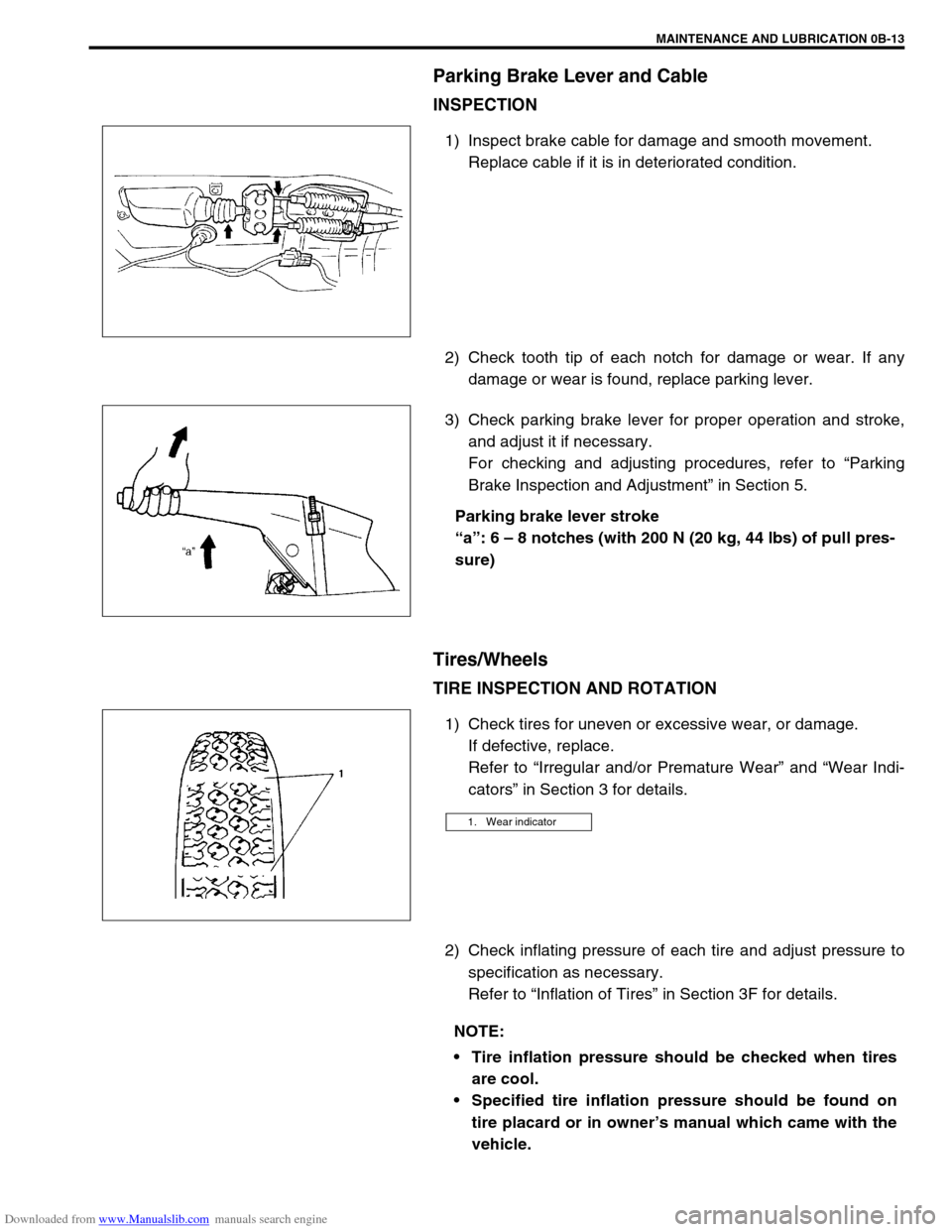
1) Inspect brake cable for damage and smooth movement.
Replace cable if it is in deteriorated condition.
2) Check tooth tip of each notch for damage or wear. If any
damage or wear is found, replace parking lever.
3) Check parking brake lever for proper operation and stroke,
and adjust it if necessary.
For checking and adjusting procedures, refer to “Parking
Brake Inspection and Adjustment” in Section 5.
Parking brake lever stroke
“a”: 6 – 8 notches (with 200 N (20 kg, 44 lbs) of pull pres-
sure)
Tires/Wheels
TIRE INSPECTION AND ROTATION
1) Check tires for uneven or excessive wear, or damage.
If defective, replace.
Refer to “Irregular and/or Premature Wear” and “Wear Indi-
cators” in Section 3 for details.
2) Check inflating pressure of each tire and adjust pressure to
specification as necessary.
Refer to “Inflation of Tires” in Section 3F for details.
1. Wear indicator
NOTE:
Tire inflation pressure should be checked when tires
are cool.
Specified tire inflation pressure should be found on
tire placard or in owner’s manual which came with the
vehicle.
Page 45 of 687
Downloaded from www.Manualslib.com manuals search engine 0B-14 MAINTENANCE AND LUBRICATION
3) Rotate tires.
For details, refer to “Tire Rotation” in Section 3F.
WHEEL DISCS INSPECTION
Inspect each wheel disc for dents, distortion and cracks. A disc in
badly damaged condition must be replaced.
WHEEL BEARING INSPECTION
1) Check front wheel bearing for wear, damage, abnormal
noise or rattles. For details, refer to “Wheel Disc, Nut and
Bearing Check” in Section 3D.
2) Check rear wheel bearing for wear, damage, abnormal noise
or rattles. For details, refer to “Wheel Disc, Nut and Bearing
Check” in Section 3E.
Suspension System
INSPECTION
Check suspension bolts and nuts for tightness and retighten them
as necessary.
Repair or replace defective parts, if any.
FRONT
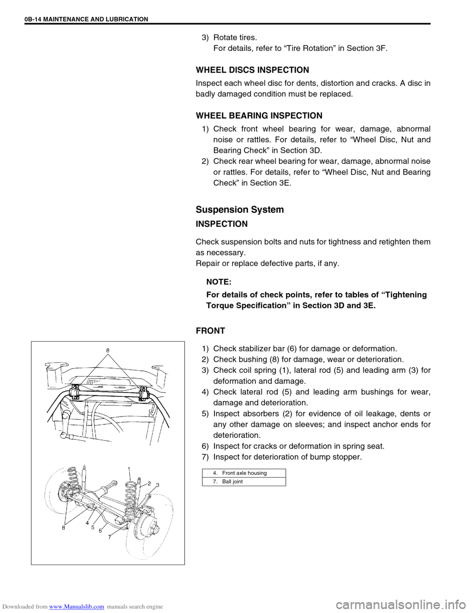
1) Check stabilizer bar (6) for damage or deformation.
2) Check bushing (8) for damage, wear or deterioration.
3) Check coil spring (1), lateral rod (5) and leading arm (3) for
deformation and damage.
4) Check lateral rod (5) and leading arm bushings for wear,
damage and deterioration.
5) Inspect absorbers (2) for evidence of oil leakage, dents or
any other damage on sleeves; and inspect anchor ends for
deterioration.
6) Inspect for cracks or deformation in spring seat.
7) Inspect for deterioration of bump stopper.NOTE:
For details of check points, refer to tables of “Tightening
Torque Specification” in Section 3D and 3E.
4. Front axle housing
7. Ball joint
Page 46 of 687
Downloaded from www.Manualslib.com manuals search engine MAINTENANCE AND LUBRICATION 0B-15
REAR
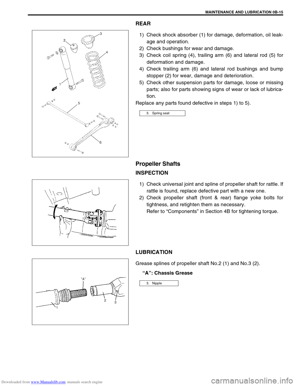
1) Check shock absorber (1) for damage, deformation, oil leak-
age and operation.
2) Check bushings for wear and damage.
3) Check coil spring (4), trailing arm (6) and lateral rod (5) for
deformation and damage.
4) Check trailing arm (6) and lateral rod bushings and bump
stopper (2) for wear, damage and deterioration.
5) Check other suspension parts for damage, loose or missing
parts; also for parts showing signs of wear or lack of lubrica-
tion.
Replace any parts found defective in steps 1) to 5).
Propeller Shafts
INSPECTION
1) Check universal joint and spline of propeller shaft for rattle. If
rattle is found, replace defective part with a new one.
2) Check propeller shaft (front & rear) flange yoke bolts for
tightness, and retighten them as necessary.
Refer to “Components” in Section 4B for tightening torque.
LUBRICATION
Grease splines of propeller shaft No.2 (1) and No.3 (2).
“A”: Chassis Grease
3. Spring seat
3. Nipple
Page 47 of 687
Downloaded from www.Manualslib.com manuals search engine 0B-16 MAINTENANCE AND LUBRICATION
Manual Transmission Oil
INSPECTION
1) Inspect transmission case for evidence of oil leakage.
Repair leaky point if any.
2) Make sure that vehicle is placed level for oil level check.
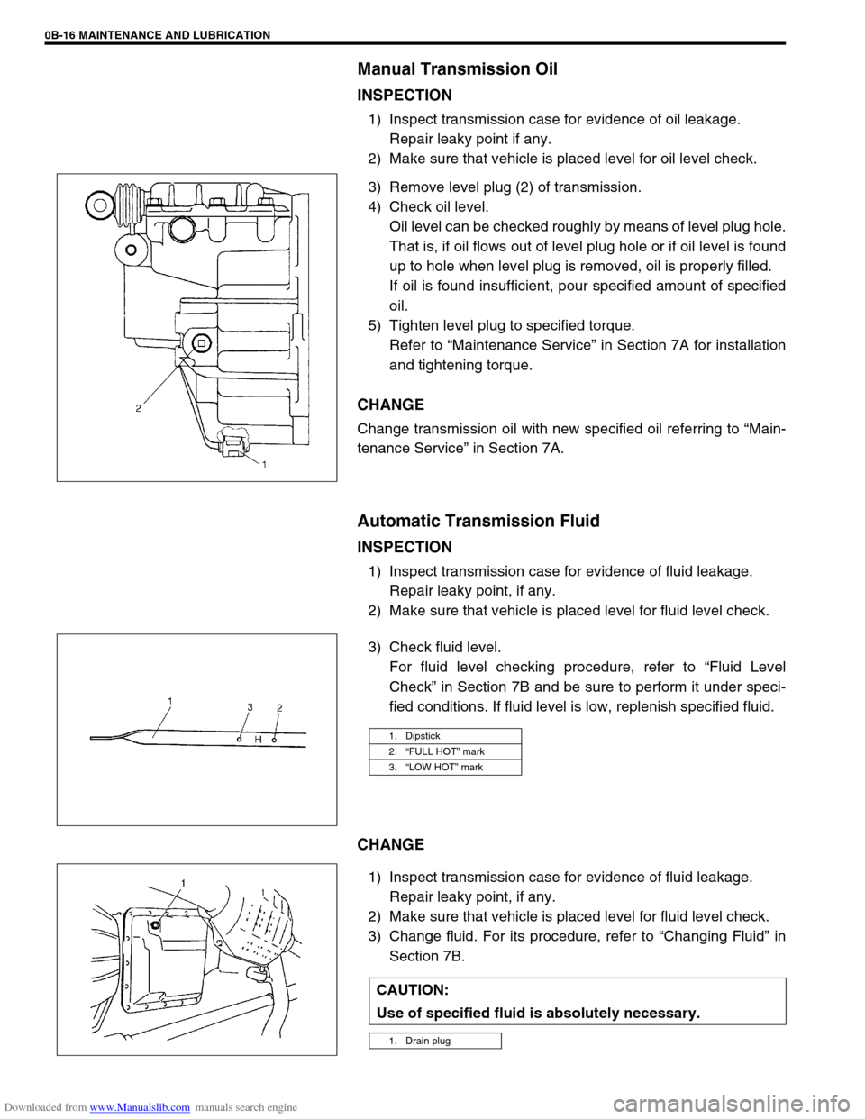
3) Remove level plug (2) of transmission.
4) Check oil level.
Oil level can be checked roughly by means of level plug hole.
That is, if oil flows out of level plug hole or if oil level is found
up to hole when level plug is removed, oil is properly filled.
If oil is found insufficient, pour specified amount of specified
oil.
5) Tighten level plug to specified torque.
Refer to “Maintenance Service” in Section 7A for installation
and tightening torque.
CHANGE
Change transmission oil with new specified oil referring to “Main-
tenance Service” in Section 7A.
Automatic Transmission Fluid
INSPECTION
1) Inspect transmission case for evidence of fluid leakage.
Repair leaky point, if any.
2) Make sure that vehicle is placed level for fluid level check.
3) Check fluid level.
For fluid level checking procedure, refer to “Fluid Level
Check” in Section 7B and be sure to perform it under speci-
fied conditions. If fluid level is low, replenish specified fluid.
CHANGE
1) Inspect transmission case for evidence of fluid leakage.
Repair leaky point, if any.
2) Make sure that vehicle is placed level for fluid level check.
3) Change fluid. For its procedure, refer to “Changing Fluid” in
Section 7B.
1. Dipstick
2.“FULL HOT” mark
3.“LOW HOT” mark
CAUTION:
Use of specified fluid is absolutely necessary.
1. Drain plug
Page 48 of 687
Downloaded from www.Manualslib.com manuals search engine MAINTENANCE AND LUBRICATION 0B-17
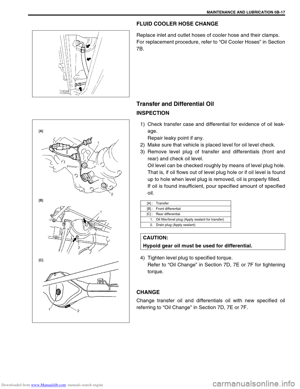
FLUID COOLER HOSE CHANGE
Replace inlet and outlet hoses of cooler hose and their clamps.
For replacement procedure, refer to “Oil Cooler Hoses” in Section
7B.
Transfer and Differential Oil
INSPECTION
1) Check transfer case and differential for evidence of oil leak-
age.
Repair leaky point if any.
2) Make sure that vehicle is placed level for oil level check.
3) Remove level plug of transfer and differentials (front and
rear) and check oil level.
Oil level can be checked roughly by means of level plug hole.
That is, if oil flows out of level plug hole or if oil level is found
up to hole when level plug is removed, oil is properly filled.
If oil is found insufficient, pour specified amount of specified
oil.
4) Tighten level plug to specified torque.
Refer to “Oil Change” in Section 7D, 7E or 7F for tightening
torque.
CHANGE
Change transfer oil and differentials oil with new specified oil
referring to “Oil Change” in Section 7D, 7E or 7F.
[A] : Transfer
[B] : Front differential
[C] : Rear differential
1. Oil filler/level plug (Apply sealant for transfer)
2. Drain plug (Apply sealant)
CAUTION:
Hypoid gear oil must be used for differential.
Page 49 of 687
Downloaded from www.Manualslib.com manuals search engine 0B-18 MAINTENANCE AND LUBRICATION
Steering System
INSPECTION
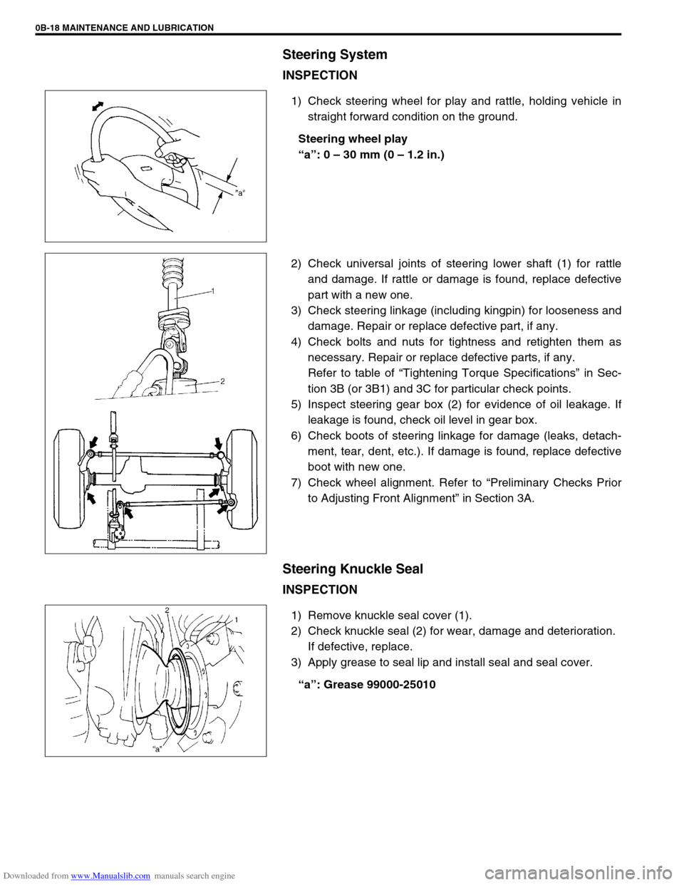
1) Check steering wheel for play and rattle, holding vehicle in
straight forward condition on the ground.
Steering wheel play
“a”: 0 – 30 mm (0 – 1.2 in.)
2) Check universal joints of steering lower shaft (1) for rattle
and damage. If rattle or damage is found, replace defective
part with a new one.
3) Check steering linkage (including kingpin) for looseness and
damage. Repair or replace defective part, if any.
4) Check bolts and nuts for tightness and retighten them as
necessary. Repair or replace defective parts, if any.
Refer to table of “Tightening Torque Specifications” in Sec-
tion 3B (or 3B1) and 3C for particular check points.
5) Inspect steering gear box (2) for evidence of oil leakage. If
leakage is found, check oil level in gear box.
6) Check boots of steering linkage for damage (leaks, detach-
ment, tear, dent, etc.). If damage is found, replace defective
boot with new one.
7) Check wheel alignment. Refer to “Preliminary Checks Prior
to Adjusting Front Alignment” in Section 3A.
Steering Knuckle Seal
INSPECTION
1) Remove knuckle seal cover (1).
2) Check knuckle seal (2) for wear, damage and deterioration.
If defective, replace.
3) Apply grease to seal lip and install seal and seal cover.
“a”: Grease 99000-25010
Page 50 of 687
Downloaded from www.Manualslib.com manuals search engine MAINTENANCE AND LUBRICATION 0B-19
Power Steering (P/S) System (if equipped)
INSPECTION
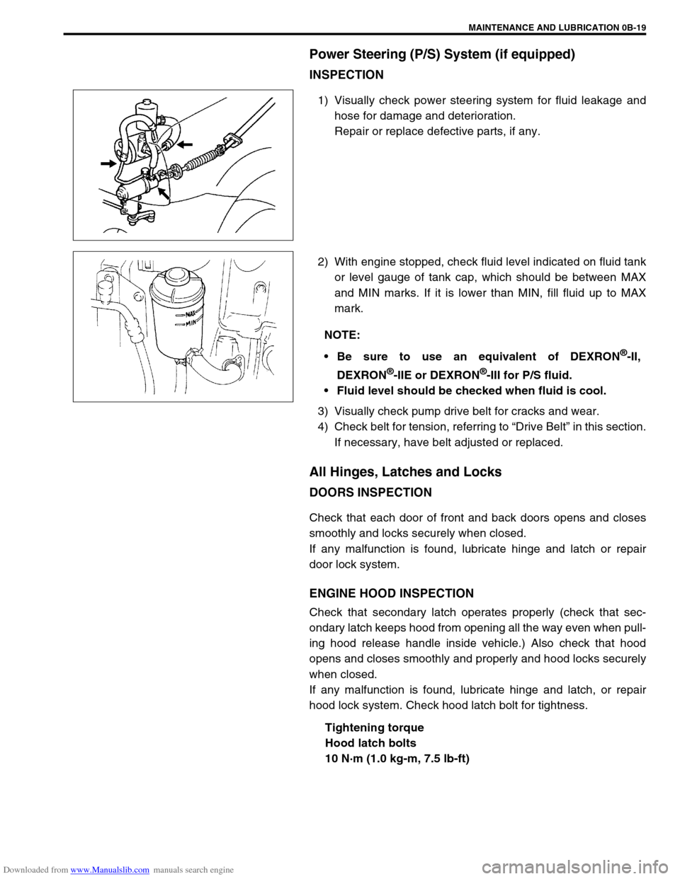
1) Visually check power steering system for fluid leakage and
hose for damage and deterioration.
Repair or replace defective parts, if any.
2) With engine stopped, check fluid level indicated on fluid tank
or level gauge of tank cap, which should be between MAX
and MIN marks. If it is lower than MIN, fill fluid up to MAX
mark.
3) Visually check pump drive belt for cracks and wear.
4) Check belt for tension, referring to “Drive Belt” in this section.
If necessary, have belt adjusted or replaced.
All Hinges, Latches and Locks
DOORS INSPECTION
Check that each door of front and back doors opens and closes
smoothly and locks securely when closed.
If any malfunction is found, lubricate hinge and latch or repair
door lock system.
ENGINE HOOD INSPECTION
Check that secondary latch operates properly (check that sec-
ondary latch keeps hood from opening all the way even when pull-
ing hood release handle inside vehicle.) Also check that hood
opens and closes smoothly and properly and hood locks securely
when closed.
If any malfunction is found, lubricate hinge and latch, or repair
hood lock system. Check hood latch bolt for tightness.
Tightening torque
Hood latch bolts
10 N·m (1.0 kg-m, 7.5 lb-ft)
NOTE:
Be sure to use an equivalent of DEXRON
®-II,
DEXRON
®-IIE or DEXRON®-III for P/S fluid.
Fluid level should be checked when fluid is cool.
Page 51 of 687

Downloaded from www.Manualslib.com manuals search engine 0B-20 MAINTENANCE AND LUBRICATION
Final Inspection
SEATS
Check that seat slides smoothly and locks securely at any position. Also check that reclining mechanism of front
seat back allows it to be locked at any angle.
SEAT BELT
Inspect belt system including webbing, buckles, latch plates, retractors and anchors for damage or wear.
If “REPLACE BELT” label on front seat belt is visible, replace belt. Check that seat belt is securely locked.
BATTERY ELECTROLYTE LEVEL CHECK
Check that the electrolyte level of all battery cells is between the upper and lower level lines on the case. If bat-
tery is equipped with built-in indicator, check battery condition by the indicator.
ACCELERATOR PEDAL OPERATION
Check that pedal operates smoothly without getting caught or interfered by any other part.
ENGINE START
Check engine start for readiness.
On automatic transmission vehicles, try to start the engine in each select lever position. The starting motor
should crank only in “P” (Park) or “N” (Neutral).
On manual transmission vehicles, place the shift lever in “Neutral,” depress clutch pedal fully any try to start.
EXHAUST SYSTEM CHECK
Check for leakage, cracks or loose supports.
CLUTCH (FOR MANUAL TRANSMISSION)
Check for the following.
Clutch is completely released when depressing clutch pedal,
No slipping clutch occurs when releasing pedal and accelerating.
Clutch itself is free from any abnormal condition. WARNING:
When carrying out road tests, select a safe place where no man or no running vehicle is seen so as to
prevent any accident.
WARNING:
Before performing the following check, be sure to have enough room around the vehicle. Then, firmly
apply both the parking brake and the regular brakes. Do not use the accelerator pedal. If the engine
starts, be ready to turn off the ignition promptly. Take these precautions because the vehicle could
move without warning and possibly cause personal injury or property damage.
Page 52 of 687

Downloaded from www.Manualslib.com manuals search engine MAINTENANCE AND LUBRICATION 0B-21
GEARSHIFT OR SELECTOR LEVER (TRANSMISSION)
Check gear shift or selector lever for smooth shifting to all positions and for good performance of transmission in
any position.
With automatic transmission equipped vehicle, also check that shift indicator indicates properly according to
which position selector lever is shifted to.
With automatic transmission equipped vehicle, make sure that vehicle is at complete stop when shifting selector
lever to “P” range position and release all brakes.
BRAKE
Foot Brake
Check the following:
that brake pedal has proper travel,
that brake works properly,
that it is free from noise,
that braking force is applied equally on all wheels,
and that brake do not drag.
Parking Brake
Check that lever has proper travel.
Check to ensure that parking brake is fully effective when the vehicle is stopped on the safe slope and brake
lever is pulled all the way.
STEERING
Check to ensure that steering wheel is free from instability, or abnormally heavy feeling.
Check that the vehicle does not wander or pull to one side.
ENGINE
Check that engine responds readily at all speeds.
Check that engine is free from abnormal noise and abnormal vibration.
BODY, WHEELS AND POWER TRANSMITTING SYSTEM
Check that body, wheels and power transmitting system are free from abnormal noise and abnormal vibration or
any other abnormal condition.
METERS AND GAUGE
Check that speedometer, odometer, fuel meter, temperature gauge, etc. are operating accurately.
LIGHTS
Check that all lights operate properly.
WINDSHIELD DEFROSTER
Periodically check that air comes out from defroster outlet when operating heater or air conditioning.
Set mode control lever to defroster position and fan switch lever to “HI” position for this check. WARNING:
With vehicle parked on a fairly steep slope, make sure nothing is in the way downhill to avoid any per-
sonal injury or property damage. Be prepared to apply regular brake quickly even if vehicle should
start to move.
Page 56 of 687
Downloaded from www.Manualslib.com manuals search engine HEATER AND VENTILATION 1A-3
Diagnosis
Diagnosis Table
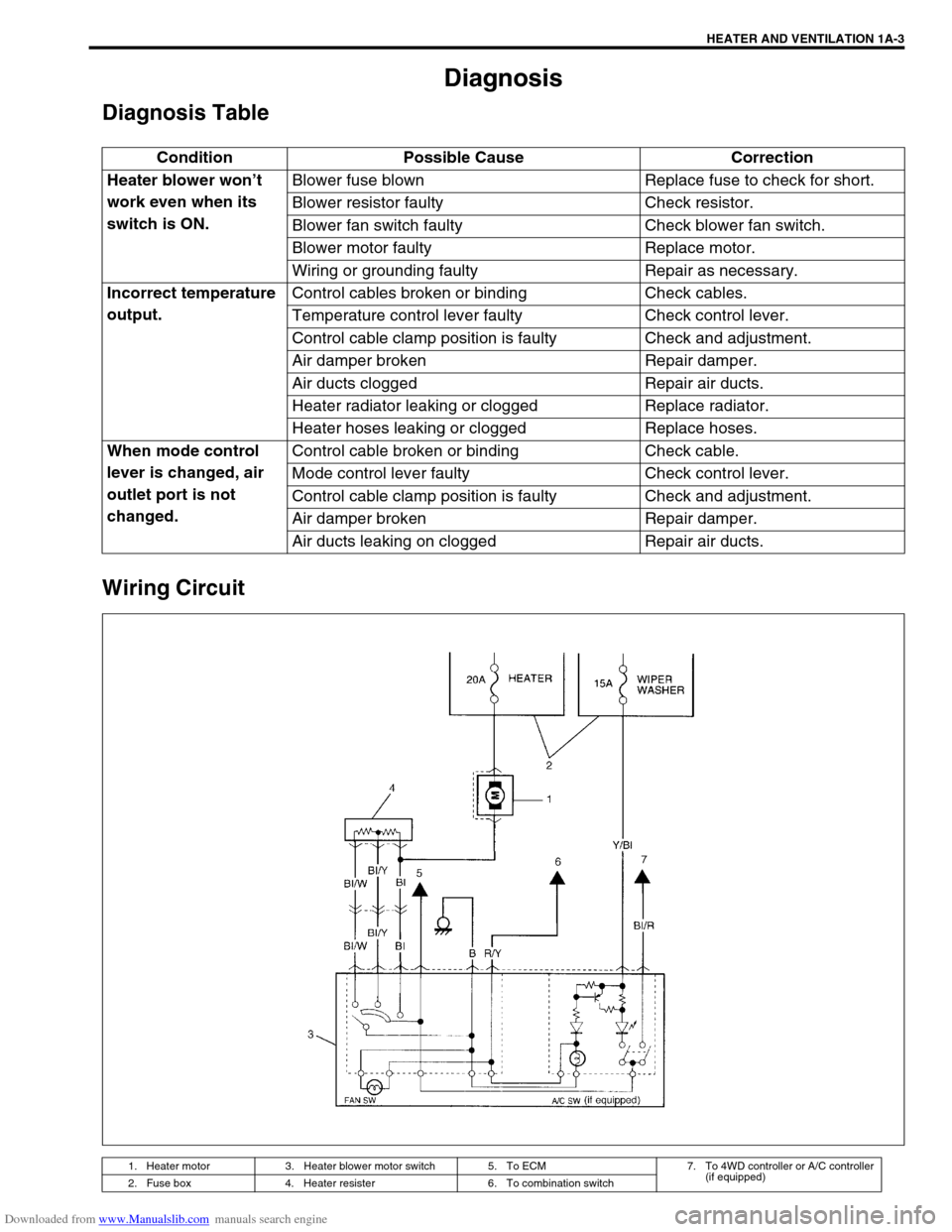
Wiring Circuit
Condition Possible Cause Correction
Heater blower won’t
work even when its
switch is ON.Blower fuse blown Replace fuse to check for short.
Blower resistor faulty Check resistor.
Blower fan switch faulty Check blower fan switch.
Blower motor faulty Replace motor.
Wiring or grounding faulty Repair as necessary.
Incorrect temperature
output.Control cables broken or binding Check cables.
Temperature control lever faulty Check control lever.
Control cable clamp position is faulty Check and adjustment.
Air damper broken Repair damper.
Air ducts clogged Repair air ducts.
Heater radiator leaking or clogged Replace radiator.
Heater hoses leaking or clogged Replace hoses.
When mode control
lever is changed, air
outlet port is not
changed.Control cable broken or binding Check cable.
Mode control lever faulty Check control lever.
Control cable clamp position is faulty Check and adjustment.
Air damper broken Repair damper.
Air ducts leaking on clogged Repair air ducts.
1. Heater motor 3. Heater blower motor switch 5. To ECM 7. To 4WD controller or A/C controller
(if equipped)
2. Fuse box 4. Heater resister 6. To combination switch