check engine SUZUKI JIMNY 2005 3.G Service Service Manual
[x] Cancel search | Manufacturer: SUZUKI, Model Year: 2005, Model line: JIMNY, Model: SUZUKI JIMNY 2005 3.GPages: 687, PDF Size: 13.38 MB
Page 74 of 687

Downloaded from www.Manualslib.com manuals search engine AIR CONDITIONING (OPTIONAL) 1B-13
CROSSING POINT OF CENTER VENTILATION LOUVER TEMPERATURE AND RECIRCULATION AIR
INLET TEMPERATURE
Detail diagnosis table (Ambient temperature at 30°C (86°F))
Condition Possible Cause Correction
Crossing point is
higher than accept-
able range
(“E” area)Insufficient or excessive charge of refrigerant Check refrigerant pressure
Dirty or bent A/C evaporator fins Clean or repair
Air leakage from cooling (heater) unit or air duct Repair or replace
Malfunctioning, switch over function of door in
cooling (heater) unitRepair or replace
Compressor malfunction Check compressor
Crossing point is
lower than acceptable
range
(“F” area)Insufficient air volume from center duct (Heater
blower malfunction)Check blower motor and fan
Compressor malfunction Check compressor
Condition
Possible Cause Correction MANIFOLD
GAUGEMPa
(kg/cm
2)
(psi)Detail
Lo Hi
0.23 – 0.35
(2.3 – 3.5)
(33 – 50)1.4 – 1.75
(14 – 17.5)
(200 – 249)Normal condition
––
Negative
pressure0.5 – 0.6
(5 – 6)
(71.2 – 85.3)The low pressure side
reads a negative pres-
sure, and the high pres-
sure side reads an
extremely low pressure.
Presence of frost
around tubing to and
from receiver / dryer
and expansion valve.Dust particles or water
droplets are either stuck
or frozen inside expan-
sion valve, preventing the
refrigerant from flowing.Clean expansion valve.
Replace it if it cannot be
cleaned.
Replace receiver / dryer.
Evacuate the A/C sys-
tem and recharge with
fresh refrigerant.
Normal :
0.23 – 0.35
(2.3 – 3.5)
(33 – 50)
↑
↑ ↑ ↑ ↓
↓↓ ↓
Abnormal :
Negative
pressureNormal :
1.4 – 1.75
(14 – 17.5)
(200 – 249)
↑
↑ ↑ ↑ ↓
↓↓ ↓
Abnormal :
0.69 – 0.98
(7 – 10)
(100 – 142)During A/C operation,
the low pressure side
sometimes indicates
negative pressure, and
sometimes normal
pressure. Also high
pressure side reading
fluctuates between the
abnormal and normal
pressure.Expansion valve is frozen
due to moisture in the
system, and temporarily
shuts off the refrigeration
cycle.Replace expansion valve.
Replace receiver / dryer.
Evacuate A/C system
and recharge with fresh
refrigerant.
Page 75 of 687

Downloaded from www.Manualslib.com manuals search engine 1B-14 AIR CONDITIONING (OPTIONAL)
0.05 – 0.15
(0.5 – 1.5)
(4.2 – 21.3)
0.69 – 0.98
(7 – 10)
(100 – 142)Both low and high pres-
sure sides indicate low
readings.
Continuous air bub-
bles are visible through
sight glass.
Output air is slightly
cold.Insufficient refrigerant in
system.
(Refrigerant leaking)Using leak detector,
check for leaks and repair
as necessary.
Recharge refrigerant to a
specified amount.
If the pressure reading is
almost 0 when the mani-
fold gauges are attached,
check for any leaks,
repair them, and evacu-
ate the system.
0.4 – 0.6
(4 – 6)
(56.9 – 85.3)Pressure on low pres-
sure side is high.
Pressure on high pres-
sure side is low.
Both pressure becom-
ing equal right after A/C
is turned OFF.Internal leak in compres-
sor.Inspect compressor and
repair or replace as nec-
essary.
0.35 – 0.45
(3.5 – 4.5)
(50 – 64)
1.96 – 2.45
(20 – 25)
(285 – 355)Pressure on both low
and high pressure
sides is high.
Air bubbles are not visi-
ble even when engine
rpm is lowered.Overcharged A/C sys-
tem.Adjust refrigerant to
specified amount.
Faulty condenser cooling
operation.Clean condenser.
Faulty condenser cooling
fan operation.Inspect and repair con-
denser cooling fan.
Pressure on both low
and high pressure
sides is high.
Low pressure side tub-
ing is not cold when
touched.
Air bubbles are visible
through sight glass.Presence of air in A/C
system.
(Improperly evacuated)Replace receiver / dryer.
Inspect quantity of com-
pressor oil and presence
of contaminants in oil.
Evacuate system and
recharge with fresh
refrigerant.
0.45 – 0.55
(4.5 – 5.5)
(64 – 78)Pressure on both low
and high pressure
sides is high.
Large amount of frost
or dew on the low pres-
sure side tubing.Faulty expansion valve.
Refrigerant flow is not
regulated properly.Replace expansion valve. Condition
Possible Cause Correction MANIFOLD
GAUGEMPa
(kg/cm
2)
(psi)Detail
Lo Hi
Page 76 of 687
Downloaded from www.Manualslib.com manuals search engine AIR CONDITIONING (OPTIONAL) 1B-15
Compressor Drive Belt
INSPECTION
Check belt for wear and cracks, and replace as required.
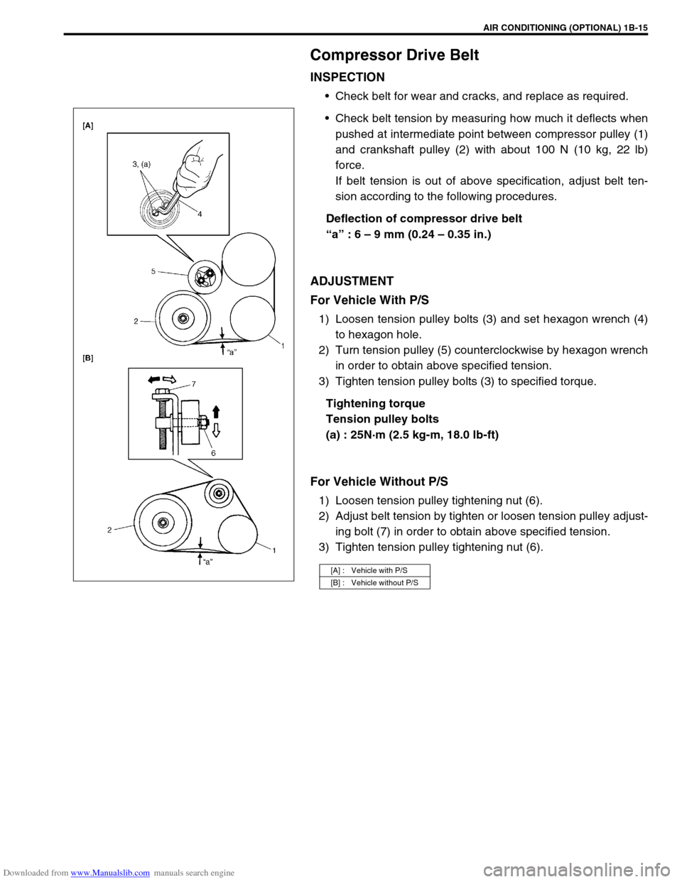
Check belt tension by measuring how much it deflects when
pushed at intermediate point between compressor pulley (1)
and crankshaft pulley (2) with about 100 N (10 kg, 22 lb)
force.
If belt tension is out of above specification, adjust belt ten-
sion according to the following procedures.
Deflection of compressor drive belt
“a” : 6 – 9 mm (0.24 – 0.35 in.)
ADJUSTMENT
For Vehicle With P/S
1) Loosen tension pulley bolts (3) and set hexagon wrench (4)
to hexagon hole.
2) Turn tension pulley (5) counterclockwise by hexagon wrench
in order to obtain above specified tension.
3) Tighten tension pulley bolts (3) to specified torque.
Tightening torque
Tension pulley bolts
(a) : 25N·m (2.5 kg-m, 18.0 lb-ft)
For Vehicle Without P/S
1) Loosen tension pulley tightening nut (6).
2) Adjust belt tension by tighten or loosen tension pulley adjust-
ing bolt (7) in order to obtain above specified tension.
3) Tighten tension pulley tightening nut (6).
[A] : Vehicle with P/S
[B] : Vehicle without P/S
Page 78 of 687
Downloaded from www.Manualslib.com manuals search engine AIR CONDITIONING (OPTIONAL) 1B-17
A/C System Inspection of ECM and ITS Cir-
cuits
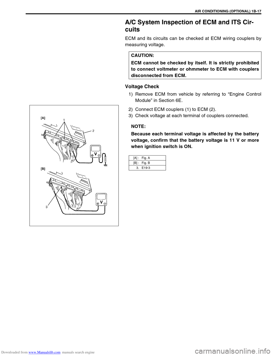
ECM and its circuits can be checked at ECM wiring couplers by
measuring voltage.
Voltage Check
1) Remove ECM from vehicle by referring to “Engine Control
Module” in Section 6E.
2) Connect ECM couplers (1) to ECM (2).
3) Check voltage at each terminal of couplers connected.CAUTION:
ECM cannot be checked by itself. It is strictly prohibited
to connect voltmeter or ohmmeter to ECM with couplers
disconnected from ECM.
NOTE:
Because each terminal voltage is affected by the battery
voltage, confirm that the battery voltage is 11 V or more
when ignition switch is ON.
[A] : Fig. A
[B] : Fig. B
3. E19-3
Page 82 of 687
Downloaded from www.Manualslib.com manuals search engine AIR CONDITIONING (OPTIONAL) 1B-21
Refrigerant Recovery, Evacuating and Charging
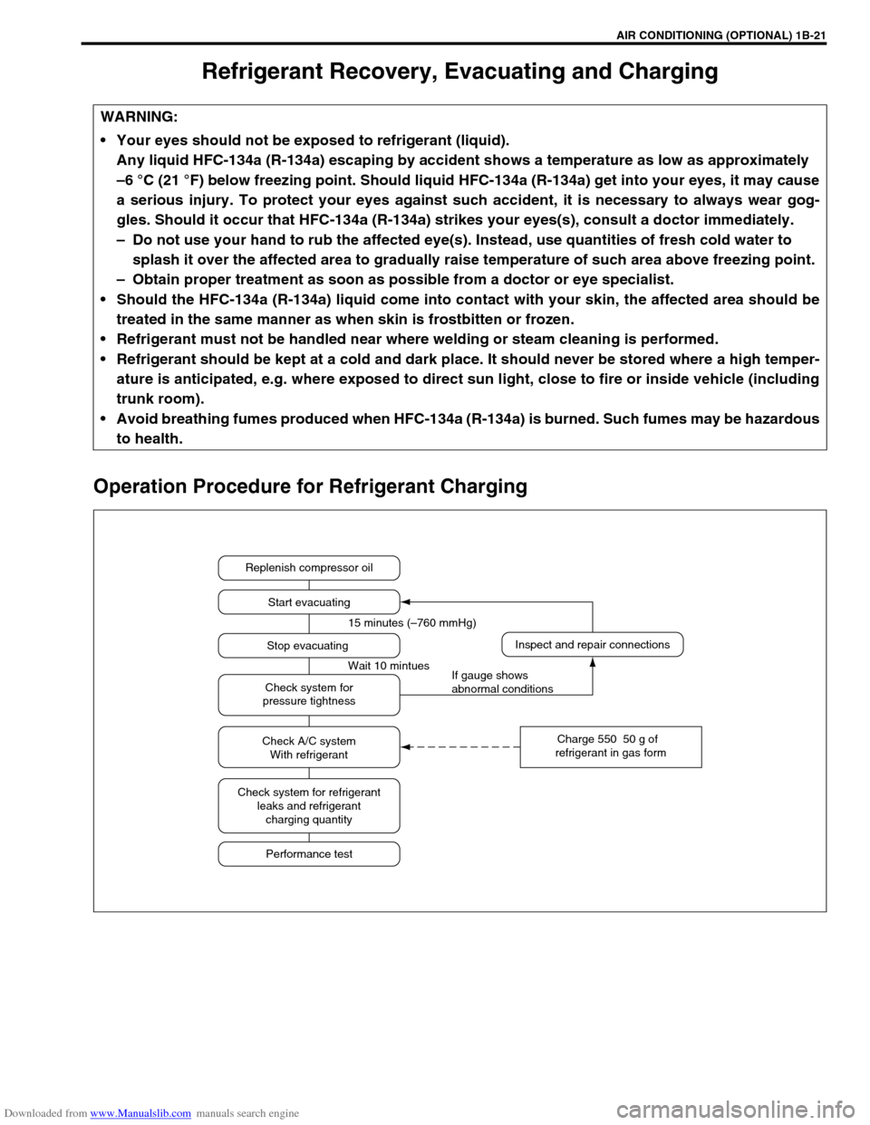
Operation Procedure for Refrigerant Charging
WARNING:
Your eyes should not be exposed to refrigerant (liquid).
Any liquid HFC-134a (R-134a) escaping by accident shows a temperature as low as approximately
–6 °C (21 °F) below freezing point. Should liquid HFC-134a (R-134a) get into your eyes, it may cause
a serious injury. To protect your eyes against such accident, it is necessary to always wear gog-
gles. Should it occur that HFC-134a (R-134a) strikes your eyes(s), consult a doctor immediately.
– Do not use your hand to rub the affected eye(s). Instead, use quantities of fresh cold water to
splash it over the affected area to gradually raise temperature of such area above freezing point.
– Obtain proper treatment as soon as possible from a doctor or eye specialist.
Should the HFC-134a (R-134a) liquid come into contact with your skin, the affected area should be
treated in the same manner as when skin is frostbitten or frozen.
Refrigerant must not be handled near where welding or steam cleaning is performed.
Refrigerant should be kept at a cold and dark place. It should never be stored where a high temper-
ature is anticipated, e.g. where exposed to direct sun light, close to fire or inside vehicle (including
trunk room).
Avoid breathing fumes produced when HFC-134a (R-134a) is burned. Such fumes may be hazardous
to health.
Replenish compressor oil
Start evacuating
Inspect and repair connections
Charge 550 50 g of
refrigerant in gas form Stop evacuating 15 minutes (–760 mmHg)
Wait 10 mintues
If gauge shows
abnormal conditions Check system for
pressure tightness
Check A/C system
With refrigerant
Check system for refrigerant
leaks and refrigerant
charging quantity
Performance test
Page 86 of 687

Downloaded from www.Manualslib.com manuals search engine AIR CONDITIONING (OPTIONAL) 1B-25
Charging
Charging procedure
The initial charging of the A/C system is performed from the high
pressure side with the engine stopped.
And next, this method must be followed by charging from the low
pressure side with the engine running.
1) Check to make sure that hoses are routed properly after
evacuating the system. CAUTION:
Always charge through low pressure side of A/C sys-
tem at after the initial charging is performed from the
high pressure side with the engine stopped.
Never charge to high pressure side of A/C system with
engine running.
Do not charge while compressor is hot.
When installing tap valve to refrigerant container to
make a hole there through, carefully follow directions
given by manufacturer.
A pressure gauge should always be used before and
during charging.
The refrigerant container should be emptied of refrig-
erant when discarding it.
The refrigerant container should not be heated up to
40 °C (104 °F) or over.
Refrigerant container should not be reversed in direc-
tion during charging. Reversing in direction causes liq-
uid refrigerant to enter compressor, causing troubles,
such as compression of liquid refrigerant and the like.
NOTE:
The air conditioning system contains HFC-134a (R-134a).
Described here is a method to charge the air conditioning
system with refrigerant from the refrigerant service con-
tainer.
When charging refrigerant recovered by using the refrig-
erant and recycling equipment (when recycling refriger-
ant), follow the procedure described in the equipment
manufacturer’s instruction manual.
Page 88 of 687
Downloaded from www.Manualslib.com manuals search engine AIR CONDITIONING (OPTIONAL) 1B-27
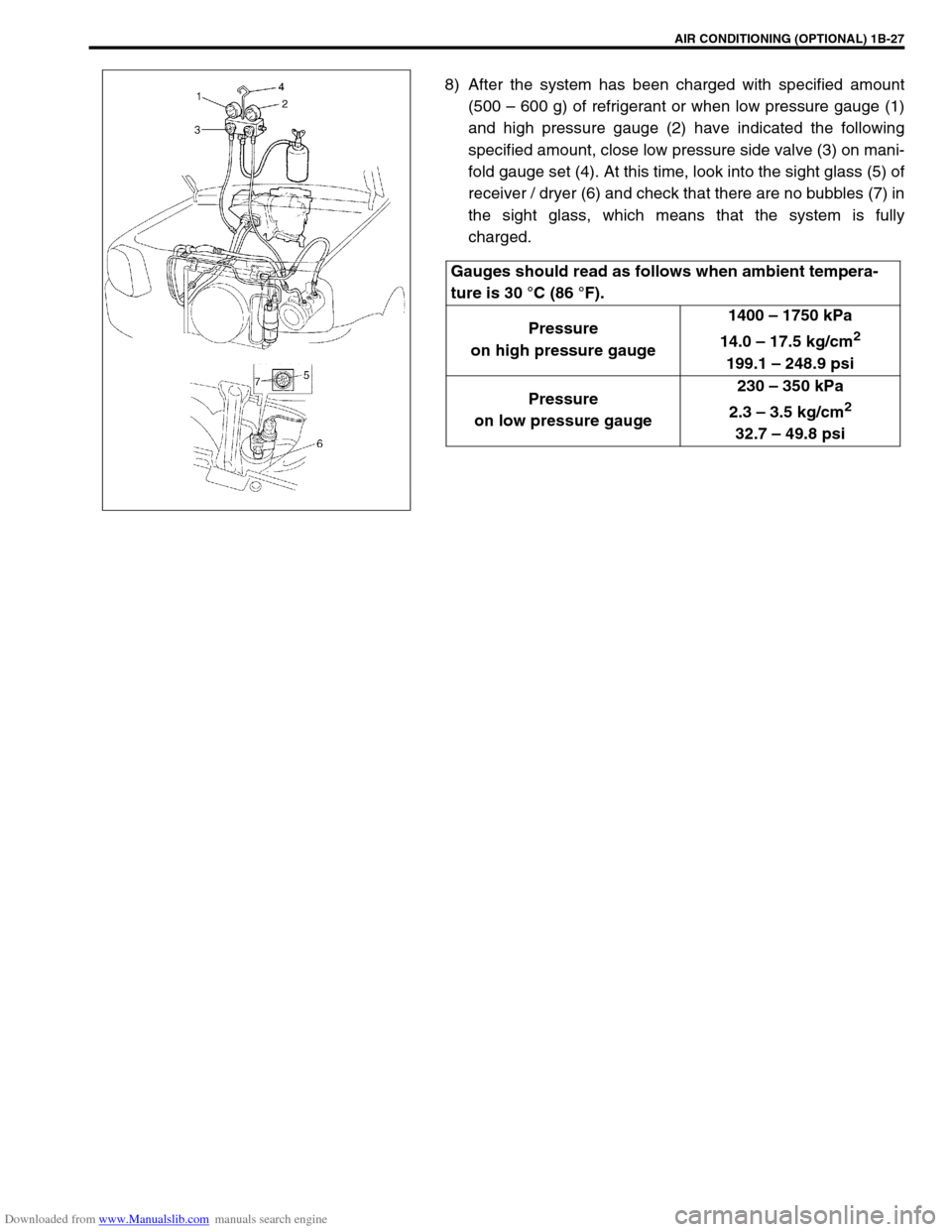
8) After the system has been charged with specified amount
(500 – 600 g) of refrigerant or when low pressure gauge (1)
and high pressure gauge (2) have indicated the following
specified amount, close low pressure side valve (3) on mani-
fold gauge set (4). At this time, look into the sight glass (5) of
receiver / dryer (6) and check that there are no bubbles (7) in
the sight glass, which means that the system is fully
charged.
Gauges should read as follows when ambient tempera-
ture is 30 °C (86 °F).
Pressure
on high pressure gauge1400 – 1750 kPa
14.0 – 17.5 kg/cm
2
199.1 – 248.9 psi
Pressure
on low pressure gauge230 – 350 kPa
2.3 – 3.5 kg/cm
2
32.7 – 49.8 psi
Page 91 of 687

Downloaded from www.Manualslib.com manuals search engine 1B-30 AIR CONDITIONING (OPTIONAL)
Handling refrigerant HFC-134a (R-134a)
Always wear goggles to protect your eyes.
Avoid you direct contact to liquid refrigerant.
Do not heat refrigerant container higher than 40 °C (104 °F).
Do not discharge refrigerant into atmosphere.
Do not allow liquid refrigerant to touch bright metals. Refrigerant combined with moisture is corrosive and
will tarnish surfaces of bright metals including chrome. WARNING:
Should refrigerant HFC-134a (R-134a) strike your eye(s), consult a doctor immediately.
Do not use your hand to rub affected eye(s). Instead, use quantities of fresh cold water to splash it
over affected area to thus gradually raise its temperature above the freezing point.
Obtain proper treatment as soon as possible from a doctor or eye specialist.
Should liquid refrigerant HFC-134a (R-134a) get on your skin, such affected part should be treated
in the same manner as when skin is frostbitten or frozen.
CAUTION:
The air conditioning system of this vehicle uses refrigerant HFC-134a (R-134a).
None of refrigerant, compressor oil and component parts is interchangeable between two types of
A/C: one using refrigerant HFC-134a (R-134a) and the other using refrigerant CFC-12 (R-12).
Be sure to check which refrigerant is used before any service work including inspection and mainte-
nance. For identification between these two types, refer to “Refrigerant Type” in this section. When
replenishing or changing refrigerant and compressor oil and when replacing parts, make sure that the
material or the part to be used is appropriate to the A/C installed in the vehicle being service.Use of
incorrect one will result in leakage of refrigerant, damage in parts or other faulty condition.
Page 92 of 687
Downloaded from www.Manualslib.com manuals search engine AIR CONDITIONING (OPTIONAL) 1B-31
Condenser Assembly
INSPECTION
Check the following.
Check clog of condenser fins.
If, any clogs are found, condenser fins should be washed
with water, and should be dried with compressed air.
Check condenser fins for leakage and breakage.
If any defects are found, repair or replace condenser.
Check condenser fittings for leakage.
If any defects are found, repair or replace condenser.
REMOVAL
1) Disconnect negative (–) cable at battery.
2) Recover refrigerant from A/C system by referring to “Recov-
ery” in this section.
3) Remove front bumper referring to “Front Bumper” in Section
8.
4) Disconnect A/C condenser cooling fan motor and dual pres-
sure switch connectors.
5) Remove radiator mounting bolts.
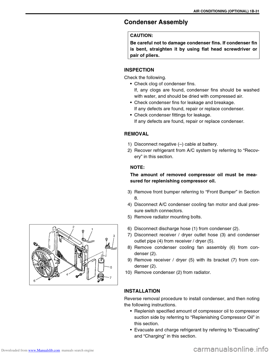
6) Disconnect discharge hose (1) from condenser (2).
7) Disconnect receiver / dryer outlet hose (3) and condenser
outlet pipe (4) from receiver / dryer (5).
8) Remove condenser cooling fan assembly (6) from con-
denser (2).
9) Remove receiver / dryer (5) with its bracket (7) from con-
denser (2).
10) Remove condenser (2) from radiator.
INSTALLATION
Reverse removal procedure to install condenser, and then noting
the following instructions.
Replenish specified amount of compressor oil to compressor
suction side by referring to “Replenishing Compressor Oil” in
this section.
Evacuate and charge refrigerant by referring to “Evacuating”
and “Charging” in this section. CAUTION:
Be careful not to damage condenser fins. If condenser fin
is bent, straighten it by using flat head screwdriver or
pair of pliers.
NOTE:
The amount of removed compressor oil must be mea-
sured for replenishing compressor oil.
Page 94 of 687
Downloaded from www.Manualslib.com manuals search engine AIR CONDITIONING (OPTIONAL) 1B-33
Condenser Cooling Fan Assembly
ASSEMBLY
INSPECTION
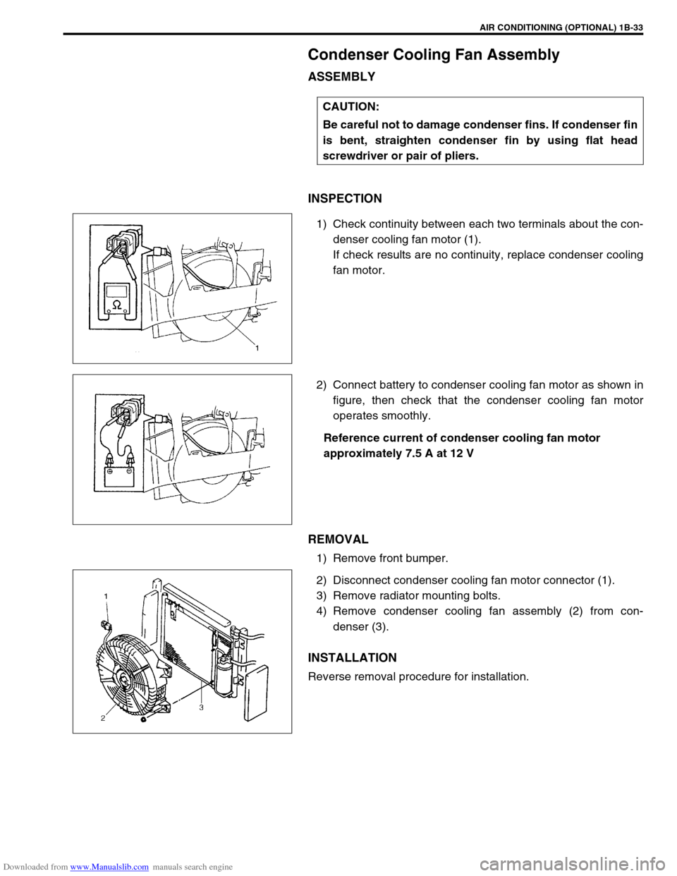
1) Check continuity between each two terminals about the con-
denser cooling fan motor (1).
If check results are no continuity, replace condenser cooling
fan motor.
2) Connect battery to condenser cooling fan motor as shown in
figure, then check that the condenser cooling fan motor
operates smoothly.
Reference current of condenser cooling fan motor
approximately 7.5 A at 12 V
REMOVAL
1) Remove front bumper.
2) Disconnect condenser cooling fan motor connector (1).
3) Remove radiator mounting bolts.
4) Remove condenser cooling fan assembly (2) from con-
denser (3).
INSTALLATION
Reverse removal procedure for installation.CAUTION:
Be careful not to damage condenser fins. If condenser fin
is bent, straighten condenser fin by using flat head
screwdriver or pair of pliers.