check engine SUZUKI JIMNY 2005 3.G Service User Guide
[x] Cancel search | Manufacturer: SUZUKI, Model Year: 2005, Model line: JIMNY, Model: SUZUKI JIMNY 2005 3.GPages: 687, PDF Size: 13.38 MB
Page 24 of 687
Downloaded from www.Manualslib.com manuals search engine GENERAL INFORMATION 0A-19
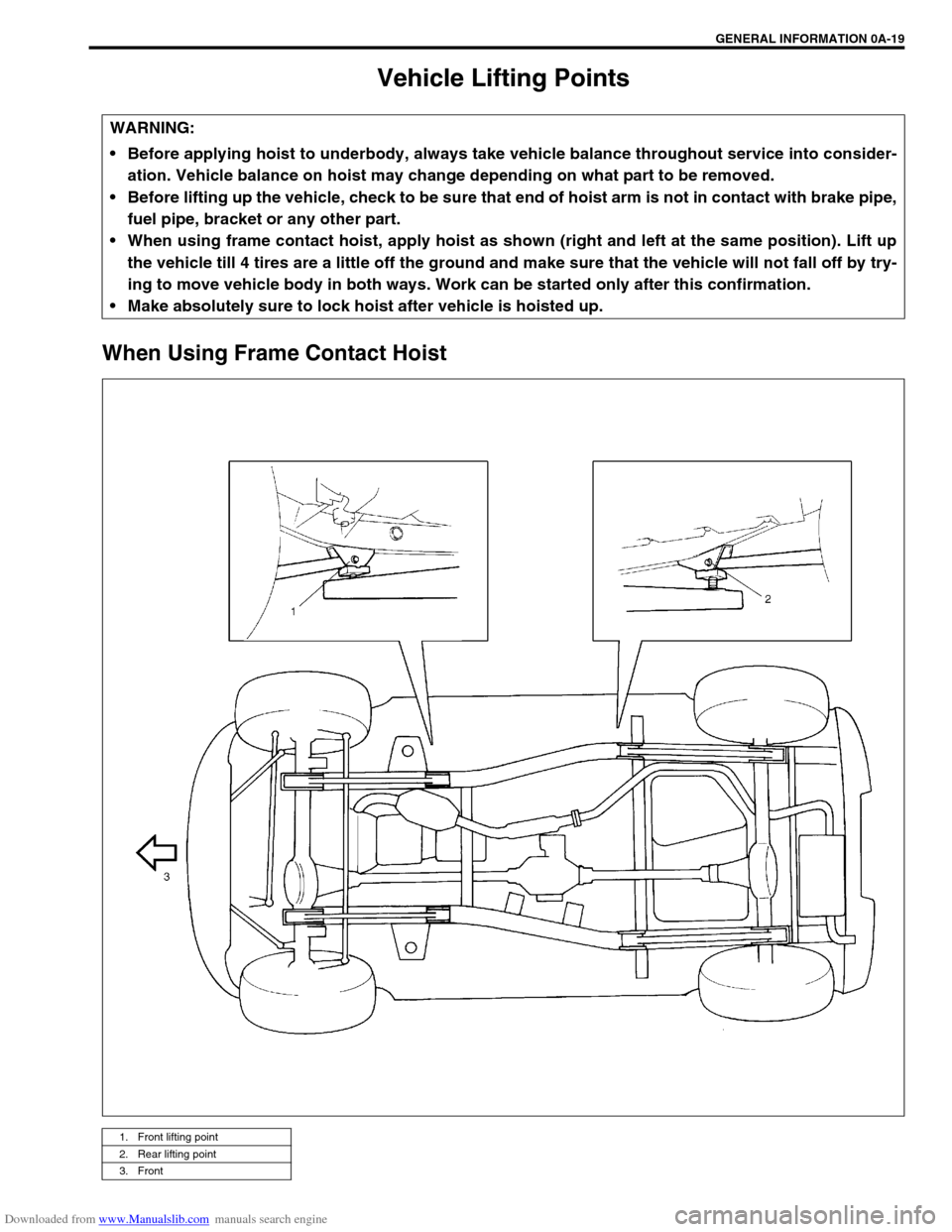
Vehicle Lifting Points
When Using Frame Contact Hoist
WARNING:
Before applying hoist to underbody, always take vehicle balance throughout service into consider-
ation. Vehicle balance on hoist may change depending on what part to be removed.
Before lifting up the vehicle, check to be sure that end of hoist arm is not in contact with brake pipe,
fuel pipe, bracket or any other part.
When using frame contact hoist, apply hoist as shown (right and left at the same position). Lift up
the vehicle till 4 tires are a little off the ground and make sure that the vehicle will not fall off by try-
ing to move vehicle body in both ways. Work can be started only after this confirmation.
Make absolutely sure to lock hoist after vehicle is hoisted up.
1. Front lifting point
2. Rear lifting point
3. Front
Page 25 of 687
Downloaded from www.Manualslib.com manuals search engine 0A-20 GENERAL INFORMATION
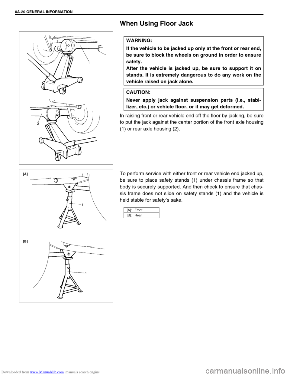
When Using Floor Jack
In raising front or rear vehicle end off the floor by jacking, be sure
to put the jack against the center portion of the front axle housing
(1) or rear axle housing (2).
To perform service with either front or rear vehicle end jacked up,
be sure to place safety stands (1) under chassis frame so that
body is securely supported. And then check to ensure that chas-
sis frame does not slide on safety stands (1) and the vehicle is
held stable for safety’s sake. WARNING:
If the vehicle to be jacked up only at the front or rear end,
be sure to block the wheels on ground in order to ensure
safety.
After the vehicle is jacked up, be sure to support it on
stands. It is extremely dangerous to do any work on the
vehicle raised on jack alone.
CAUTION:
Never apply jack against suspension parts (i.e., stabi-
lizer, etc.) or vehicle floor, or it may get deformed.
[A]: Front
[B]: Rear
Page 27 of 687
Downloaded from www.Manualslib.com manuals search engine 0A-22 GENERAL INFORMATION
LLH
LSPVLeft Hand
Load Sensing Proportioning Valve
TTBI
TCC
TCM
TP Sensor
TVV
TWC
2WDThrottle Body Fuel Injection
(Single-Point Fuel Injection, SPI)
Torque Converter Clutch
Transmission Control Module
(A/T Controller, A/T Control Mod-
ule)
Throttle Position Sensor
Thermal Vacuum Valve
(Thermal Vacuum Switching Valve,
TVSV, Bimetal Vacuum Switching
Valve, BVSV)
Three Way Catalytic Converter
(Three Way Catalyst)
2 Wheel Drive MMAF Sensor
MAP Sensor
Max
MFI
Min
MIL
M/TMass Air Flow Sensor
(Air Flow Sensor, AFS, Air Flow
Meter, AFM)
Manifold Absolute Pressure
Sensor (Pressure Sensor, PS)
Maximum
Multiport Fuel Injection
(Multipoint Fuel Injection)
Minimum
Malfunction Indicator Lamp
(“CHECK ENGINE” Light)
Manual Transmission
N NOx Nitrogen Oxides VVIN
VSSVehicle Identification Number
Vehicle Speed Sensor
OOBD
O/D
OHCOn-Board Diagnostic System
(Self-Diagnosis Function)
Overdrive
Over Head CamshaftWWU-OC
WU-TWCWarm Up Oxidation Catalytic
Converter
Warm Up Three Way Catalytic
Converter
PPNP
P/S
PSP Switch
PCM
PCVPark/Neutral Position
Power Steering
Power Steering Pressure Switch
(P/S Pressure Switch)
Powertrain Control Module
Positive Crankcase Ventilation
R RH Right Hand
SSAE
SDM
SFI
SOHCSociety of Automotive Engineers
Sensing and Diagnostic Module
(Air bag controller, Air bag control
module)
Sequential Multiport Fuel Injection
Single Over Head Camshaft
Page 36 of 687
Downloaded from www.Manualslib.com manuals search engine MAINTENANCE AND LUBRICATION 0B-5
Maintenance Service
Engine
Drive Belt
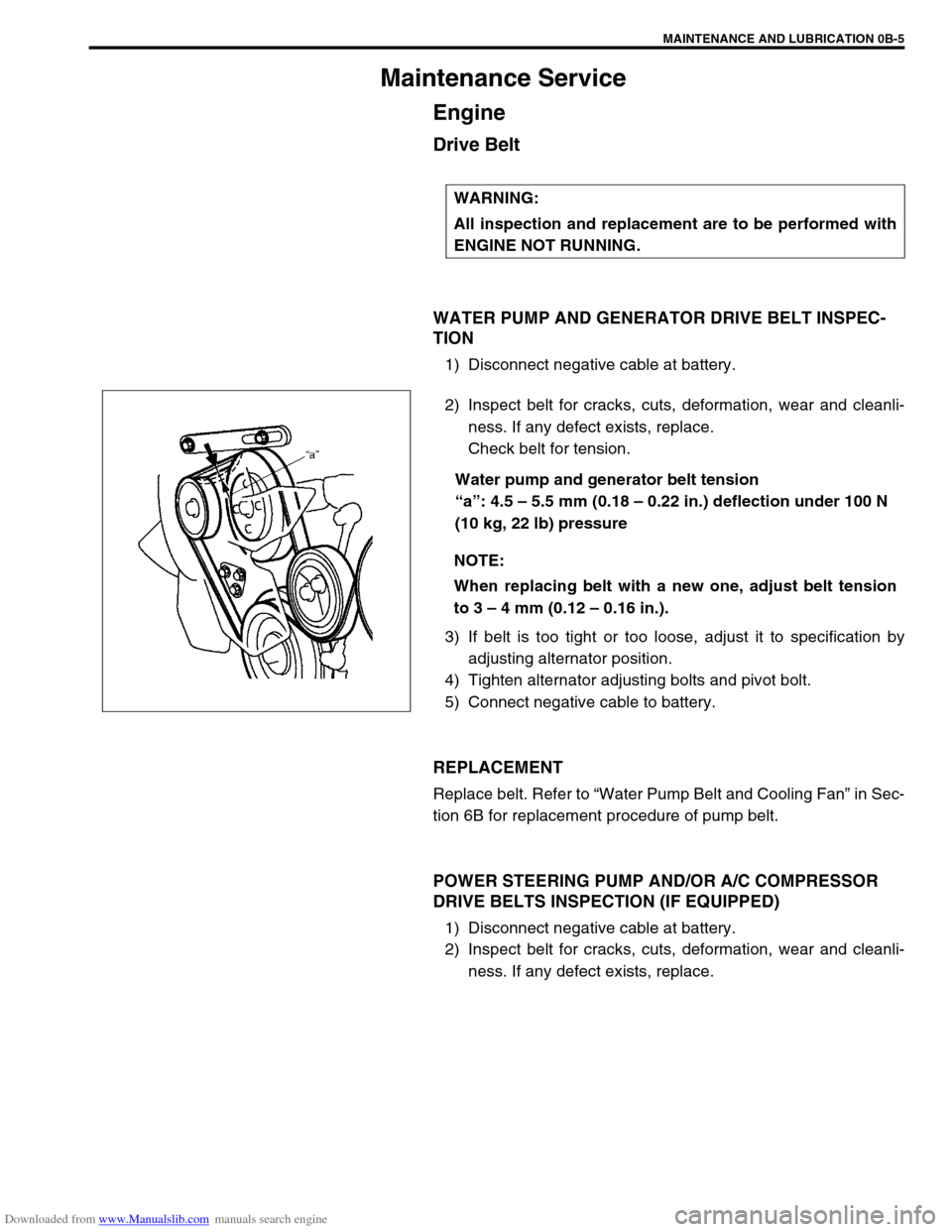
WATER PUMP AND GENERATOR DRIVE BELT INSPEC-
TION
1) Disconnect negative cable at battery.
2) Inspect belt for cracks, cuts, deformation, wear and cleanli-
ness. If any defect exists, replace.
Check belt for tension.
Water pump and generator belt tension
“a”: 4.5 – 5.5 mm (0.18 – 0.22 in.) deflection under 100 N
(10 kg, 22 lb) pressure
3) If belt is too tight or too loose, adjust it to specification by
adjusting alternator position.
4) Tighten alternator adjusting bolts and pivot bolt.
5) Connect negative cable to battery.
REPLACEMENT
Replace belt. Refer to “Water Pump Belt and Cooling Fan” in Sec-
tion 6B for replacement procedure of pump belt.
POWER STEERING PUMP AND/OR A/C COMPRESSOR
DRIVE BELTS INSPECTION (IF EQUIPPED)
1) Disconnect negative cable at battery.
2) Inspect belt for cracks, cuts, deformation, wear and cleanli-
ness. If any defect exists, replace. WARNING:
All inspection and replacement are to be performed with
ENGINE NOT RUNNING.
NOTE:
When replacing belt with a new one, adjust belt tension
to 3 – 4 mm (0.12 – 0.16 in.).
Page 37 of 687
Downloaded from www.Manualslib.com manuals search engine 0B-6 MAINTENANCE AND LUBRICATION
3) Check belt for tension.
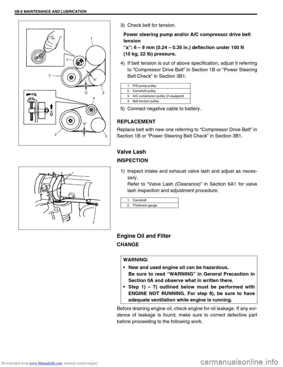
Power steering pump and/or A/C compressor drive belt
tension
“a”: 6 – 9 mm (0.24 – 0.35 in.) deflection under 100 N
(10 kg, 22 lb) pressure.
4) If belt tension is out of above specification, adjust it referring
to “Compressor Drive Belt” in Section 1B or “Power Steering
Belt Check” in Section 3B1.
5) Connect negative cable to battery.
REPLACEMENT
Replace belt with new one referring to “Compressor Drive Belt” in
Section 1B or “Power Steering Belt Check” in Section 3B1.
Valve Lash
INSPECTION
1) Inspect intake and exhaust valve lash and adjust as neces-
sary.
Refer to “Valve Lash (Clearance)” in Section 6A1 for valve
lash inspection and adjustment procedure.
Engine Oil and Filter
CHANGE
Before draining engine oil, check engine for oil leakage. If any evi-
dence of leakage is found, make sure to correct defective part
before proceeding to the following work.
1. P/S pump pulley
2. Camshaft pulley
3. A/C compressor pulley (if equipped)
4. Belt tension pulley
1. Camshaft
2. Thickness gauge
WARNING:
New and used engine oil can be hazardous.
Be sure to read “WARNING” in General Precaution in
Section 0A and observe what in written there.
Step 1) – 7) outlined below must be performed with
ENGINE NOT RUNNING. For step 8), be sure to have
adequate ventilation while engine is running.
Page 39 of 687
Downloaded from www.Manualslib.com manuals search engine 0B-8 MAINTENANCE AND LUBRICATION
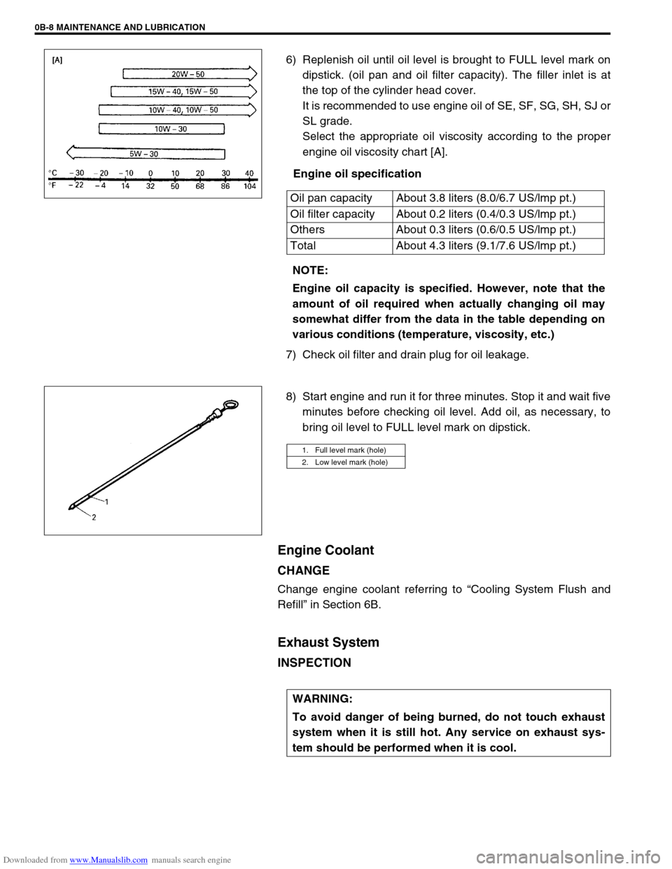
6) Replenish oil until oil level is brought to FULL level mark on
dipstick. (oil pan and oil filter capacity). The filler inlet is at
the top of the cylinder head cover.
It is recommended to use engine oil of SE, SF, SG, SH, SJ or
SL grade.
Select the appropriate oil viscosity according to the proper
engine oil viscosity chart [A].
Engine oil specification
7) Check oil filter and drain plug for oil leakage.
8) Start engine and run it for three minutes. Stop it and wait five
minutes before checking oil level. Add oil, as necessary, to
bring oil level to FULL level mark on dipstick.
Engine Coolant
CHANGE
Change engine coolant referring to “Cooling System Flush and
Refill” in Section 6B.
Exhaust System
INSPECTION
Oil pan capacity About 3.8 liters (8.0/6.7 US/lmp pt.)
Oil filter capacity About 0.2 liters (0.4/0.3 US/lmp pt.)
Others About 0.3 liters (0.6/0.5 US/lmp pt.)
Total About 4.3 liters (9.1/7.6 US/lmp pt.)
NOTE:
Engine oil capacity is specified. However, note that the
amount of oil required when actually changing oil may
somewhat differ from the data in the table depending on
various conditions (temperature, viscosity, etc.)
1. Full level mark (hole)
2. Low level mark (hole)
WARNING:
To avoid danger of being burned, do not touch exhaust
system when it is still hot. Any service on exhaust sys-
tem should be performed when it is cool.
Page 40 of 687
Downloaded from www.Manualslib.com manuals search engine MAINTENANCE AND LUBRICATION 0B-9
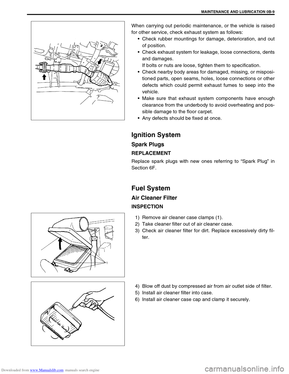
When carrying out periodic maintenance, or the vehicle is raised
for other service, check exhaust system as follows:
Check rubber mountings for damage, deterioration, and out
of position.
Check exhaust system for leakage, loose connections, dents
and damages.
If bolts or nuts are loose, tighten them to specification.
Check nearby body areas for damaged, missing, or misposi-
tioned parts, open seams, holes, loose connections or other
defects which could permit exhaust fumes to seep into the
vehicle.
Make sure that exhaust system components have enough
clearance from the underbody to avoid overheating and pos-
sible damage to the floor carpet.
Any defects should be fixed at once.
Ignition System
Spark Plugs
REPLACEMENT
Replace spark plugs with new ones referring to “Spark Plug” in
Section 6F.
Fuel System
Air Cleaner Filter
INSPECTION
1) Remove air cleaner case clamps (1).
2) Take cleaner filter out of air cleaner case.
3) Check air cleaner filter for dirt. Replace excessively dirty fil-
ter.
4) Blow off dust by compressed air from air outlet side of filter.
5) Install air cleaner filter into case.
6) Install air cleaner case cap and clamp it securely.
Page 41 of 687
Downloaded from www.Manualslib.com manuals search engine 0B-10 MAINTENANCE AND LUBRICATION
REPLACEMENT
Replace air cleaner filter with new one according to steps 1), 2)
and 5), 6) of inspection procedure.
Fuel Lines and Connections
INSPECTION
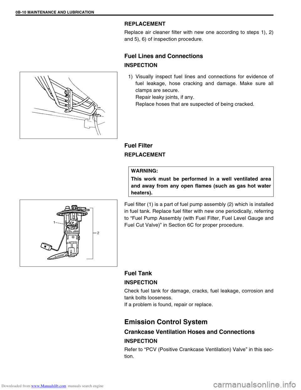
1) Visually inspect fuel lines and connections for evidence of
fuel leakage, hose cracking and damage. Make sure all
clamps are secure.
Repair leaky joints, if any.
Replace hoses that are suspected of being cracked.
Fuel Filter
REPLACEMENT
Fuel filter (1) is a part of fuel pump assembly (2) which is installed
in fuel tank. Replace fuel filter with new one periodically, referring
to “Fuel Pump Assembly (with Fuel Filter, Fuel Level Gauge and
Fuel Cut Valve)” in Section 6C for proper procedure.
Fuel Tank
INSPECTION
Check fuel tank for damage, cracks, fuel leakage, corrosion and
tank bolts looseness.
If a problem is found, repair or replace.
Emission Control System
Crankcase Ventilation Hoses and Connections
INSPECTION
Refer to “PCV (Positive Crankcase Ventilation) Valve” in this sec-
tion.
WARNING:
This work must be performed in a well ventilated area
and away from any open flames (such as gas hot water
heaters).
Page 42 of 687
Downloaded from www.Manualslib.com manuals search engine MAINTENANCE AND LUBRICATION 0B-11
PCV (Positive Crankcase Ventilation) Valve
INSPECTION
Check crankcase ventilation hose and PCV hose for leaks, cracks
or clog, and PCV valve for stick or clog. Refer to “PCV System” of
Section 6E for PCV valve checking procedure.
Fuel Evaporative Emission Control System
INSPECTION
1) Visually inspect hoses for cracks, damage, or excessive
bends. Inspect all clamps for damage and proper position.
2) Check EVAP canister for operation and clog, referring to
“Evaporative Emission (EVAP) Control System” in Section
6E.
If a malfunction is found, repair or replace.
Chassis and Body
Clutch
INSPECTION
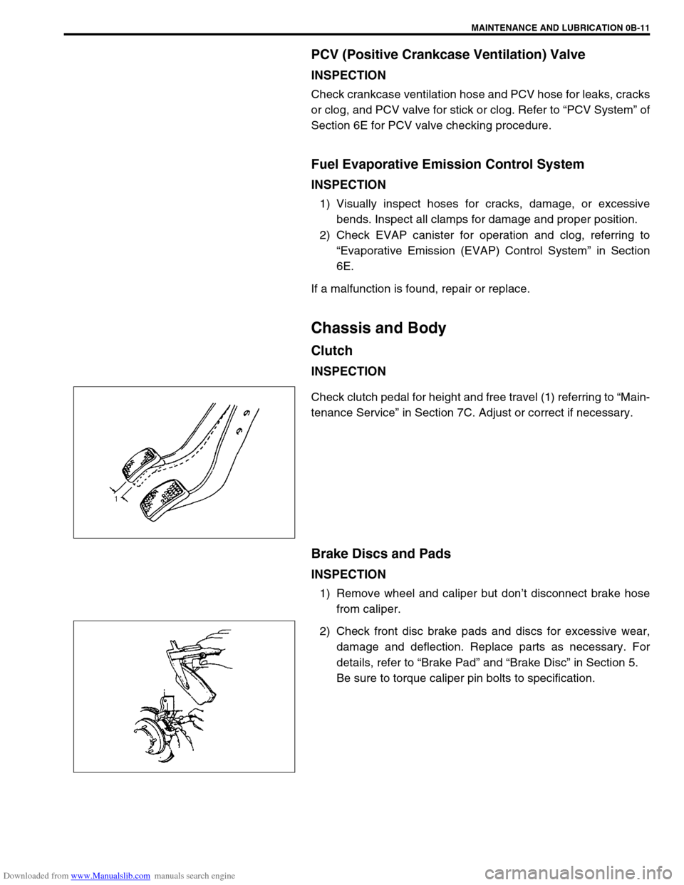
Check clutch pedal for height and free travel (1) referring to “Main-
tenance Service” in Section 7C. Adjust or correct if necessary.
Brake Discs and Pads
INSPECTION
1) Remove wheel and caliper but don’t disconnect brake hose
from caliper.
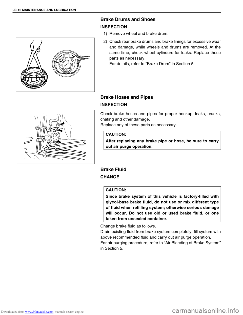
2) Check front disc brake pads and discs for excessive wear,
damage and deflection. Replace parts as necessary. For
details, refer to “Brake Pad” and “Brake Disc” in Section 5.
Be sure to torque caliper pin bolts to specification.
Page 43 of 687
Downloaded from www.Manualslib.com manuals search engine 0B-12 MAINTENANCE AND LUBRICATION
Brake Drums and Shoes
INSPECTION
1) Remove wheel and brake drum.
2) Check rear brake drums and brake linings for excessive wear
and damage, while wheels and drums are removed. At the
same time, check wheel cylinders for leaks. Replace these
parts as necessary.
For details, refer to “Brake Drum” in Section 5.
Brake Hoses and Pipes
INSPECTION
Check brake hoses and pipes for proper hookup, leaks, cracks,
chafing and other damage.
Replace any of these parts as necessary.
Brake Fluid
CHANGE
Change brake fluid as follows.
Drain existing fluid from brake system completely, fill system with
above recommended fluid and carry out air purge operation.
For air purging procedure, refer to “Air Bleeding of Brake System”
in Section 5.
CAUTION:
After replacing any brake pipe or hose, be sure to carry
out air purge operation.
CAUTION:
Since brake system of this vehicle is factory-filled with
glycol-base brake fluid, do not use or mix different type
of fluid when refilling system; otherwise serious damage
will occur. Do not use old or used brake fluid, or one
taken from unsealed container.