relay SUZUKI JIMNY 2005 3.G Service Owner's Manual
[x] Cancel search | Manufacturer: SUZUKI, Model Year: 2005, Model line: JIMNY, Model: SUZUKI JIMNY 2005 3.GPages: 687, PDF Size: 13.38 MB
Page 403 of 687
Downloaded from www.Manualslib.com manuals search engine 6-46 ENGINE GENERAL INFORMATION AND DIAGNOSIS
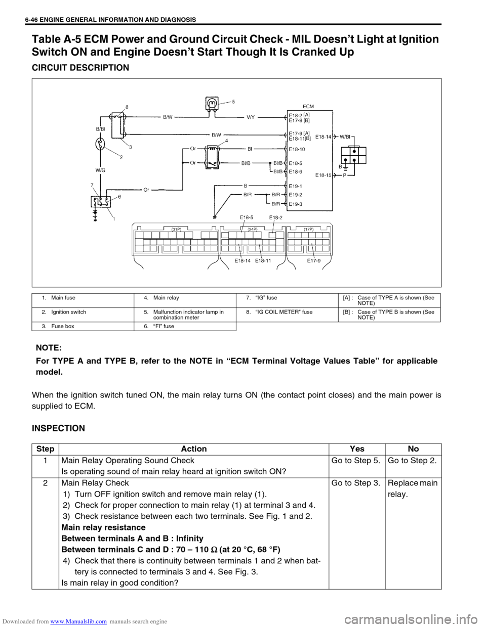
Table A-5 ECM Power and Ground Circuit Check - MIL Doesn’t Light at Ignition
Switch ON and Engine Doesn’t Start Though It Is Cranked Up
CIRCUIT DESCRIPTION
When the ignition switch tuned ON, the main relay turns ON (the contact point closes) and the main power is
supplied to ECM.
INSPECTION
1. Main fuse 4. Main relay 7.“IG” fuse [A] : Case of TYPE A is shown (See
NOTE)
2. Ignition switch 5. Malfunction indicator lamp in
combination meter8.“IG COIL METER” fuse [B] : Case of TYPE B is shown (See
NOTE)
3. Fuse box 6.“FI” fuse
NOTE:
For TYPE A and TYPE B, refer to the NOTE in “ECM Terminal Voltage Values Table” for applicable
model.
Step Action Yes No
1 Main Relay Operating Sound Check
Is operating sound of main relay heard at ignition switch ON?Go to Step 5. Go to Step 2.
2 Main Relay Check
1) Turn OFF ignition switch and remove main relay (1).
2) Check for proper connection to main relay (1) at terminal 3 and 4.
3) Check resistance between each two terminals. See Fig. 1 and 2.
Main relay resistance
Between terminals A and B : Infinity
Between terminals C and D : 70 – 110
Ω
Ω Ω Ω (at 20 °C, 68 °F)
4) Check that there is continuity between terminals 1 and 2 when bat-
tery is connected to terminals 3 and 4. See Fig. 3.
Is main relay in good condition?Go to Step 3. Replace main
relay.
Page 404 of 687
![SUZUKI JIMNY 2005 3.G Service Owners Manual Downloaded from www.Manualslib.com manuals search engine ENGINE GENERAL INFORMATION AND DIAGNOSIS 6-47
[A] Fig. 1 for Step 2 and 3 / [B] Fig. 2 for Step 2 / [C] Fig. 3 for Step 23 Fuse Check
Is main � SUZUKI JIMNY 2005 3.G Service Owners Manual Downloaded from www.Manualslib.com manuals search engine ENGINE GENERAL INFORMATION AND DIAGNOSIS 6-47
[A] Fig. 1 for Step 2 and 3 / [B] Fig. 2 for Step 2 / [C] Fig. 3 for Step 23 Fuse Check
Is main �](/img/20/7588/w960_7588-403.png)
Downloaded from www.Manualslib.com manuals search engine ENGINE GENERAL INFORMATION AND DIAGNOSIS 6-47
[A] Fig. 1 for Step 2 and 3 / [B] Fig. 2 for Step 2 / [C] Fig. 3 for Step 23 Fuse Check
Is main “FI” fuse in good condition? See Fig. 1.Go to Step 4. Check for
short in cir-
cuits con-
nected to this
fuse.
4 ECM Power Circuit Check
1) Turn OFF ignition switch, disconnect connectors from ECM and
install main relay.
2) Check for proper connection to ECM at terminals E17-9 (Case of
TYPE A) (See NOTE) or E18-11 (Case of TYPE B) (See NOTE),
E18-10, E18-5 and E18-6.
3) If OK, then measure voltage between terminal E18-10 and ground,
E17-9 (Case of TYPE A) (See NOTE) or E18-11 (Case of TYPE B)
(See NOTE) and ground with ignition switch ON.
Is each voltage 10 – 14 V?Go to Step 5.“B/W”, “Or” or
“Bl/B” circuit
open.
5 ECM Power Circuit Check
1) Using service wire, ground terminal E18-10 and measure voltage
between terminal E18-5 and ground at ignition switch ON.
Is it 10 – 14 V?Check
ground cir-
cuits “B” and
“B/R” for
open.
If OK, then
substitute a
known-good
ECM and
recheck.Go to Step 6.
6 Is operating sound of main relay heard in Step 1? Go to Step 7.“Bl/B” or “B/
R” wire open.
7 Main Relay Check
1) Check main relay according to procedure in Step 2.
Is main relay in good condition?“Or” or “Bl/B”
wire open.Replace main
relay. Step Action Yes No
2.“F1” fuse
Page 449 of 687
Downloaded from www.Manualslib.com manuals search engine 6-92 ENGINE GENERAL INFORMATION AND DIAGNOSIS
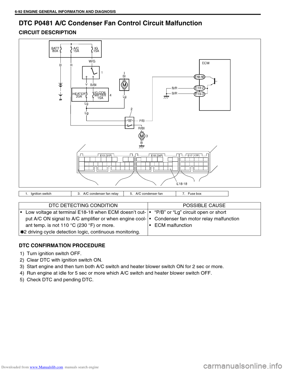
DTC P0481 A/C Condenser Fan Control Circuit Malfunction
CIRCUIT DESCRIPTION
DTC CONFIRMATION PROCEDURE
1) Turn ignition switch OFF.
2) Clear DTC with ignition switch ON.
3) Start engine and then turn both A/C switch and heater blower switch ON for 2 sec or more.
4) Run engine at idle for 5 sec or more which A/C switch and heater blower switch OFF.
5) Check DTC and pending DTC.
1. Ignition switch 3. A/C condenser fan relay 5. A/C condenser fan 7. Fuse box
DTC DETECTING CONDITION POSSIBLE CAUSE
Low voltage at terminal E18-18 when ECM doesn’t out-
put A/C ON signal to A/C amplifier or when engine cool-
ant temp. is not 110 °C (230 °F) or more.
✱
✱✱ ✱2 driving cycle detection logic, continuous monitoring.“P/B” or “Lg” circuit open or short
Condenser fan motor relay malfunction
ECM malfunction
Page 450 of 687
![SUZUKI JIMNY 2005 3.G Service Owners Manual Downloaded from www.Manualslib.com manuals search engine ENGINE GENERAL INFORMATION AND DIAGNOSIS 6-93
INSPECTION
[A] Fig. 1 for Step 3 / [B] Fig. 2 for Step 3Step Action Yes No
1Was “Engine Diag. F SUZUKI JIMNY 2005 3.G Service Owners Manual Downloaded from www.Manualslib.com manuals search engine ENGINE GENERAL INFORMATION AND DIAGNOSIS 6-93
INSPECTION
[A] Fig. 1 for Step 3 / [B] Fig. 2 for Step 3Step Action Yes No
1Was “Engine Diag. F](/img/20/7588/w960_7588-449.png)
Downloaded from www.Manualslib.com manuals search engine ENGINE GENERAL INFORMATION AND DIAGNOSIS 6-93
INSPECTION
[A] Fig. 1 for Step 3 / [B] Fig. 2 for Step 3Step Action Yes No
1Was “Engine Diag. Flow Table” performed? Go to Step 2. Go to “Engine Diag.
Flow Table”.
2 Check A/C Condenser Fan Control Relay and its
Circuit.
1) Turn ignition switch ON.
2) Check for voltage at terminal E18-18 of ECM
connector connected, under following condition.
When A/C switch turns OFF : 10 – 14 V
Is voltage as specified?Intermittent trouble or
faulty ECM.
Check for intermittent
referring to “Intermittent
and Poor Connection” in
Section 0A.Go to Step 3.
3 Check A/C Condenser Fan Control Relay.
1) Turn ignition switch OFF and remove A/C con-
denser fan control relay (1). See Fig.1.
2) Check for proper connection to the relay at “P/B”
and “Lg” wire terminals.
3) If OK, then measure resistance between termi-
nals C and D. See Fig.2.
Is it 70 - 110Ω?“Lg” or “P/B” circuit open
or short.
If wires and connections
are OK, substitute a
known-good ECM and
recheck.Replace A/C con-
denser fan control
relay.
Page 453 of 687
Downloaded from www.Manualslib.com manuals search engine 6-96 ENGINE GENERAL INFORMATION AND DIAGNOSIS
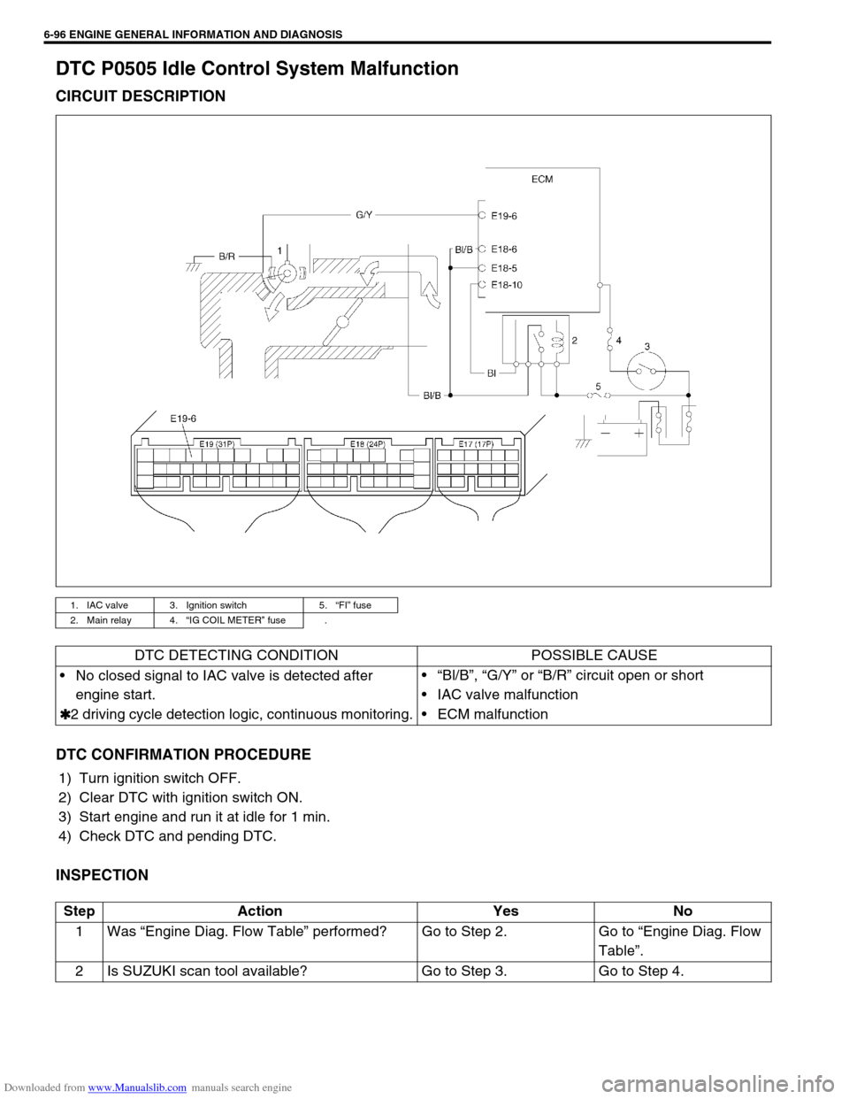
DTC P0505 Idle Control System Malfunction
CIRCUIT DESCRIPTION
DTC CONFIRMATION PROCEDURE
1) Turn ignition switch OFF.
2) Clear DTC with ignition switch ON.
3) Start engine and run it at idle for 1 min.
4) Check DTC and pending DTC.
INSPECTION
1. IAC valve 3. Ignition switch 5.“FI” fuse
2. Main relay 4.“IG COIL METER” fuse .
DTC DETECTING CONDITION POSSIBLE CAUSE
No closed signal to IAC valve is detected after
engine start.
✱
✱✱ ✱2 driving cycle detection logic, continuous monitoring.“Bl/B”, “G/Y” or “B/R” circuit open or short
IAC valve malfunction
ECM malfunction
Step Action Yes No
1Was “Engine Diag. Flow Table” performed? Go to Step 2. Go to “Engine Diag. Flow
Table”.
2 Is SUZUKI scan tool available? Go to Step 3. Go to Step 4.
Page 467 of 687
Downloaded from www.Manualslib.com manuals search engine 6-110 ENGINE GENERAL INFORMATION AND DIAGNOSIS
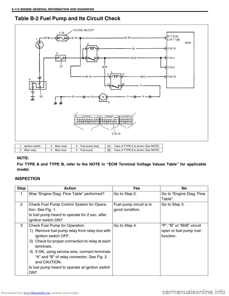
Table B-2 Fuel Pump and Its Circuit Check
INSPECTION
1. Ignition switch 3. Main relay 5. Fuel pump relay [A] : Case of TYPE A is shown (See NOTE)
2. Main relay 4. Main fuse 6. Fuel pump [B] : Case of TYPE B is shown (See NOTE)
NOTE:
For TYPE A and TYPE B, refer to the NOTE in “ECM Terminal Voltage Values Table” for applicable
model.
Step Action Yes No
1Was “Engine Diag. Flow Table” performed? Go to Step 2. Go to “Engine Diag. Flow
Table”.
2 Check Fuel Pump Control System for Opera-
tion. See Fig. 1.
Is fuel pump heard to operate for 2 sec. after
ignition switch ON?Fuel pump circuit is in
good condition.Go to Step 3.
3 Check Fuel Pump for Operation.
1) Remove fuel pump relay from relay box with
ignition switch OFF.
2) Check for proper connection to relay at each
terminals.
3) If OK, using service wire, connect terminals
“A” and “B” of relay connector. See Fig. 2
and CAUTION.
Is fuel pump heard to operate at ignition switch
ON?Go to Step 4.“P”, “B” or “Bl/B” circuit
open or fuel pump mal-
function.
Page 468 of 687
![SUZUKI JIMNY 2005 3.G Service Owners Manual Downloaded from www.Manualslib.com manuals search engine ENGINE GENERAL INFORMATION AND DIAGNOSIS 6-111
[A] Fig. 1 for Step 2 / [B] Fig. 2 for Step 3 / [C] Fig. 3 for Step 44 Check Fuel Pump Relay for SUZUKI JIMNY 2005 3.G Service Owners Manual Downloaded from www.Manualslib.com manuals search engine ENGINE GENERAL INFORMATION AND DIAGNOSIS 6-111
[A] Fig. 1 for Step 2 / [B] Fig. 2 for Step 3 / [C] Fig. 3 for Step 44 Check Fuel Pump Relay for](/img/20/7588/w960_7588-467.png)
Downloaded from www.Manualslib.com manuals search engine ENGINE GENERAL INFORMATION AND DIAGNOSIS 6-111
[A] Fig. 1 for Step 2 / [B] Fig. 2 for Step 3 / [C] Fig. 3 for Step 44 Check Fuel Pump Relay for Operation.
1) Check resistance between each two termi-
nals of fuel pump relay. See Fig.3.
Fuel pump relay resistance
Between terminals “A” and “B” : Infinity
Between terminals “C” and “D”: 100 – 150
Ω
ΩΩ Ω
2) Check that there is continuity between ter-
minals “A” and “B” when battery is con-
nected to terminals “C” and “D”. See Fig. 3.
Is fuel pump relay in good condition?“W/G” circuit open or poor
E18-19 connection.
If wire and connection are
OK, substitute a known-
good ECM and recheck.Replace fuel pump
relay. Step Action Yes No
CAUTION:
Check to make sure that connection is made between correct terminals. Wrong connection can cause
damage to ECM, wire harness, etc.
Page 471 of 687
Downloaded from www.Manualslib.com manuals search engine 6-114 ENGINE GENERAL INFORMATION AND DIAGNOSIS
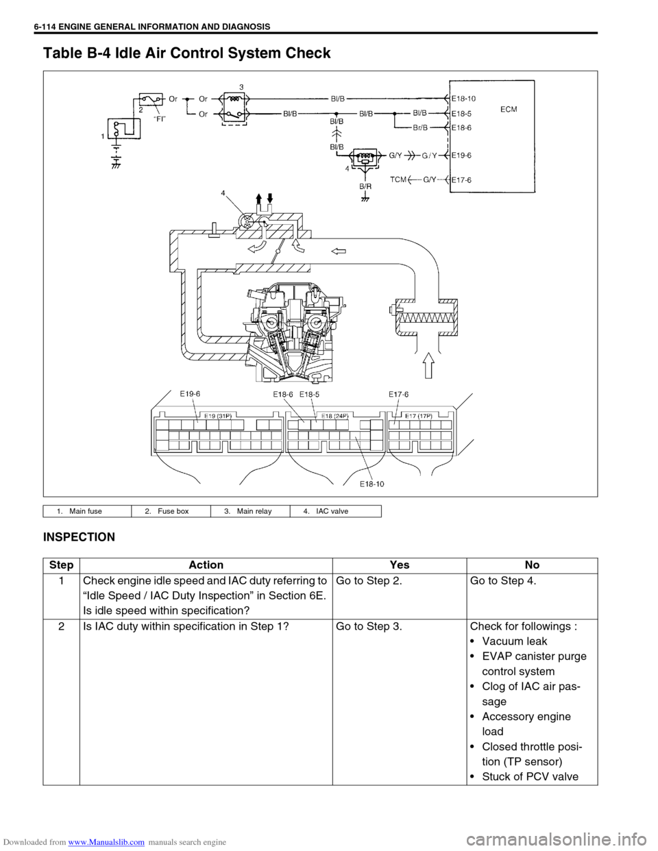
Table B-4 Idle Air Control System Check
INSPECTION
1. Main fuse 2. Fuse box 3. Main relay 4. IAC valve
Step Action Yes No
1 Check engine idle speed and IAC duty referring to
“Idle Speed / IAC Duty Inspection” in Section 6E.
Is idle speed within specification?Go to Step 2. Go to Step 4.
2 Is IAC duty within specification in Step 1? Go to Step 3. Check for followings :
Vacuum leak
EVAP canister purge
control system
Clog of IAC air pas-
sage
Accessory engine
load
Closed throttle posi-
tion (TP sensor)
Stuck of PCV valve
Page 478 of 687

Downloaded from www.Manualslib.com manuals search engine ENGINE GENERAL INFORMATION AND DIAGNOSIS 6-121
TAble B-7 A/C Condenser Fan Control System Check
INSPECTION
Step Action Yes No
1 Check Fan Control System.
1) Connect scan tool to DLC with ignition switch OFF. See
Fig. 1.
2) Start engine and select “DATA LIST” mode on scan tool.
3) Warm up engine until coolant temp. is 110 °C, 230 °F or
higher and A/C switch turn OFF. (If engine coolant temp.
does not rise, check engine cooling system or ECT sen-
sor.)
Is A/C condenser fan started when engine coolant temp.
reached above temp.?A/C condenser fan con-
trol system is in good
condition.Go to Step 2.
2 Check A/C Condenser Fan Relay and Its Circuit.
1) Check DTC and pending DTC with scan tool.
Is DTC P0481 displayed?Go to DTC P0481 Diag.
Flow Table.Go to Step 3.
3 Check A/C Condenser Fan Relay (1).
1) Turn ignition switch OFF and remove A/C condenser fan
relay.
2) Check for proper connection to relay at terminals “A”
and “B”.
3) If OK, check that there is continuity between “A” and “B”
when battery is connected to terminals “C” and “D”. See
Fig. 2.
Is check result satisfactory?Go to Step 4. Replace A/C
condenser fan
relay.
Page 606 of 687

Downloaded from www.Manualslib.com manuals search engine ENGINE AND EMISSION CONTROL SYSTEM 6E-1
6F1
6F2
6G
7C1
7D
7E
7A
7A1
7B1
7C1
7D
7E
7F
8A
8B
8C
8D
6H
6E
10
10A
10B
SECTION 6E
ENGINE AND EMISSION CONTROL SYSTEM
CONTENTS
General Description ....................................... 6E-3
Air Intake System ......................................... 6E-5
Fuel Delivery System ................................... 6E-6
Fuel pump ................................................ 6E-6
Electronic Control System ............................ 6E-7
Engine & emission control input / output
table.......................................................... 6E-8
On-Vehicle Service....................................... 6E-15
Accelerator cable adjustment ................. 6E-15
Idle speed / idle air control (IAC) duty
inspection ............................................... 6E-15
Idle mixture inspection / adjustment
(vehicle without heated oxygen
sensor) ................................................... 6E-17
Air Intake System ....................................... 6E-18
Throttle body .......................................... 6E-18
Idle air control valve (IAC valve)............. 6E-21
Fuel Delivery System ................................. 6E-22
Fuel pressure inspection ........................ 6E-22
Fuel pump .............................................. 6E-23
Fuel pressure regulator .......................... 6E-24
Fuel injector ............................................ 6E-25
Electronic Control System .......................... 6E-29Engine control module (ECM) ................ 6E-29
Manifold absolute pressure sensor (MAP
sensor) ................................................... 6E-29
Throttle position sensor (TP sensor) ...... 6E-30
Intake air temperature sensor
(IAT sensor) ........................................... 6E-31
Engine coolant temperature sensor
(ECT sensor) .......................................... 6E-32
Heated oxygen sensor
(Sensor-1 and sensor-2) ........................ 6E-33
Camshaft position sensor....................... 6E-34
Crankshaft position sensor..................... 6E-35
Vehicle speed sensor (VSS) .................. 6E-36
Fuel level sensor (GAUGE).................... 6E-36
Knock sensor ......................................... 6E-36
Main relay, fuel pump relay and A/C
condenser fan control relay .................... 6E-36
Fuel cut operation .................................. 6E-37
A/C condenser fan control system ......... 6E-37
A/C condenser fan ................................. 6E-37
Output signals of throttle valve opening
and engine coolant temp.
(Vehicle with A/T only) ........................... 6E-38
Emission Control System ........................... 6E-38 WARNING:
For vehicles equipped with Supplemental Restraint (Air Bag) System:
Service on and around the air bag system components or wiring must be performed only by an
authorized SUZUKI dealer. Refer to “Air Bag System Components and Wiring Location View” under
“General Description” in air bag system section in order to confirm whether you are performing ser-
vice on or near the air bag system components or wiring. Please observe all WARNINGS and “Ser-
vice Precautions” under “On-Vehicle Service” in air bag system section before performing service
on or around the air bag system components or wiring. Failure to follow WARNINGS could result in
unintentional activation of the system or could render the system inoperative. Either of these two
conditions may result in severe injury.
Technical service work must be started at least 90 seconds after the ignition switch is turned to the
“LOCK” position and the negative cable is disconnected from the battery. Otherwise, the system
may be activated by reserve energy in the Sensing and Diagnostic Module (SDM).
NOTE:
Whether following systems (parts) are used in the particular vehicle or not depends on specifications.
Be sure to bear this in mind when performing service work.
EGR valve
Heated oxygen sensor (s) or CO adjusting resistor
Three way catalytic converter (TWC) and warm up three-way catalytic converter (WU-TWC)