check engine SUZUKI JIMNY 2005 3.G Service Workshop Manual
[x] Cancel search | Manufacturer: SUZUKI, Model Year: 2005, Model line: JIMNY, Model: SUZUKI JIMNY 2005 3.GPages: 687, PDF Size: 13.38 MB
Page 6 of 687

Downloaded from www.Manualslib.com manuals search engine GENERAL INFORMATION 0A-1
0A
6F2
6G
6H
6K
7A
7A1
7B1
7C1
7D
7E
7F
8A
8B
8C
8D
8E
9
10
10A
10B
SECTION 0A
GENERAL INFORMATION
CONTENTS
How to Use This Manual .................................0A-2
Precautions......................................................0A-3
Precaution for Vehicles Equipped with a
Supplemental Restraint (Air Bag) System ..... 0A-3
Diagnosis................................................... 0A-3
Servicing and handling .............................. 0A-4
General Precautions ..................................... 0A-7
Precautions For Catalytic Converter ........... 0A-10
Precautions For Electrical Circuit Service ... 0A-10
Electrical Circuit Inspection Procedure........ 0A-13
Open circuit check ................................... 0A-13
Short circuit check (wire harness to
ground) .................................................... 0A-15
Intermittent and Poor Connection ............... 0A-15
Precaution For Installing Mobile
Communication Equipment ......................... 0A-16Identification Information ............................. 0A-17
Body Number .............................................. 0A-17
Engine Identification Number ...................... 0A-17
Transmission Identification Number............ 0A-17
Warning, Caution and Information
Labels............................................................. 0A-18
Vehicle Lifting Points ................................... 0A-19
When Using Frame Contact Hoist .............. 0A-19
When Using Floor Jack ............................... 0A-20
Abbreviations May Be Used In This
Manual............................................................ 0A-21
Abbreviations .............................................. 0A-21
Fasteners Information .................................. 0A-24
Metric Fasteners ......................................... 0A-24
Fastener Strength Identification .................. 0A-24
Standard Tightening Torque ....................... 0A-24
Page 8 of 687
Downloaded from www.Manualslib.com manuals search engine GENERAL INFORMATION 0A-3
Precautions
Precaution for Vehicles Equipped with a Sup-
plemental Restraint (Air Bag) System
Diagnosis
When troubleshooting air bag system, be sure to follow “Air
Bag Diagnostic System Check” in Section 10B. Bypassing
these procedures may result in extended diagnostic time,
incorrect diagnosis, and incorrect parts replacement.
Never use electrical test equipment other than that specified
in this manual. WARNING:
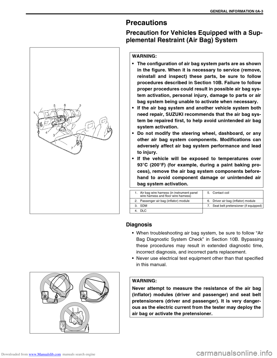
The configuration of air bag system parts are as shown
in the figure. When it is necessary to service (remove,
reinstall and inspect) these parts, be sure to follow
procedures described in Section 10B. Failure to follow
proper procedures could result in possible air bag sys-
tem activation, personal injury, damage to parts or air
bag system being unable to activate when necessary.
If the air bag system and another vehicle system both
need repair, SUZUKI recommends that the air bag sys-
tem be repaired first, to help avoid unintended air bag
system activation.
Do not modify the steering wheel, dashboard, or any
other air bag system components. Modifications can
adversely affect air bag system performance and lead
to injury.
If the vehicle will be exposed to temperatures over
93°C (200°F) (for example, during a paint baking pro-
cess), remove the air bag system components before-
hand to avoid component damage or unintended air
bag system activation.
1. Air bag wire harness (in instrument panel
wire harness and floor wire harness)5. Contact coil
2. Passenger air bag (inflator) module 6. Driver air bag (inflator) module
3. SDM 7. Seat belt pretensioner (if equipped)
4. DLC
WARNING:
Never attempt to measure the resistance of the air bag
(inflator) modules (driver and passenger) and seat belt
pretensioners (driver and passenger). It is very danger-
ous as the electric current from the tester may deploy the
air bag or activate the pretensioner.
Page 11 of 687

Downloaded from www.Manualslib.com manuals search engine 0A-6 GENERAL INFORMATION
CAUTION:
Even when the accident was light enough not to cause air bags to activate, be sure to inspect sys-
tem parts and other related parts according to instructions under “Repair and Inspection Required
after an Accident” in Section 10B.
When servicing parts other than air bag system, if shocks may be applied to air bag system compo-
nent parts, remove those parts beforehand.
When handling the air bag (inflator) modules (driver and passenger), seat belt pretensioners (driver
and passenger) or SDM, be careful not to drop it or apply an impact to it. If an excessive impact was
applied (e.g., dropped from a height of 90 cm (3 feet) or more), never attempt disassembly or repair
but replace it with a new one.
When grease, cleaning agent, oil, water, etc. has got onto air bag (inflator) modules (driver and pas-
senger) or seat belt pretensioners (drive and passenger), wipe off immediately with a dry cloth.
Air bag wire harness can be identified easily as it is covered with a yellow protection tube. Be very
careful when handling it.
When an open in air bag wire harness, damaged wire harness, connector or terminal is found,
replace wire harness, connectors and terminals as an assembly.
Do not apply power to the air bag system unless all components are connected or a diagnostic
chart requests it, as this will set a diagnostic trouble code.
Never use air bag system component parts from another vehicle.
When using electric welding, be sure to disconnect air bag (inflator) module connectors (driver and
passenger) and seat belt pretensioner connectors (driver and passenger) respectively.
Never expose air bag system component parts directly to hot air (drying or baking the vehicle after
painting) or flames.
WARNING / CAUTION labels are attached on each part of air bag system components. Be sure to
follow the instructions.
After vehicle is completely repaired, perform “Air Bag Diagnostic System Check” in Section 10B.
Page 14 of 687
Downloaded from www.Manualslib.com manuals search engine GENERAL INFORMATION 0A-9
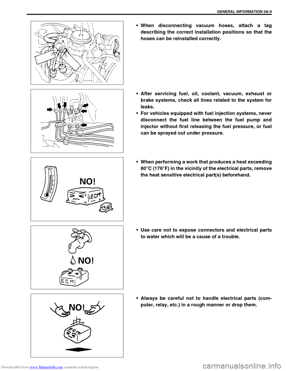
When disconnecting vacuum hoses, attach a tag
describing the correct installation positions so that the
hoses can be reinstalled correctly.
After servicing fuel, oil, coolant, vacuum, exhaust or
brake systems, check all lines related to the system for
leaks.
For vehicles equipped with fuel injection systems, never
disconnect the fuel line between the fuel pump and
injector without first releasing the fuel pressure, or fuel
can be sprayed out under pressure.
When performing a work that produces a heat exceeding
80°C (176°F) in the vicinity of the electrical parts, remove
the heat sensitive electrical part(s) beforehand.
Use care not to expose connectors and electrical parts
to water which will be a cause of a trouble.
Always be careful not to handle electrical parts (com-
puter, relay, etc.) in a rough manner or drop them.
Page 15 of 687
Downloaded from www.Manualslib.com manuals search engine 0A-10 GENERAL INFORMATION
Precautions For Catalytic Converter
For vehicles equipped with a catalytic converter, use only unleaded gasoline and be careful not to let a
large amount of unburned gasoline enter the converter or it can be damaged.
Conduct a spark jump test only when necessary, make it as short as possible, and do not open the
throttle.
Conduct engine compression checks within the shortest possible time.
Avoid situations which can result in engine misfire (e.g. starting the engine when the fuel tank is
nearly empty.)
Precautions For Electrical Circuit Service
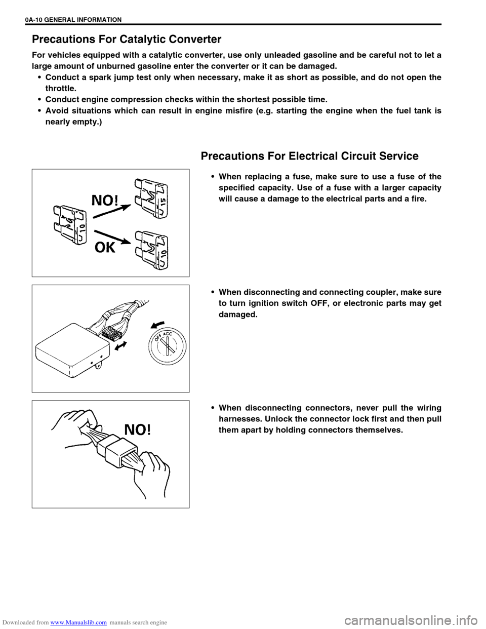
When replacing a fuse, make sure to use a fuse of the
specified capacity. Use of a fuse with a larger capacity
will cause a damage to the electrical parts and a fire.
When disconnecting and connecting coupler, make sure
to turn ignition switch OFF, or electronic parts may get
damaged.
When disconnecting connectors, never pull the wiring
harnesses. Unlock the connector lock first and then pull
them apart by holding connectors themselves.
Page 17 of 687
Downloaded from www.Manualslib.com manuals search engine 0A-12 GENERAL INFORMATION
Never connect any tester (voltmeter, ohmmeter, or what-
ever) to electronic control unit when its coupler is dis-
connected. Attempt to do it may cause damage to it.
Never connect an ohmmeter to electronic control unit
with its coupler connected to it. Attempt to do it may
cause damage to electronic control unit and sensors.
Be sure to use a specified voltmeter / ohmmeter. Other-
wise, accurate measurements may not be obtained or
personal injury may result.
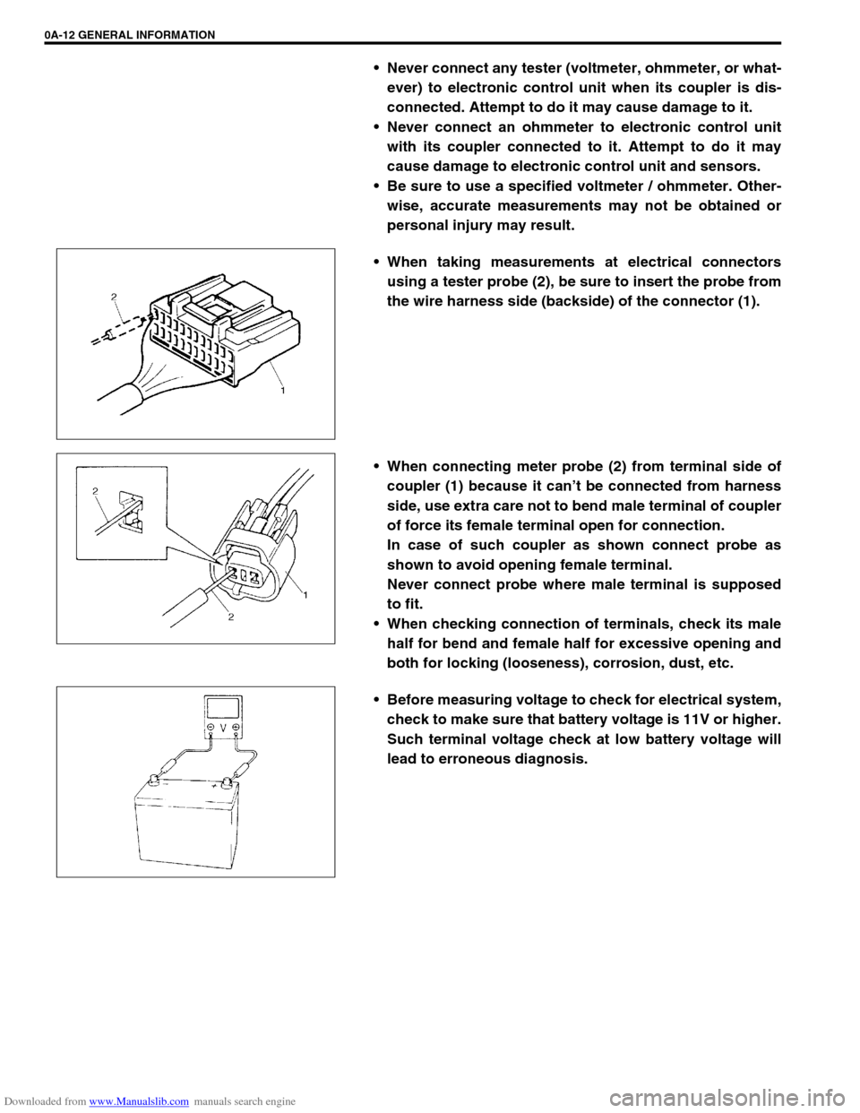
When taking measurements at electrical connectors
using a tester probe (2), be sure to insert the probe from
the wire harness side (backside) of the connector (1).
When connecting meter probe (2) from terminal side of
coupler (1) because it can’t be connected from harness
side, use extra care not to bend male terminal of coupler
of force its female terminal open for connection.
In case of such coupler as shown connect probe as
shown to avoid opening female terminal.
Never connect probe where male terminal is supposed
to fit.
When checking connection of terminals, check its male
half for bend and female half for excessive opening and
both for locking (looseness), corrosion, dust, etc.
Before measuring voltage to check for electrical system,
check to make sure that battery voltage is 11V or higher.
Such terminal voltage check at low battery voltage will
lead to erroneous diagnosis.
Page 18 of 687
Downloaded from www.Manualslib.com manuals search engine GENERAL INFORMATION 0A-13
Electrical Circuit Inspection Procedure
While there are various electrical circuit inspection methods,
described here is a general method to check its open and short
circuit by using an ohmmeter and a voltmeter.
Open circuit check
Possible causes for the open circuit are as follows. As the cause
is in the connector or terminal in many cases, they need to be
checked particularly carefully.
Loose connection of connector
Poor contact of terminal (due to dirt, corrosion or rust on it,
poor contact tension, entry of foreign object etc.)
Wire harness being open
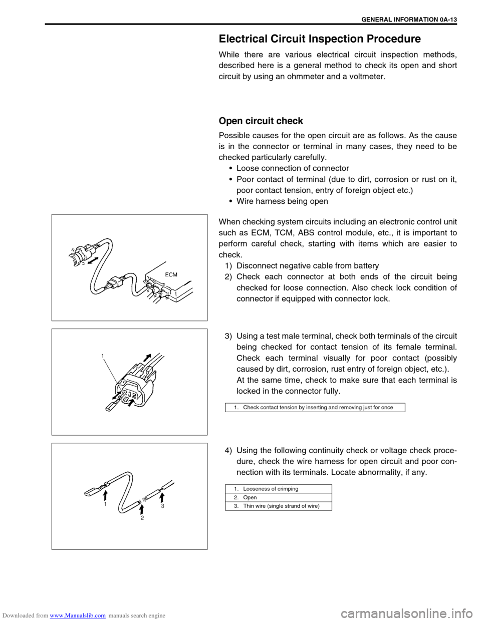
When checking system circuits including an electronic control unit
such as ECM, TCM, ABS control module, etc., it is important to
perform careful check, starting with items which are easier to
check.
1) Disconnect negative cable from battery
2) Check each connector at both ends of the circuit being
checked for loose connection. Also check lock condition of
connector if equipped with connector lock.
3) Using a test male terminal, check both terminals of the circuit
being checked for contact tension of its female terminal.
Check each terminal visually for poor contact (possibly
caused by dirt, corrosion, rust entry of foreign object, etc.).
At the same time, check to make sure that each terminal is
locked in the connector fully.
4) Using the following continuity check or voltage check proce-
dure, check the wire harness for open circuit and poor con-
nection with its terminals. Locate abnormality, if any.
1. Check contact tension by inserting and removing just for once
1. Looseness of crimping
2. Open
3. Thin wire (single strand of wire)
Page 19 of 687

Downloaded from www.Manualslib.com manuals search engine 0A-14 GENERAL INFORMATION
CONTINUITY CHECK
1) Measure resistance between connector terminals at both
ends of the circuit being checked (between A-1 and C-1 in
the figure).
If no continuity is indicated (infinity or over limit), that means
that the circuit is open between terminals A-1 and C-1.
2) Disconnect the connector included in the circuit (connector-B
in the figure) and measure resistance between terminals A-1
and B-1.
If no continuity is indicated, that means that the circuit is
open between terminals A-1 and B-1. If continuity is indi-
cated, there is an open circuit between terminals B-1 and C-
1 or an abnormality in connector-B.
VOLTAGE CHECK
If voltage is supplied to the circuit being checked, voltage check
can be used as circuit check.
1) With all connectors connected and voltage applied to the cir-
cuit being checked, measure voltage between each terminal
and body ground.
a) If measurements were taken as shown in the figure at the
left and results were as listed below, it means that the cir-
cuit is open between terminals B-1 and A-1.
Voltage Between
C-1 and body ground: Approx. 5V
B-1 and body ground: Approx. 5V
A-1 and body ground: 0V
b) Also, if measured values were as listed below, it means that
there is a resistance (abnormality) of such level that corre-
sponds to the voltage drop in the circuit between terminals
A-1 and B-1.
Voltage Between
C-1 and body ground: Approx. 5V
B-1 and body ground: Approx. 5V
A-1 and body ground: Approx. 3V (2V voltage drop)
Page 20 of 687
Downloaded from www.Manualslib.com manuals search engine GENERAL INFORMATION 0A-15
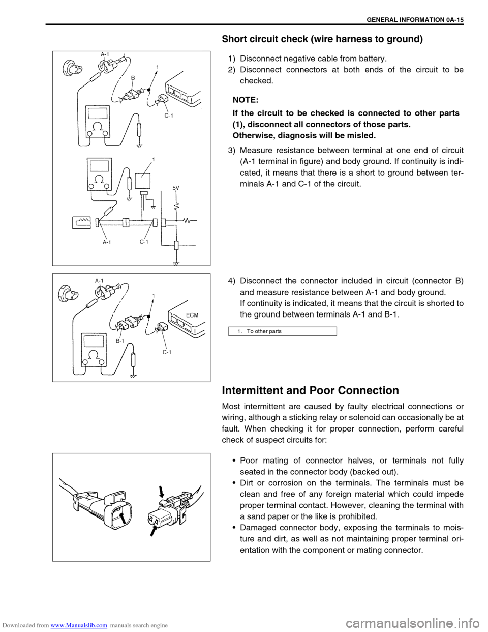
Short circuit check (wire harness to ground)
1) Disconnect negative cable from battery.
2) Disconnect connectors at both ends of the circuit to be
checked.
3) Measure resistance between terminal at one end of circuit
(A-1 terminal in figure) and body ground. If continuity is indi-
cated, it means that there is a short to ground between ter-
minals A-1 and C-1 of the circuit.
4) Disconnect the connector included in circuit (connector B)
and measure resistance between A-1 and body ground.
If continuity is indicated, it means that the circuit is shorted to
the ground between terminals A-1 and B-1.
Intermittent and Poor Connection
Most intermittent are caused by faulty electrical connections or
wiring, although a sticking relay or solenoid can occasionally be at
fault. When checking it for proper connection, perform careful
check of suspect circuits for:
Poor mating of connector halves, or terminals not fully
seated in the connector body (backed out).
Dirt or corrosion on the terminals. The terminals must be
clean and free of any foreign material which could impede
proper terminal contact. However, cleaning the terminal with
a sand paper or the like is prohibited.
Damaged connector body, exposing the terminals to mois-
ture and dirt, as well as not maintaining proper terminal ori-
entation with the component or mating connector. NOTE:
If the circuit to be checked is connected to other parts
(1), disconnect all connectors of those parts.
Otherwise, diagnosis will be misled.
1. To other parts
Page 21 of 687
Downloaded from www.Manualslib.com manuals search engine 0A-16 GENERAL INFORMATION
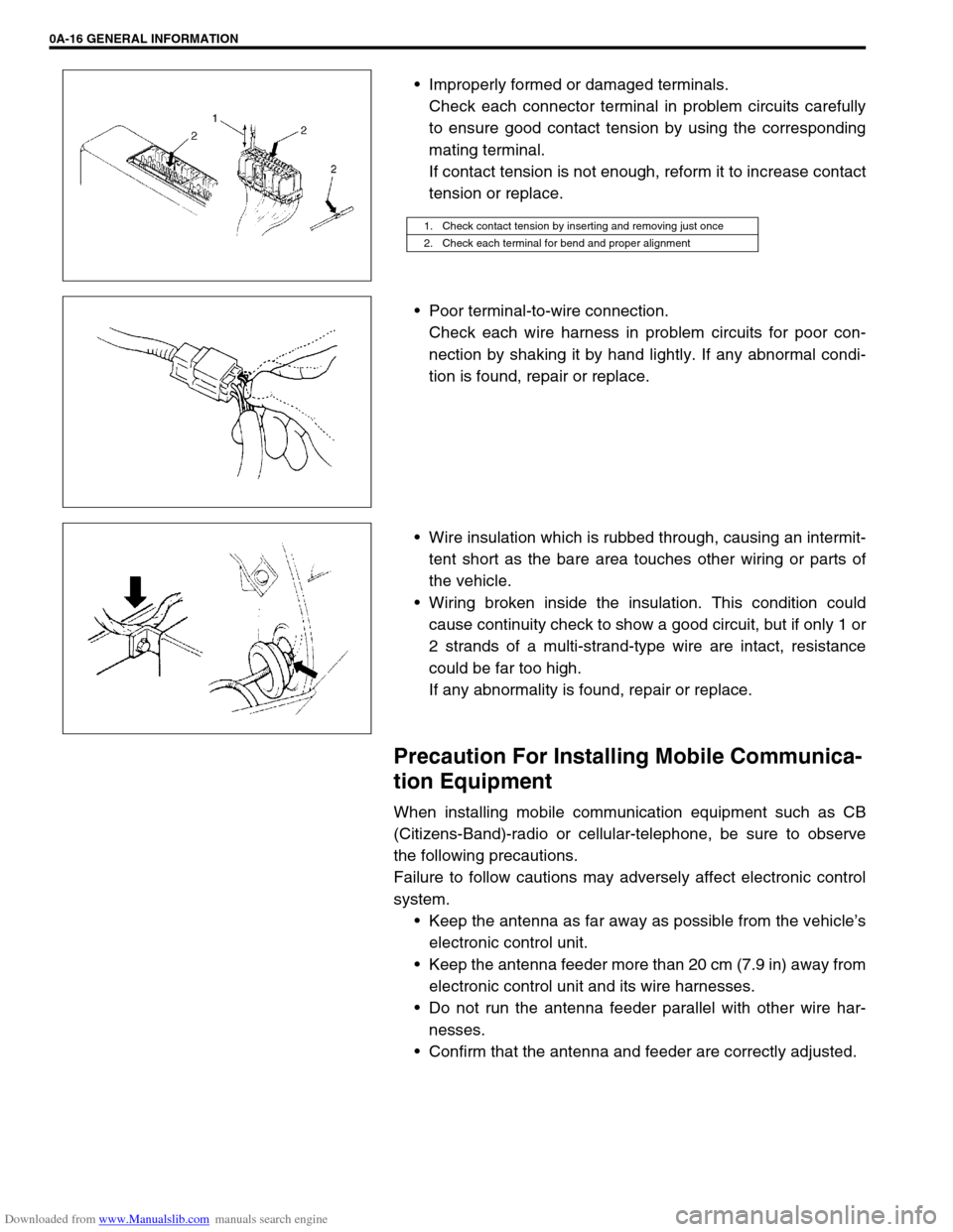
Improperly formed or damaged terminals.
Check each connector terminal in problem circuits carefully
to ensure good contact tension by using the corresponding
mating terminal.
If contact tension is not enough, reform it to increase contact
tension or replace.
Poor terminal-to-wire connection.
Check each wire harness in problem circuits for poor con-
nection by shaking it by hand lightly. If any abnormal condi-
tion is found, repair or replace.
Wire insulation which is rubbed through, causing an intermit-
tent short as the bare area touches other wiring or parts of
the vehicle.
Wiring broken inside the insulation. This condition could
cause continuity check to show a good circuit, but if only 1 or
2 strands of a multi-strand-type wire are intact, resistance
could be far too high.
If any abnormality is found, repair or replace.
Precaution For Installing Mobile Communica-
tion Equipment
When installing mobile communication equipment such as CB
(Citizens-Band)-radio or cellular-telephone, be sure to observe
the following precautions.
Failure to follow cautions may adversely affect electronic control
system.
Keep the antenna as far away as possible from the vehicle’s
electronic control unit.
Keep the antenna feeder more than 20 cm (7.9 in) away from
electronic control unit and its wire harnesses.
Do not run the antenna feeder parallel with other wire har-
nesses.
Confirm that the antenna and feeder are correctly adjusted.
1. Check contact tension by inserting and removing just once
2. Check each terminal for bend and proper alignment