Bleed SUZUKI JIMNY 2005 3.G Service Owner's Guide
[x] Cancel search | Manufacturer: SUZUKI, Model Year: 2005, Model line: JIMNY, Model: SUZUKI JIMNY 2005 3.GPages: 687, PDF Size: 13.38 MB
Page 305 of 687
Downloaded from www.Manualslib.com manuals search engine 5-44 BRAKES
P (Proportioning) Valve
REMOVAL
1) Clean around reservoir cap and take out fluid with syringe or
such.
2) Disconnect brake pipes from P valve.
3) Remove P valve.
INSTALLATION
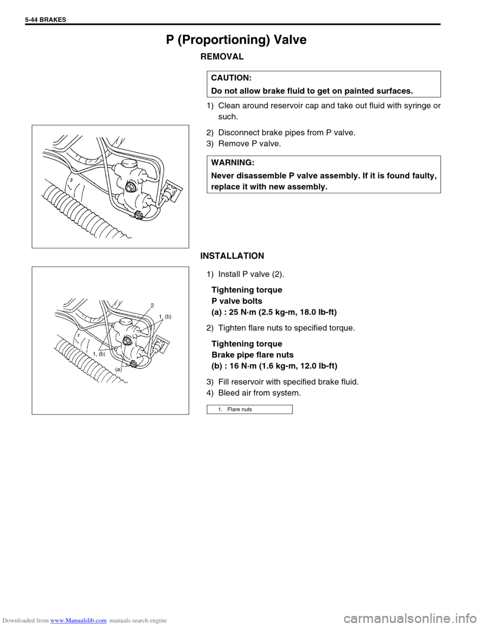
1) Install P valve (2).
Tightening torque
P valve bolts
(a) : 25 N·m (2.5 kg-m, 18.0 lb-ft)
2) Tighten flare nuts to specified torque.
Tightening torque
Brake pipe flare nuts
(b) : 16 N·m (1.6 kg-m, 12.0 lb-ft)
3) Fill reservoir with specified brake fluid.
4) Bleed air from system.CAUTION:
Do not allow brake fluid to get on painted surfaces.
WARNING:
Never disassemble P valve assembly. If it is found faulty,
replace it with new assembly.
1. Flare nuts
Page 311 of 687

Downloaded from www.Manualslib.com manuals search engine 5-50 BRAKES
REMOVAL
1) Raise, suitably support vehicle. Remove wheel if necessary.
2) Clean dirt and foreign material from both hose end or pipe end fittings. Remove brake hose and pipe.
INSTALLATION
1) Install brake hose and pipe by reversing removal procedure, noting the following points.
For installation, make sure that steering wheel is in straightforward position and hose has no twist or kink.
Check to make sure that hose doesn’t contact any part of suspension, both in extreme right and extreme left
turn conditions. If it does at any point, remove and correct. Fill and maintain brake fluid level in reservoir.
Bleed brake system.
2) Perform brake test and check installed part for fluid leakage.
Page 312 of 687
Downloaded from www.Manualslib.com manuals search engine BRAKES 5-51
Rear Brake Hose/Pipe
REMOVAL
1) Raise, suitably support vehicle. Remove wheel if necessary.
2) Clean dirt and foreign material from both hose end or pipe end fittings. Remove brake hose and pipe.
INSTALLATION
1) Install brake hose and pipe by reversing removal procedure, noting the following points.
Fill and maintain brake fluid level in reservoir. Bleed brake system.
2) Perform brake test and check each installed part for fluid leakage.
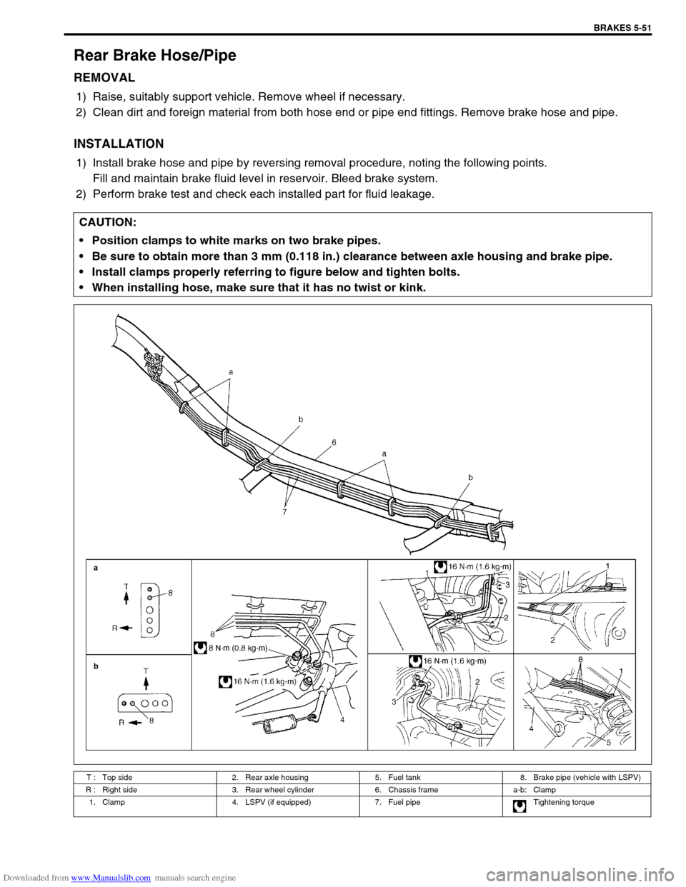
CAUTION:
Position clamps to white marks on two brake pipes.
Be sure to obtain more than 3 mm (0.118 in.) clearance between axle housing and brake pipe.
Install clamps properly referring to figure below and tighten bolts.
When installing hose, make sure that it has no twist or kink.
T : Top side 2. Rear axle housing 5. Fuel tank 8. Brake pipe (vehicle with LSPV)
R : Right side 3. Rear wheel cylinder 6. Chassis frame a-b: Clamp
1. Clamp 4. LSPV (if equipped) 7. Fuel pipe Tightening torque
Page 315 of 687

Downloaded from www.Manualslib.com manuals search engine 5-54 BRAKES
Tightening Torque Specifications
Required Service Material
Fastening partTightening torque
Nm kg-m lb-ft
Brake caliper carrier bolt 85 8.5 61.5
Brake caliper pin bolt 22 2.2 16.0
Front brake flexible hose bolt 23 2.3 17.0
Rear brake back plate nut 23 2.3 17.0
Master cylinder nut 13 1.3 9.5
Booster nut 13 1.3 9.5
Brake pipe 5-way 4-way joint bolt 11 1.1 8.0
Brake pipe flare nut 16 1.6 12.0
LSPV bolt/P valve bolt 25 2.5 18.0
Brake bleeder plugFront caliper 11 1.1 8.0
Rear wheel cylinder, LSPV 8 0.8 6.0
Wheel nut 95 9.5 69.0
Hose bracket bolt 11 1.1 8.0
Booster clevis nut 25 2.5 18.0
Stop light switch lock nut 6.5 0.65 4.7
Parking brake lever bolt 23 2.3 17.0
Wheel cylinder mounting bolt 9 0.9 6.5
Piston stopper bolt 10 1.0 7.5
LSPV adjust bolt 25 2.5 18.0
Material Recommended SUZUKI products Use
Brake fluid Indicated on reservoir tank cap or
described in owner’s manual of vehi-
cleTo fill master cylinder reservoir.
To clean and apply to inner parts of master
cylinder caliper and wheel cylinder when they
are disassembled.
Water tight sealant SEALING COMPOUND 366E
99000-31090To apply to mating surfaces of brake back
plate and rear wheel cylinder.
Sealant SUZUKI BOND NO. 1215
99000-31110To apply to mating surfaces of brake back
plate and rear axle housing.
To apply to mating surfaces of brake back
plate and rear wheel bearing retainer.
Page 347 of 687
Downloaded from www.Manualslib.com manuals search engine 5E-30 ANTILOCK BRAKE SYSTEM (ABS)
ABS Hydraulic Unit / Control Module Assembly
HYDRAULIC UNIT INSPECTION
Check hydraulic unit for fluid leakage.
If any, repair or replace.
REMOVAL
1) Disconnect negative cable at battery.
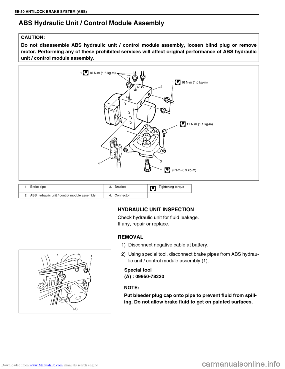
2) Using special tool, disconnect brake pipes from ABS hydrau-
lic unit / control module assembly (1).
Special tool
(A) : 09950-78220 CAUTION:
Do not disassemble ABS hydraulic unit / control module assembly, loosen blind plug or remove
motor. Performing any of these prohibited services will affect original performance of ABS hydraulic
unit / control module assembly.
1. Brake pipe 3. Bracket Tightening torque
2. ABS hydraulic unit / control module assembly 4. Connector
NOTE:
Put bleeder plug cap onto pipe to prevent fluid from spill-
ing. Do not allow brake fluid to get on painted surfaces.
Page 348 of 687
Downloaded from www.Manualslib.com manuals search engine ANTILOCK BRAKE SYSTEM (ABS) 5E-31
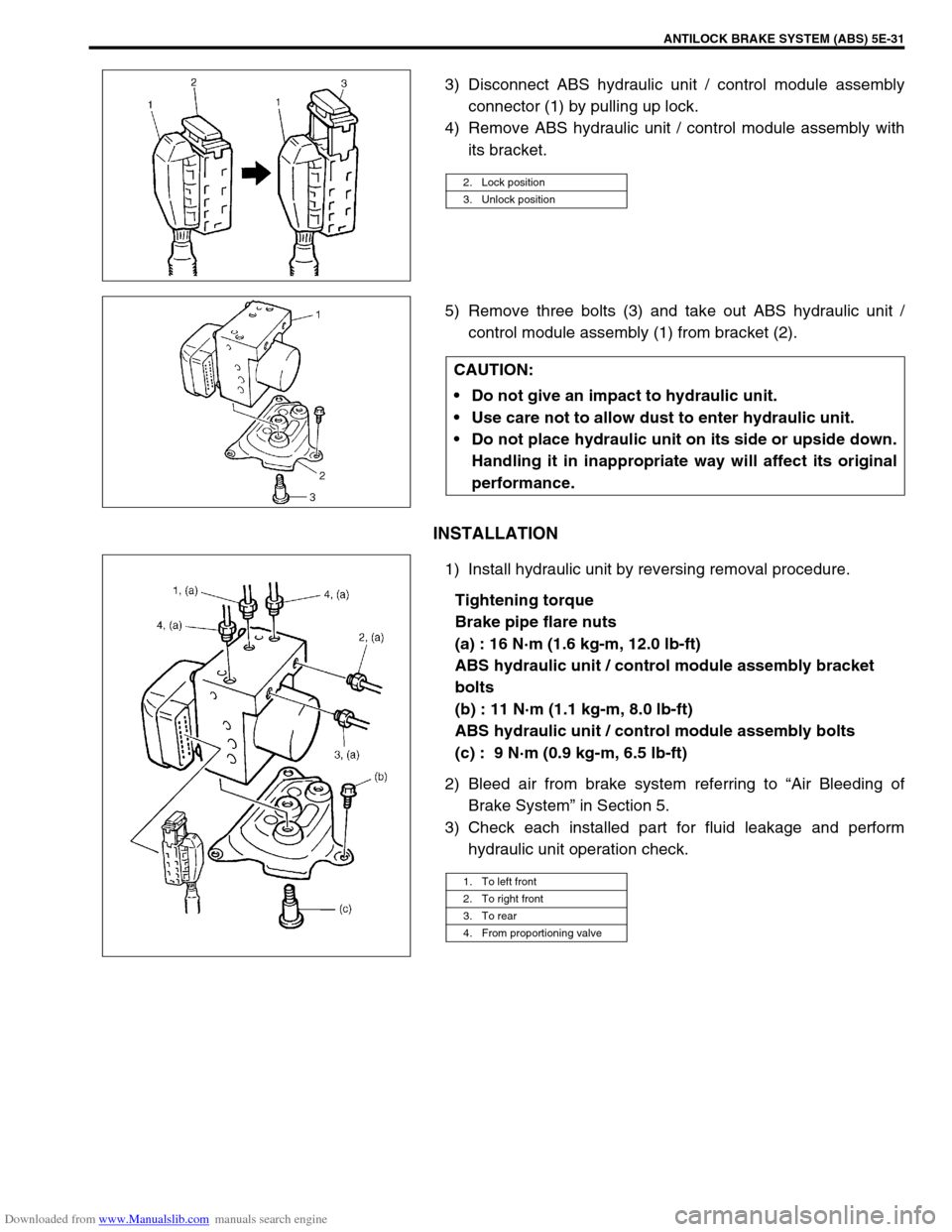
3) Disconnect ABS hydraulic unit / control module assembly
connector (1) by pulling up lock.
4) Remove ABS hydraulic unit / control module assembly with
its bracket.
5) Remove three bolts (3) and take out ABS hydraulic unit /
control module assembly (1) from bracket (2).
INSTALLATION
1) Install hydraulic unit by reversing removal procedure.
Tightening torque
Brake pipe flare nuts
(a) : 16 N·m (1.6 kg-m, 12.0 lb-ft)
ABS hydraulic unit / control module assembly bracket
bolts
(b) : 11 N·m (1.1 kg-m, 8.0 lb-ft)
ABS hydraulic unit / control module assembly bolts
(c) : 9 N·m (0.9 kg-m, 6.5 lb-ft)
2) Bleed air from brake system referring to “Air Bleeding of
Brake System” in Section 5.
3) Check each installed part for fluid leakage and perform
hydraulic unit operation check.
2. Lock position
3. Unlock position
CAUTION:
Do not give an impact to hydraulic unit.
Use care not to allow dust to enter hydraulic unit.
Do not place hydraulic unit on its side or upside down.
Handling it in inappropriate way will affect its original
performance.
1. To left front
2. To right front
3. To rear
4. From proportioning valve
Page 580 of 687
Downloaded from www.Manualslib.com manuals search engine ENGINE COOLING 6B-3
Radiator Cap
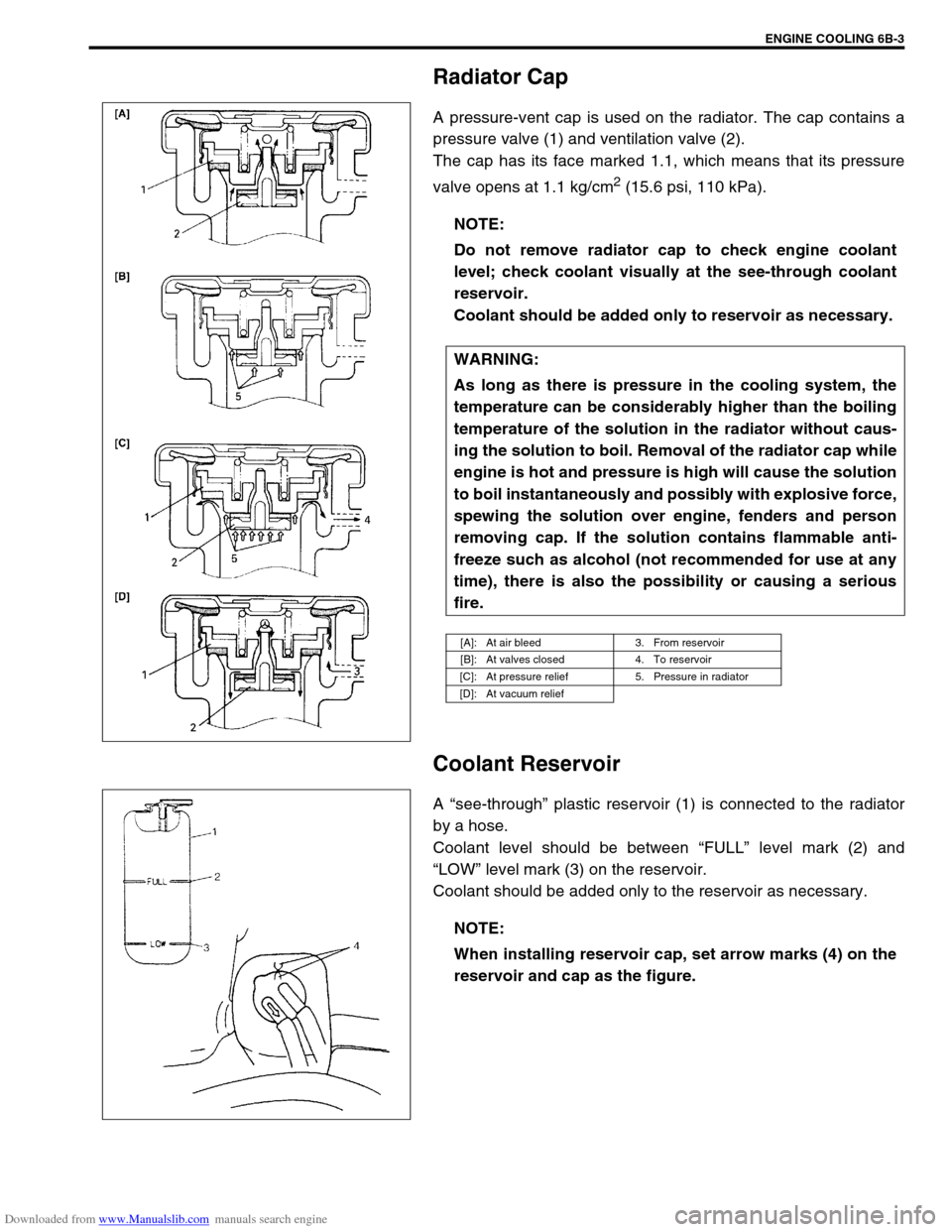
A pressure-vent cap is used on the radiator. The cap contains a
pressure valve (1) and ventilation valve (2).
The cap has its face marked 1.1, which means that its pressure
valve opens at 1.1 kg/cm
2 (15.6 psi, 110 kPa).
Coolant Reservoir
A “see-through” plastic reservoir (1) is connected to the radiator
by a hose.
Coolant level should be between “FULL” level mark (2) and
“LOW” level mark (3) on the reservoir.
Coolant should be added only to the reservoir as necessary.NOTE:
Do not remove radiator cap to check engine coolant
level; check coolant visually at the see-through coolant
reservoir.
Coolant should be added only to reservoir as necessary.
WARNING:
As long as there is pressure in the cooling system, the
temperature can be considerably higher than the boiling
temperature of the solution in the radiator without caus-
ing the solution to boil. Removal of the radiator cap while
engine is hot and pressure is high will cause the solution
to boil instantaneously and possibly with explosive force,
spewing the solution over engine, fenders and person
removing cap. If the solution contains flammable anti-
freeze such as alcohol (not recommended for use at any
time), there is also the possibility or causing a serious
fire.
[A]: At air bleed 3. From reservoir
[B]: At valves closed 4. To reservoir
[C]: At pressure relief 5. Pressure in radiator
[D]: At vacuum relief
NOTE:
When installing reservoir cap, set arrow marks (4) on the
reservoir and cap as the figure.
Page 581 of 687
Downloaded from www.Manualslib.com manuals search engine 6B-4 ENGINE COOLING
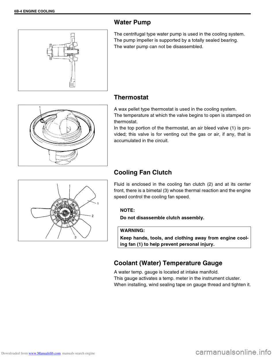
Water Pump
The centrifugal type water pump is used in the cooling system.
The pump impeller is supported by a totally sealed bearing.
The water pump can not be disassembled.
Thermostat
A wax pellet type thermostat is used in the cooling system.
The temperature at which the valve begins to open is stamped on
thermostat.
In the top portion of the thermostat, an air bleed valve (1) is pro-
vided; this valve is for venting out the gas or air, if any, that is
accumulated in the circuit.
Cooling Fan Clutch
Fluid is enclosed in the cooling fan clutch (2) and at its center
front, there is a bimetal (3) whose thermal reaction and the engine
speed control the cooling fan speed.
Coolant (Water) Temperature Gauge
A water temp. gauge is located at intake manifold.
This gauge activates a temp. meter in the instrument cluster.
When installing, wind sealing tape on gauge thread and tighten it.
NOTE:
Do not disassemble clutch assembly.
WARNING:
Keep hands, tools, and clothing away from engine cool-
ing fan (1) to help prevent personal injury.
Page 589 of 687
Downloaded from www.Manualslib.com manuals search engine 6B-12 ENGINE COOLING
INSPECTION
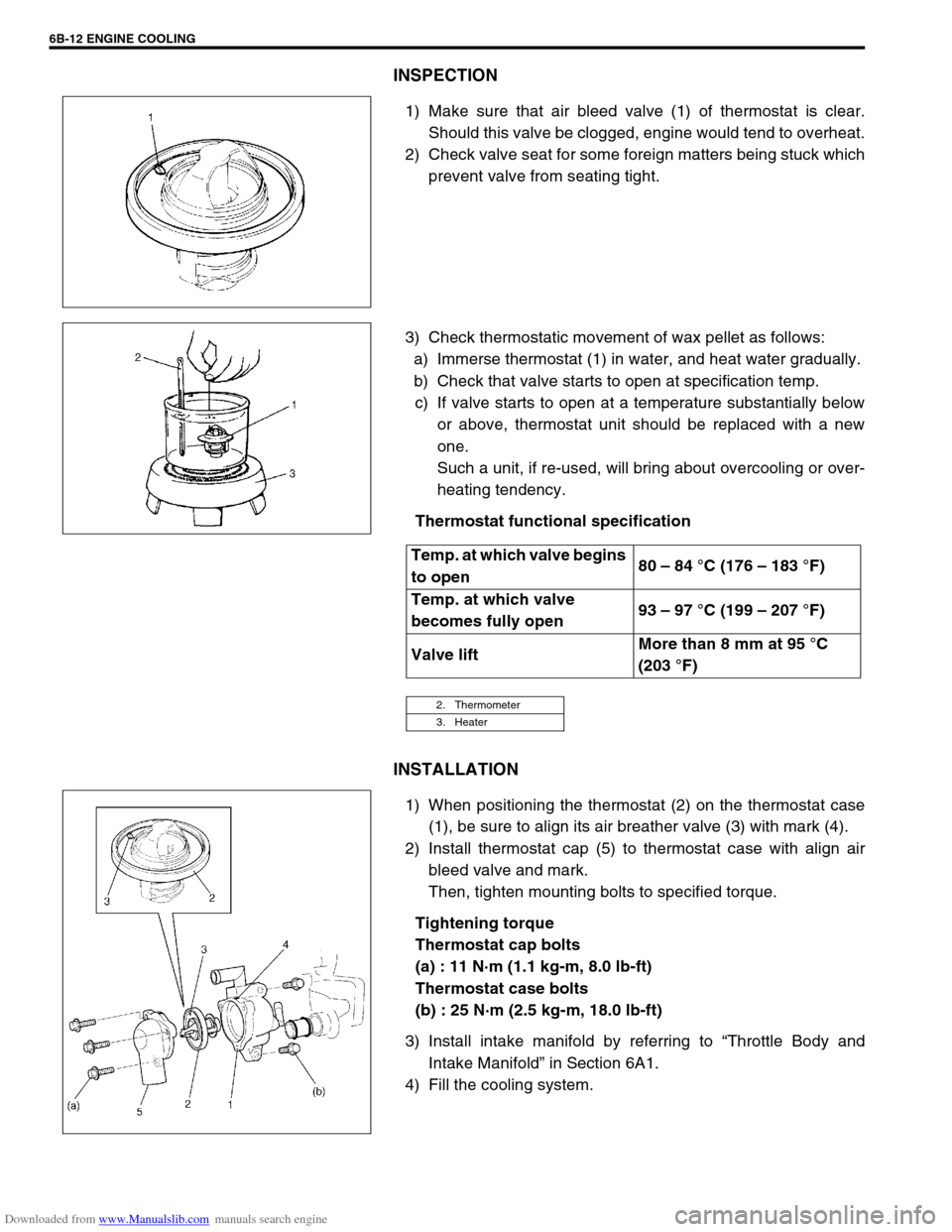
1) Make sure that air bleed valve (1) of thermostat is clear.
Should this valve be clogged, engine would tend to overheat.
2) Check valve seat for some foreign matters being stuck which
prevent valve from seating tight.
3) Check thermostatic movement of wax pellet as follows:
a) Immerse thermostat (1) in water, and heat water gradually.
b) Check that valve starts to open at specification temp.
c) If valve starts to open at a temperature substantially below
or above, thermostat unit should be replaced with a new
one.
Such a unit, if re-used, will bring about overcooling or over-
heating tendency.
Thermostat functional specification
INSTALLATION
1) When positioning the thermostat (2) on the thermostat case
(1), be sure to align its air breather valve (3) with mark (4).
2) Install thermostat cap (5) to thermostat case with align air
bleed valve and mark.
Then, tighten mounting bolts to specified torque.
Tightening torque
Thermostat cap bolts
(a) : 11 N·m (1.1 kg-m, 8.0 lb-ft)
Thermostat case bolts
(b) : 25 N·m (2.5 kg-m, 18.0 lb-ft)
3) Install intake manifold by referring to “Throttle Body and
Intake Manifold” in Section 6A1.
4) Fill the cooling system.
Temp. at which valve begins
to open80 – 84 °C (176 – 183 °F)
Temp. at which valve
becomes fully open93 – 97 °C (199 – 207 °F)
Valve liftMore than 8 mm at 95 °C
(203 °F)
2. Thermometer
3. Heater