Gear SUZUKI JIMNY 2005 3.G Service Owner's Guide
[x] Cancel search | Manufacturer: SUZUKI, Model Year: 2005, Model line: JIMNY, Model: SUZUKI JIMNY 2005 3.GPages: 687, PDF Size: 13.38 MB
Page 165 of 687
Downloaded from www.Manualslib.com manuals search engine 3C-12 STEERING WHEEL AND COLUMN
REMOVAL
1) Disconnect negative battery cable at battery terminal.
2) For vehicle equipped with air bag system, disable air bag
system referring to “Disabling Air Bag System” in Section
10B.
3) If necessary, remove steering wheel and combination switch
assembly referring to “Steering Wheel” and “Combination
switch/Contact Coil and Combination Switch Assembly” in
this section.
If not removing steering wheel and/or combination switch
assembly, perform the following procedure.
a) Turn steering wheel so that vehicle’s front tires are at
straight ahead position.
b) Turn ignition switch to “LOCK” position and remove key.
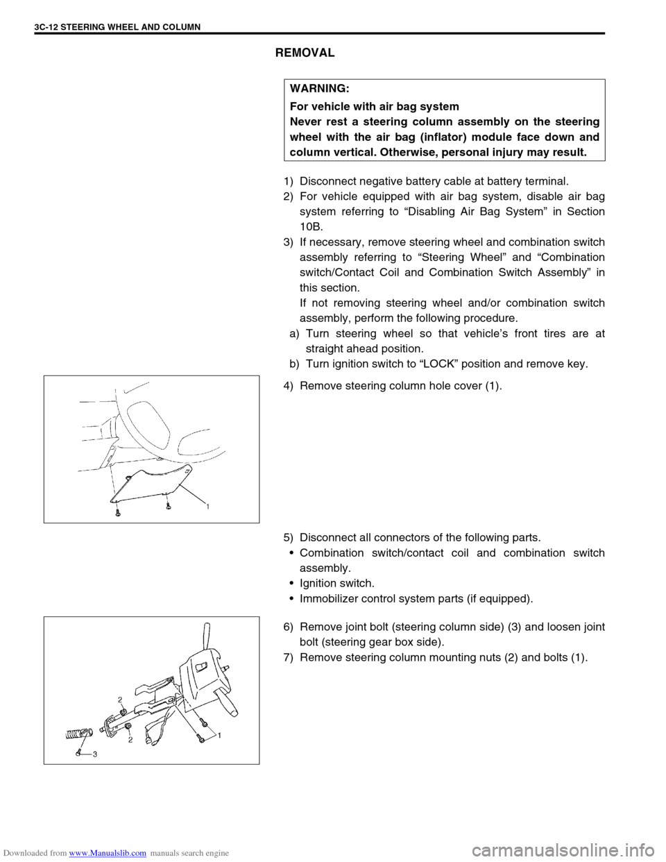
4) Remove steering column hole cover (1).
5) Disconnect all connectors of the following parts.
Combination switch/contact coil and combination switch
assembly.
Ignition switch.
Immobilizer control system parts (if equipped).
6) Remove joint bolt (steering column side) (3) and loosen joint
bolt (steering gear box side).
7) Remove steering column mounting nuts (2) and bolts (1).WARNING:
For vehicle with air bag system
Never rest a steering column assembly on the steering
wheel with the air bag (inflator) module face down and
column vertical. Otherwise, personal injury may result.
Page 168 of 687
Downloaded from www.Manualslib.com manuals search engine STEERING WHEEL AND COLUMN 3C-15
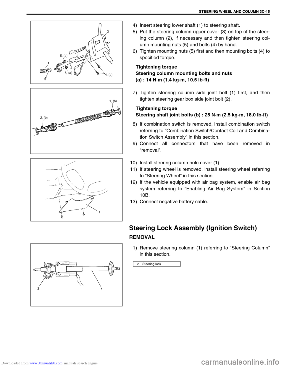
4) Insert steering lower shaft (1) to steering shaft.
5) Put the steering column upper cover (3) on top of the steer-
ing column (2), if necessary and then tighten steering col-
umn mounting nuts (5) and bolts (4) by hand.
6) Tighten mounting nuts (5) first and then mounting bolts (4) to
specified torque.
Tightening torque
Steering column mounting bolts and nuts
(a) : 14 N·m (1.4 kg-m, 10.5 lb-ft)
7) Tighten steering column side joint bolt (1) first, and then
tighten steering gear box side joint bolt (2).
Tightening torque
Steering shaft joint bolts (b) : 25 N·m (2.5 kg-m, 18.0 lb-ft)
8) If combination switch is removed, install combination switch
referring to “Combination Switch/Contact Coil and Combina-
tion Switch Assembly” in this section.
9) Connect all connectors that have been removed in
“removal”.
10) Install steering column hole cover (1).
11) If steering wheel is removed, install steering wheel referring
to “Steering Wheel” in this section.
12) If the vehicle equipped with air bag system, enable air bag
system referring to “Enabling Air Bag System” in Section
10B.
13) Connect negative battery cable.
Steering Lock Assembly (Ignition Switch)
REMOVAL
1) Remove steering column (1) referring to “Steering Column”
in this section.
2. Steering lock
Page 170 of 687
Downloaded from www.Manualslib.com manuals search engine STEERING WHEEL AND COLUMN 3C-17
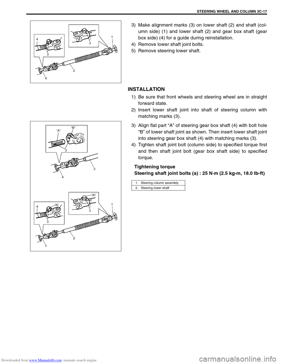
3) Make alignment marks (3) on lower shaft (2) and shaft (col-
umn side) (1) and lower shaft (2) and gear box shaft (gear
box side) (4) for a guide during reinstallation.
4) Remove lower shaft joint bolts.
5) Remove steering lower shaft.
INSTALLATION
1) Be sure that front wheels and steering wheel are in straight
forward state.
2) Insert lower shaft joint into shaft of steering column with
matching marks (3).
3) Align flat part “A” of steering gear box shaft (4) with bolt hole
“B” of lower shaft joint as shown. Then insert lower shaft joint
into steering gear box shaft (4) with matching marks (3).
4) Tighten shaft joint bolt (column side) to specified torque first
and then shaft joint bolt (gear box shaft side) to specified
torque.
Tightening torque
Steering shaft joint bolts (a) : 25 N·m (2.5 kg-m, 18.0 lb-ft)
1. Steering column assembly
2. Steering lower shaft
Page 178 of 687

Downloaded from www.Manualslib.com manuals search engine FRONT SUSPENSION 3D-5
Components and Functions
Component Function
4WD switch When the transfer shift lever is shifted to 4L or 4H position from 2H, this switch
turns ON and cause the 4WD control system to turn ON.
4WD controller When the 4WD switch turns on, the 4WD controller activates VSV2 to lock the
air locking hubs and when it receives an “ON” signal from the vacuum switch, it
makes VSV2 to complete operation within 5 seconds and causes the 4WD indi-
cator light to light up.
If vacuum in the vacuum circuit fails to reach the specified level due to a leakage
in the vacuum circuit (when no “ON” signal is inputted from the vacuum switch),
the 4WD controller stops operation of VSV2 in 15 seconds and makes the 4WD
indicator light to flash to warn occurrence of a trouble.
When the 4WD switch turns off, the 4WD controller activates VSV1 for 10 sec-
onds to unlock the hubs and at the same time makes the 4WD indicator light
turn off.
VSV1 VSV1 operates according to the signal from the 4WD controller. When it is acti-
vated, the port opens and vacuum in the intake manifold is applied through the
vacuum circuit to unlock to the slide gear in the air locking hub. As a result, the
air locking hubs are unlocked.
VSV2 VSV2 operates according to the signal from the 4WD controller. When it is acti-
vated, the port opens and vacuum in the intake manifold is applied through the
vacuum circuit to lock to the slide gear in the air locking hub. As a result, the air
locking hubs are locked.
Vacuum switch When VSV2 receives the “ON” signal from 4WD switch, vacuum is applied
through its circuit to the vacuum switch. The vacuum switch turns on when it
detects vacuum exceeding 260 mmHg.
“4WD” indicator lamp It lights up when 4WD control system is in the 4WD mode.
It flashes to warn that locking hub operation has not completed (4WD control
system fails to shift 4WD).
Page 179 of 687
Downloaded from www.Manualslib.com manuals search engine 3D-6 FRONT SUSPENSION
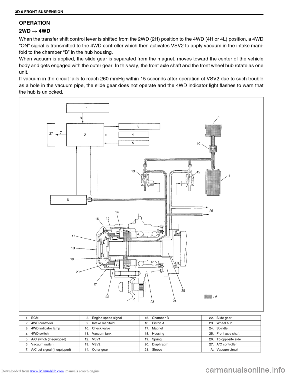
OPERATION
2WD
→ 4WD
When the transfer shift control lever is shifted from the 2WD (2H) position to the 4WD (4H or 4L) position, a 4WD
“ON” signal is transmitted to the 4WD controller which then activates VSV2 to apply vacuum in the intake mani-
fold to the chamber “B” in the hub housing.
When vacuum is applied, the slide gear is separated from the magnet, moves toward the center of the vehicle
body and gets engaged with the outer gear. In this way, the front axle shaft and the front wheel hub rotate as one
unit.
If vacuum in the circuit fails to reach 260 mmHg within 15 seconds after operation of VSV2 due to such trouble
as a hole in the vacuum pipe, the slide gear does not operate and the 4WD indicator light flashes to warn that
the hub is unlocked.
1. ECM 8. Engine speed signal 15. Chamber B 22. Slide gear
2. 4WD controller 9. Intake manifold 16. Piston A 23. Wheel hub
3. 4WD indicator lamp 10. Check valve 17. Magnet 24. Spindle
4.4WD switch 11. Vacuum tank 18. Housing 25. Front axle shaft
5. A/C switch (if equipped) 12. VSV1 19. Spring 26. To opposite side
6. Vacuum switch 13. VSV2 20. Diaphragm 27. A/C controller
7. A/C cut signal (if equipped) 14. Outer gear 21. Sleeve A: Vacuum circuit
Page 180 of 687
Downloaded from www.Manualslib.com manuals search engine FRONT SUSPENSION 3D-7
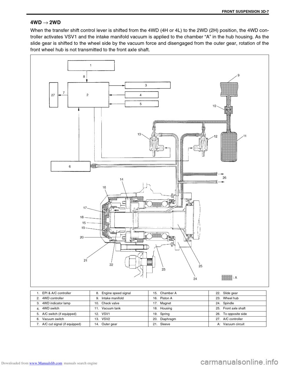
4WD
→ 2WD
When the transfer shift control lever is shifted from the 4WD (4H or 4L) to the 2WD (2H) position, the 4WD con-
troller activates VSV1 and the intake manifold vacuum is applied to the chamber “A” in the hub housing. As the
slide gear is shifted to the wheel side by the vacuum force and disengaged from the outer gear, rotation of the
front wheel hub is not transmitted to the front axle shaft.
1. EPI & A/C controller 8. Engine speed signal 15. Chamber A 22. Slide gear
2. 4WD controller 9. Intake manifold 16. Piston A 23. Wheel hub
3. 4WD indicator lamp 10. Check valve 17. Magnet 24. Spindle
4.4WD switch 11. Vacuum tank 18. Housing 25. Front axle shaft
5. A/C switch (if equipped) 12. VSV1 19. Spring 26. To opposite side
6. Vacuum switch 13. VSV2 20. Diaphragm 27. A/C controller
7. A/C cut signal (if equipped) 14. Outer gear 21. Sleeve A: Vacuum circuit
Page 205 of 687
Downloaded from www.Manualslib.com manuals search engine 3D-32 FRONT SUSPENSION
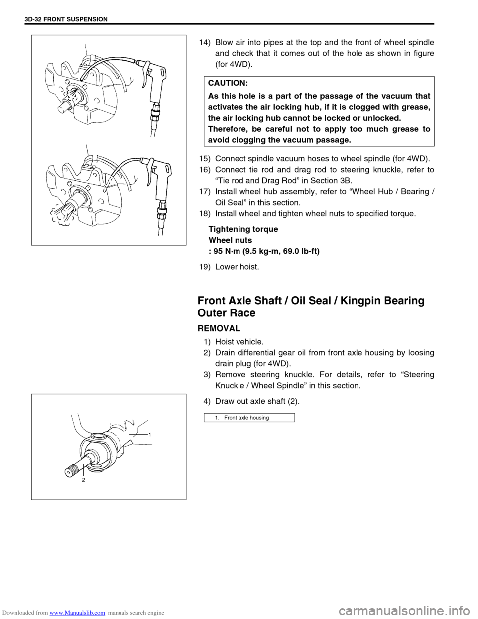
14) Blow air into pipes at the top and the front of wheel spindle
and check that it comes out of the hole as shown in figure
(for 4WD).
15) Connect spindle vacuum hoses to wheel spindle (for 4WD).
16) Connect tie rod and drag rod to steering knuckle, refer to
“Tie rod and Drag Rod” in Section 3B.
17) Install wheel hub assembly, refer to “Wheel Hub / Bearing /
Oil Seal” in this section.
18) Install wheel and tighten wheel nuts to specified torque.
Tightening torque
Wheel nuts
: 95 N·m (9.5 kg-m, 69.0 lb-ft)
19) Lower hoist.
Front Axle Shaft / Oil Seal / Kingpin Bearing
Outer Race
REMOVAL
1) Hoist vehicle.
2) Drain differential gear oil from front axle housing by loosing
drain plug (for 4WD).
3) Remove steering knuckle. For details, refer to “Steering
Knuckle / Wheel Spindle” in this section.
4) Draw out axle shaft (2).CAUTION:
As this hole is a part of the passage of the vacuum that
activates the air locking hub, if it is clogged with grease,
the air locking hub cannot be locked or unlocked.
Therefore, be careful not to apply too much grease to
avoid clogging the vacuum passage.
1. Front axle housing
Page 207 of 687

Downloaded from www.Manualslib.com manuals search engine 3D-34 FRONT SUSPENSION
4) Install axle shaft (2) to front axle housing (1) (for 4WD).
5) Install knuckle to front axle housing. For details, refer to
“Steering Knuckle / Wheel Spindle” in this section.
6) Refill front axle (differential) housing with new specified gear
oil (for 4WD). Refer to “Maintenance Service” in Section 7E
for refill.
7) After servicing, check that no oil leakage exists.
Steering Knuckle Seal
REMOVAL
1) Hoist vehicle.
2) Remove knuckle seal cover bolts and seal cover (1).
3) Cut oil seal in place with scissors or knife, and take it off.
INSTALLATION
1) Cut replacement oil seal at one place with scissors or a
knife.
Page 211 of 687
Downloaded from www.Manualslib.com manuals search engine 3D-38 FRONT SUSPENSION
Front Axle Housing
REMOVAL
1) Hoist vehicle.
2) Remove front wheels.
3) Drain front differential gear oil (for 4WD).
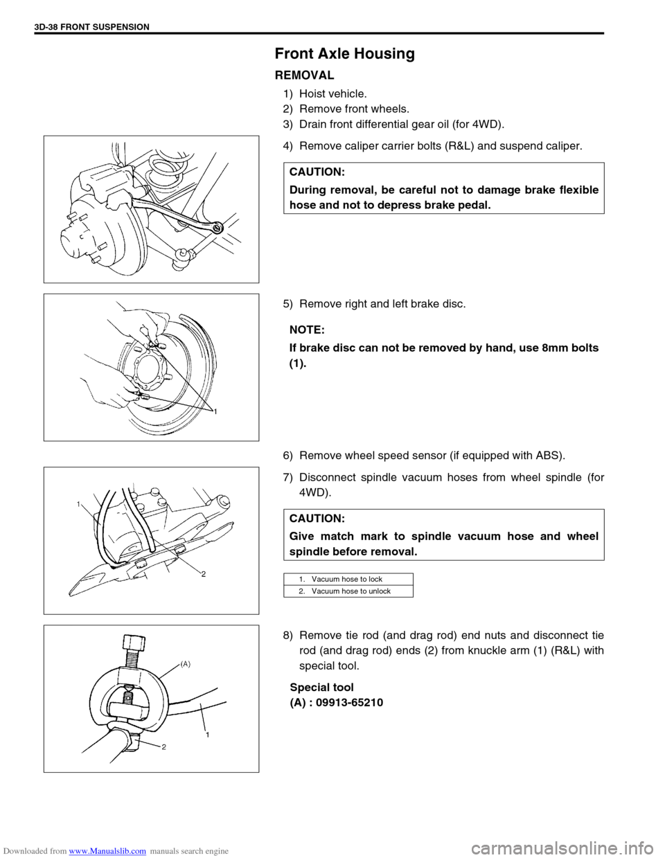
4) Remove caliper carrier bolts (R&L) and suspend caliper.
5) Remove right and left brake disc.
6) Remove wheel speed sensor (if equipped with ABS).
7) Disconnect spindle vacuum hoses from wheel spindle (for
4WD).
8) Remove tie rod (and drag rod) end nuts and disconnect tie
rod (and drag rod) ends (2) from knuckle arm (1) (R&L) with
special tool.
Special tool
(A) : 09913-65210 CAUTION:
During removal, be careful not to damage brake flexible
hose and not to depress brake pedal.
NOTE:
If brake disc can not be removed by hand, use 8mm bolts
(1).
CAUTION:
Give match mark to spindle vacuum hose and wheel
spindle before removal.
1. Vacuum hose to lock
2. Vacuum hose to unlock
Page 216 of 687

Downloaded from www.Manualslib.com manuals search engine FRONT SUSPENSION 3D-43
17) Tighten lateral rod (1) mounting bolt and nut to specified
torque.
Tightening torque
Lateral rod bolt and nut
(a) : 90 N·m (9.0 kg-m, 65.0 lb-ft)
18) Tighten right and left shock absorber lower mounting nuts
and leading arm mounting nuts to specified torque.
Tightening torque
Shock absorber lower nuts and leading arm nuts
(a) : 90 N·m (9.0 kg-m, 65.0 lb-ft)
19) Refill front axle (differential) housing with new specified gear
oil. Refer to “Maintenance Service” in Section 7E for refill.
20) Confirm front end (wheel) alignment referring to “Preliminary
Checks Prior to Adjusting Front Alignment” in Section 3A. NOTE:
When tightening bolt and nut, be sure that vehicle is off
hoist and in non loaded condition.
NOTE:
When tightening these nuts, be sure that vehicle is off
hoist and in non loaded condition.
1. Shock absorber
2. Leading arm