Gear SUZUKI JIMNY 2005 3.G Service Repair Manual
[x] Cancel search | Manufacturer: SUZUKI, Model Year: 2005, Model line: JIMNY, Model: SUZUKI JIMNY 2005 3.GPages: 687, PDF Size: 13.38 MB
Page 422 of 687

Downloaded from www.Manualslib.com manuals search engine ENGINE GENERAL INFORMATION AND DIAGNOSIS 6-65
6) Repeat above steps 5) 4 times.
7) Increase vehicle speed to about 50 mph (80 km/h) in 3rd gear or 2 range.
8) Release accelerator pedal and with engine brake applied, keep vehicle coasting (fuel cut condition) for
10sec. or more.
9) Stop vehicle (don’t turn ignition switch OFF) and run engine at idle for 2 min. After this step 9), if “Oxygen
Sensor Monitoring TEST COMPLETED” is displayed in “READINESS TESTS” mode and DTC is not dis-
played in “DTC” mode, confirmation test is completed.
If “TEST NOT COMPLTD” is still being displayed, proceed to next step 10).
10) Drive vehicle under usual driving condition for 10 min. (or vehicle is at a stop and run engine at idle for 10
min. or longer)
11) Stop vehicle (don’t turn ignition switch OFF). Confirm test results according to “Test Result Confirmation
Flow Table” in “DTC CONFIRMATION PROCEDURE” of DTC P0420.
INSPECTION
*Usual driving : Driving at 30 – 40 mph, 50 – 60 km/h including short stop according to traffic signal. (under driving condition other than high-load, high-engine
speed, rapid accelerating and decelerating)
Step Action Yes No
1Was “Engine Diag. Flow Table” performed? Go to Step 2. Go to “Engine Diag. Flow
Table”.
2 Check exhaust system for leakage, loose con-
nection and damage.
Is it good condition?Go to Step 3. Repair or replace.
3 Check HO2S-2 and Its Circuit.
Was HO2S-2 output voltage indicated on scan
tool in step 3) of DTC confirmation test less
than 1.275 V?Go to Step 4.“B/Bl” or “W” circuit open
or HO2S-2 malfunction.
4 Check Short Term Fuel Trim.
Did short term fuel trim very within –20 – + 20%
range in step 3) of DTC confirmation test?Check “W” and “B/Bl” wire
for open and short, and
connection for poor con-
nection. If wire and con-
nection are OK, replace
HO2S-2.Check fuel system. Go to
DTC P0171 / P0172 Diag.
Flow Table.
Page 426 of 687

Downloaded from www.Manualslib.com manuals search engine ENGINE GENERAL INFORMATION AND DIAGNOSIS 6-69
DTC CONFIRMATION PROCEDURE
1) Turn ignition switch OFF.
2) Clear DTC with ignition switch ON.
3) Check vehicle and environmental condition for :
–Altitude (barometric pressure) : 2400 m, 8000 ft or less (560 mmHg, 75 kPa or more)
–Ambient temp. : –10 °C, 14 °F or higher
–Intake air temp. : 70 °C, 158 °F or lower
4) Start engine and drive vehicle under usual driving condition (described in DTC confirmation procedure of
DTC P0136) for 5 min. or longer and until engine is warmed up to normal operating temperature.
5) Keep vehicle speed at 30 – 40 mph, 50 – 60 km/h in 5th gear or “D” range for 5 min. or more.
6) Stop vehicle (do not turn ignition switch OFF).
7) Check pending DTC in “ON BOARD TEST” or “PENDING DTC” mode and DTC in “DTC” mode.
INSPECTION
WARNING:
When performing a road test, select a place where there is no traffic or possibility of a traffic acci-
dent and be very careful during testing to avoid occurrence of an accident.
Road test should be carried out with 2 persons, a driver and a tester on a level road.
Step Action Yes No
1Was “Engine Diag. Flow Table” performed? Go to Step 2. Go to “Engine Diag.
Flow Table”.
2 Is there DTC(s) other than fuel system
(DTC P0171 / P0172)?Go to applicable DTC
Diag. Flow Table.Go to Step 3.
3 Check HO2S-1 Output Voltage.
1) Connect scan tool to DLC with ignition switch
OFF. See Fig. 1.
2) Warm up engine to normal operating tempera-
ture and keep it at 2000 r/min. for 60 sec.
3) Repeat racing engine (Repeat depressing
accelerator pedal 5 to 6 times continuously and
take foot off from pedal to enrich and enlean
A/F mixture).
Does HO2S-1 output voltage deflect between
below 0.3 V and over 0.6 V repeatedly?Go to Step 4. Go to DTC P0130 Diag.
Flow Table (HO2S-1 cir-
cuit check).
4 Check Fuel Pressure (Refer to Section 6E for
details).
1) Release fuel pressure from fuel feed line.
2) Install fuel pressure gauge. See Fig. 2.
3) Check fuel pressure.
Fuel pressure specification
With fuel pump operating and engine at stop :
270 – 310 kPa, 2.7 – 3.1 kg/cm
2, 38.4 – 44.0 psi.
At specified idle speed :
210 – 260 kPa, 2.1 – 2.6 kg/cm
2, 29.8 – 37.0 psi.
Is measured value as specified?Go to Step 5. Go to Diag. Flow Table
B-3 Fuel Pressure
Check.
Page 443 of 687

Downloaded from www.Manualslib.com manuals search engine 6-86 ENGINE GENERAL INFORMATION AND DIAGNOSIS
2) Start engine and warm it up to normal operating temperature (70 – 110 °C, 158 – 230 °F) and run it at idle
for 5 min.
3) Increase vehicle speed to 50 – 55 mph, 80 – 88 km/h in 5th gear or in “D” range.
4) Hold throttle valve at that opening position for 2 min. or longer.
5) Increase engine speed to 4000 r/min. in 3rd gear or in “2” range.
6) Release accelerator pedal and with engine brake applied, keep vehicle coasting (fuel cut condition) till
engine speed reaches 1500 r/min.
7) Stop vehicle (don’t turn ignition switch OFF) and confirm test results according to following “Test Result Con-
firmation Flow Table.”
Test Result Confirmation Flow Table
INSPECTION
Step Action Yes No
1 Check DTC in “DTC” mode and pending DTC in
“ON BOARD TEST”.
Is DTC or pending DTC displayed?Proceed to applicable
DTC flow table.Go to Step 2.
2 Set scan tool to “READINESS TESTS” mode
and check if testing has been completed.
Is test completed?No DTC is detected.
(Confirmation test is com-
pleted)Repeat DTC confirmation
procedure.
Step Action Yes No
1Was “Engine Diag. Flow Table” performed? Go to Step 2. Go to “Engine Diag. Flow
Table”.
2 1) Turn ignition switch ON.
2) Does EGR stepper motor operation for 0.6
second after ignition switch OFF?Go to Step 3. Go to Step 6.
3 With ignition switch at OFF, check voltage
between E19-28, 17, 29, 18 terminals of ECM
and body ground. See Fig. 2.
Is voltage about 0 V?Go to Step 4. Go to Step 8.
Page 451 of 687
Downloaded from www.Manualslib.com manuals search engine 6-94 ENGINE GENERAL INFORMATION AND DIAGNOSIS
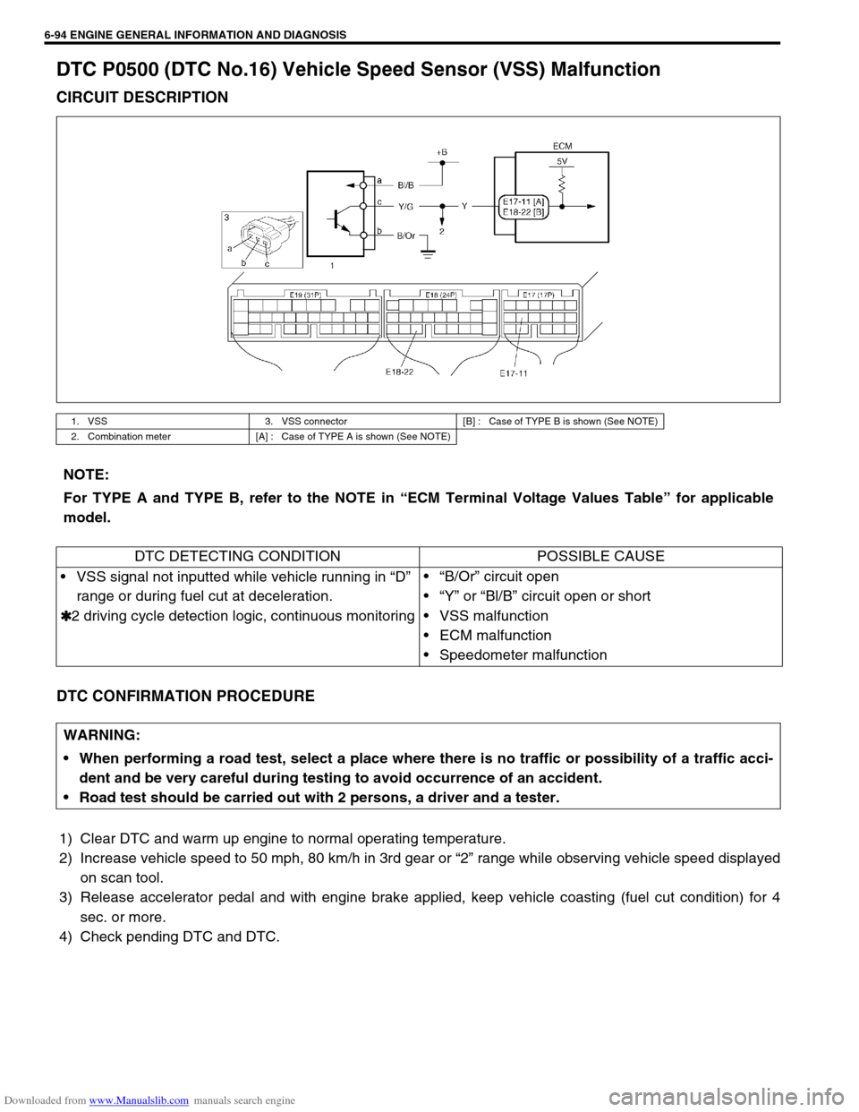
DTC P0500 (DTC No.16) Vehicle Speed Sensor (VSS) Malfunction
CIRCUIT DESCRIPTION
DTC CONFIRMATION PROCEDURE
1) Clear DTC and warm up engine to normal operating temperature.
2) Increase vehicle speed to 50 mph, 80 km/h in 3rd gear or “2” range while observing vehicle speed displayed
on scan tool.
3) Release accelerator pedal and with engine brake applied, keep vehicle coasting (fuel cut condition) for 4
sec. or more.
4) Check pending DTC and DTC.
1. VSS 3. VSS connector [B] : Case of TYPE B is shown (See NOTE)
2. Combination meter [A] : Case of TYPE A is shown (See NOTE)
NOTE:
For TYPE A and TYPE B, refer to the NOTE in “ECM Terminal Voltage Values Table” for applicable
model.
DTC DETECTING CONDITION POSSIBLE CAUSE
VSS signal not inputted while vehicle running in “D”
range or during fuel cut at deceleration.
✱
✱✱ ✱2 driving cycle detection logic, continuous monitoring“B/Or” circuit open
“Y” or “Bl/B” circuit open or short
VSS malfunction
ECM malfunction
Speedometer malfunction
WARNING:
When performing a road test, select a place where there is no traffic or possibility of a traffic acci-
dent and be very careful during testing to avoid occurrence of an accident.
Road test should be carried out with 2 persons, a driver and a tester.
Page 485 of 687
Downloaded from www.Manualslib.com manuals search engine 6A1-4 ENGINE MECHANICAL (M13 ENGINE)
Diagnosis
Diagnosis Table
Refer to “Engine Diagnosis Table” in Section 6.
Compression Check
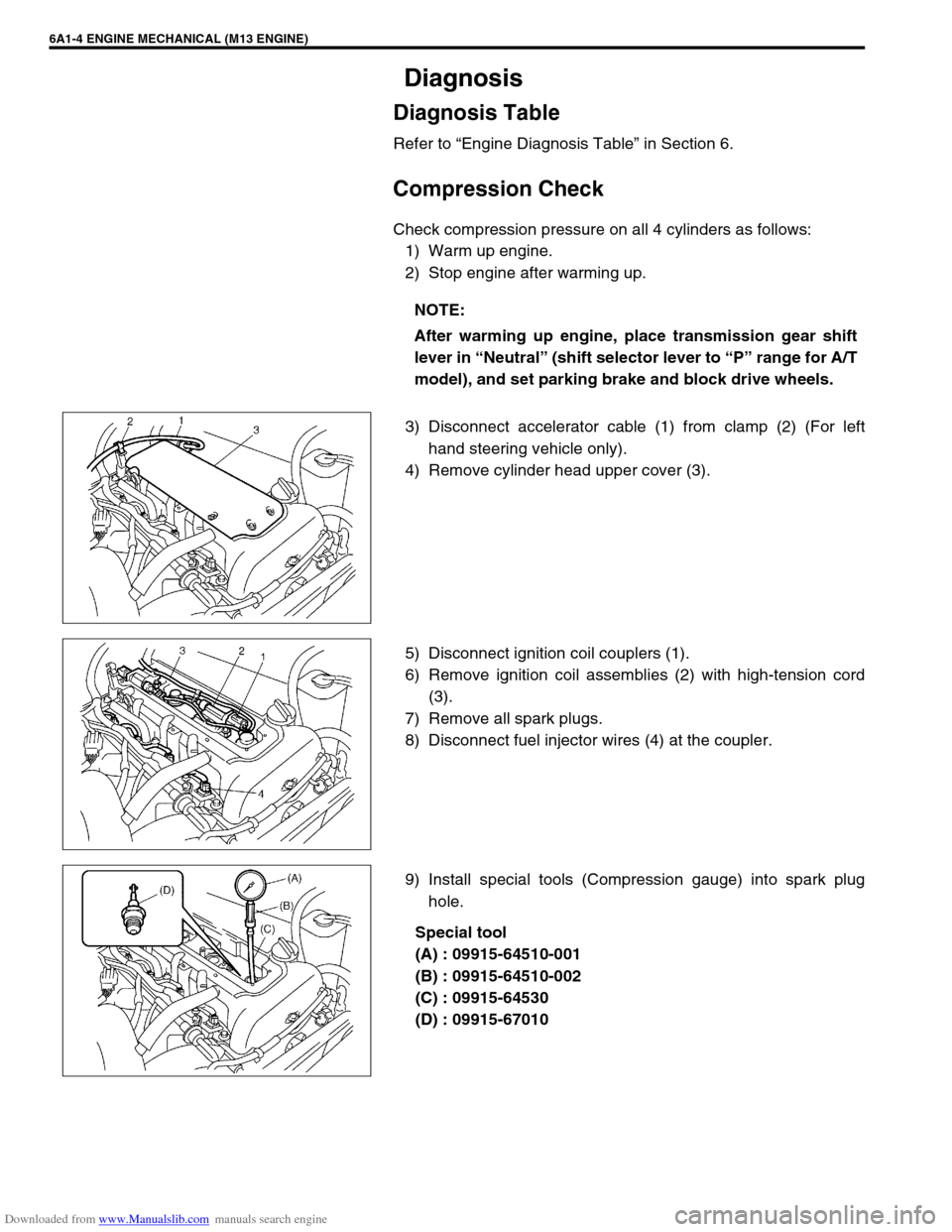
Check compression pressure on all 4 cylinders as follows:
1) Warm up engine.
2) Stop engine after warming up.
3) Disconnect accelerator cable (1) from clamp (2) (For left
hand steering vehicle only).
4) Remove cylinder head upper cover (3).
5) Disconnect ignition coil couplers (1).
6) Remove ignition coil assemblies (2) with high-tension cord
(3).
7) Remove all spark plugs.
8) Disconnect fuel injector wires (4) at the coupler.
9) Install special tools (Compression gauge) into spark plug
hole.
Special tool
(A) : 09915-64510-001
(B) : 09915-64510-002
(C) : 09915-64530
(D) : 09915-67010 NOTE:
After warming up engine, place transmission gear shift
lever in “Neutral” (shift selector lever to “P” range for A/T
model), and set parking brake and block drive wheels.
Page 487 of 687
Downloaded from www.Manualslib.com manuals search engine 6A1-6 ENGINE MECHANICAL (M13 ENGINE)
Engine Vacuum Check
The engine vacuum that develops in the intake line is a good indi-
cator of the condition of the engine. The vacuum checking proce-
dure is as follows:
1) Warm up engine to normal operating temperature.
2) Stop engine and turn off the all electric switches.
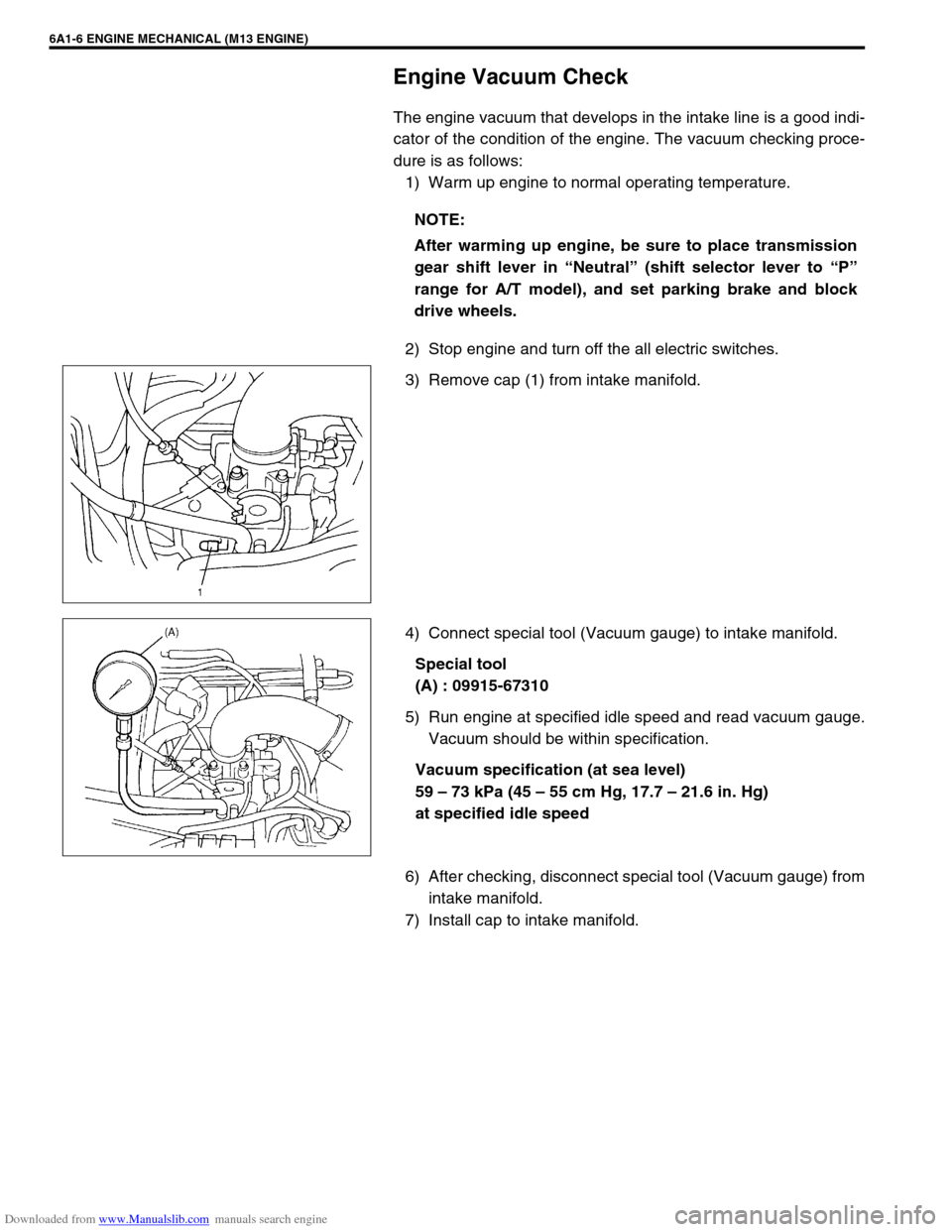
3) Remove cap (1) from intake manifold.
4) Connect special tool (Vacuum gauge) to intake manifold.
Special tool
(A) : 09915-67310
5) Run engine at specified idle speed and read vacuum gauge.
Vacuum should be within specification.
Vacuum specification (at sea level)
59 – 73 kPa (45 – 55 cm Hg, 17.7 – 21.6 in. Hg)
at specified idle speed
6) After checking, disconnect special tool (Vacuum gauge) from
intake manifold.
7) Install cap to intake manifold.NOTE:
After warming up engine, be sure to place transmission
gear shift lever in “Neutral” (shift selector lever to “P”
range for A/T model), and set parking brake and block
drive wheels.
Page 488 of 687
Downloaded from www.Manualslib.com manuals search engine ENGINE MECHANICAL (M13 ENGINE) 6A1-7
Oil Pressure Check
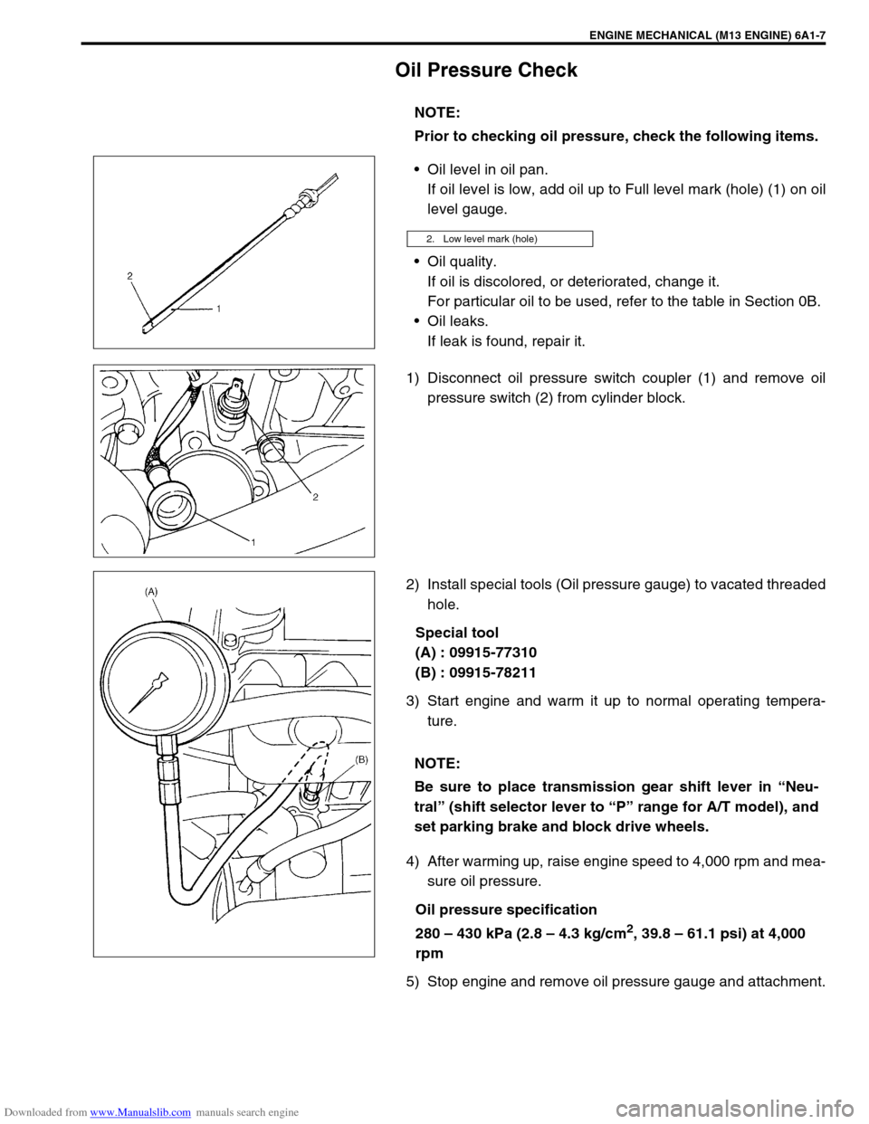
Oil level in oil pan.
If oil level is low, add oil up to Full level mark (hole) (1) on oil
level gauge.
Oil quality.
If oil is discolored, or deteriorated, change it.
For particular oil to be used, refer to the table in Section 0B.
Oil leaks.
If leak is found, repair it.
1) Disconnect oil pressure switch coupler (1) and remove oil
pressure switch (2) from cylinder block.
2) Install special tools (Oil pressure gauge) to vacated threaded
hole.
Special tool
(A) : 09915-77310
(B) : 09915-78211
3) Start engine and warm it up to normal operating tempera-
ture.
4) After warming up, raise engine speed to 4,000 rpm and mea-
sure oil pressure.
Oil pressure specification
280 – 430 kPa (2.8 – 4.3 kg/cm
2, 39.8 – 61.1 psi) at 4,000
rpm
5) Stop engine and remove oil pressure gauge and attachment.NOTE:
Prior to checking oil pressure, check the following items.
2. Low level mark (hole)
NOTE:
Be sure to place transmission gear shift lever in “Neu-
tral” (shift selector lever to “P” range for A/T model), and
set parking brake and block drive wheels.
Page 569 of 687
Downloaded from www.Manualslib.com manuals search engine 6A1-88 ENGINE MECHANICAL (M13 ENGINE)
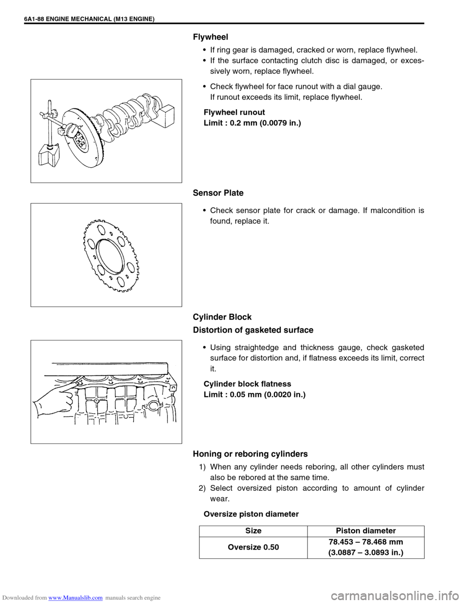
Flywheel
If ring gear is damaged, cracked or worn, replace flywheel.
If the surface contacting clutch disc is damaged, or exces-
sively worn, replace flywheel.
Check flywheel for face runout with a dial gauge.
If runout exceeds its limit, replace flywheel.
Flywheel runout
Limit : 0.2 mm (0.0079 in.)
Sensor Plate
Check sensor plate for crack or damage. If malcondition is
found, replace it.
Cylinder Block
Distortion of gasketed surface
Using straightedge and thickness gauge, check gasketed
surface for distortion and, if flatness exceeds its limit, correct
it.
Cylinder block flatness
Limit : 0.05 mm (0.0020 in.)
Honing or reboring cylinders
1) When any cylinder needs reboring, all other cylinders must
also be rebored at the same time.
2) Select oversized piston according to amount of cylinder
wear.
Oversize piston diameter
Size Piston diameter
Oversize 0.5078.453 – 78.468 mm
(3.0887 – 3.0893 in.)
Page 620 of 687
Downloaded from www.Manualslib.com manuals search engine ENGINE AND EMISSION CONTROL SYSTEM 6E-15
On-Vehicle Service
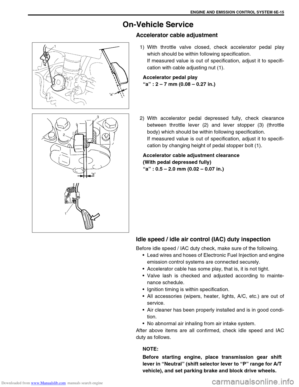
Accelerator cable adjustment
1) With throttle valve closed, check accelerator pedal play
which should be within following specification.
If measured value is out of specification, adjust it to specifi-
cation with cable adjusting nut (1).
Accelerator pedal play
“a” : 2 – 7 mm (0.08 – 0.27 in.)
2) With accelerator pedal depressed fully, check clearance
between throttle lever (2) and lever stopper (3) (throttle
body) which should be within following specification.
If measured value is out of specification, adjust it to specifi-
cation by changing height of pedal stopper bolt (1).
Accelerator cable adjustment clearance
(With pedal depressed fully)
“a” : 0.5 – 2.0 mm (0.02 – 0.07 in.)
Idle speed / idle air control (IAC) duty inspection
Before idle speed / IAC duty check, make sure of the following.
Lead wires and hoses of Electronic Fuel Injection and engine
emission control systems are connected securely.
Accelerator cable has some play, that is, it is not tight.
Valve lash is checked and adjusted according to mainte-
nance schedule.
Ignition timing is within specification.
All accessories (wipers, heater, lights, A/C, etc.) are out of
service.
Air cleaner has been properly installed and is in good condi-
tion.
No abnormal air inhaling from air intake system.
After above items are all confirmed, check idle speed and IAC
duty as follows.
NOTE:
Before starting engine, place transmission gear shift
lever in “Neutral” (shift selector lever to “P” range for A/T
vehicle), and set parking brake and block drive wheels.
Page 642 of 687
Downloaded from www.Manualslib.com manuals search engine ENGINE AND EMISSION CONTROL SYSTEM 6E-37
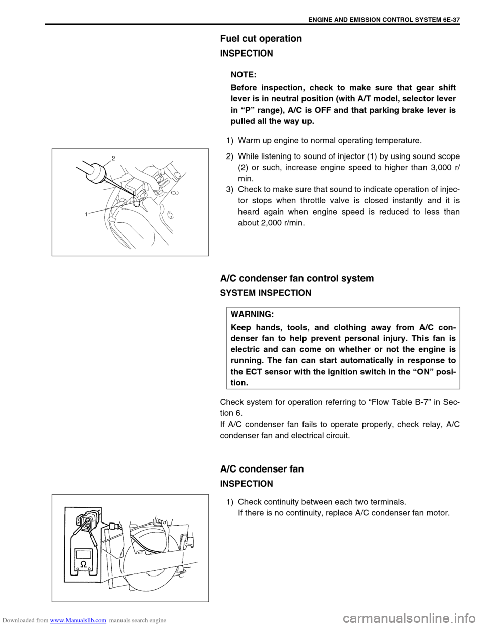
Fuel cut operation
INSPECTION
1) Warm up engine to normal operating temperature.
2) While listening to sound of injector (1) by using sound scope
(2) or such, increase engine speed to higher than 3,000 r/
min.
3) Check to make sure that sound to indicate operation of injec-
tor stops when throttle valve is closed instantly and it is
heard again when engine speed is reduced to less than
about 2,000 r/min.
A/C condenser fan control system
SYSTEM INSPECTION
Check system for operation referring to “Flow Table B-7” in Sec-
tion 6.
If A/C condenser fan fails to operate properly, check relay, A/C
condenser fan and electrical circuit.
A/C condenser fan
INSPECTION
1) Check continuity between each two terminals.
If there is no continuity, replace A/C condenser fan motor. NOTE:
Before inspection, check to make sure that gear shift
lever is in neutral position (with A/T model, selector lever
in “P” range), A/C is OFF and that parking brake lever is
pulled all the way up.
WARNING:
Keep hands, tools, and clothing away from A/C con-
denser fan to help prevent personal injury. This fan is
electric and can come on whether or not the engine is
running. The fan can start automatically in response to
the ECT sensor with the ignition switch in the “ON” posi-
tion.