oxygen sensor SUZUKI JIMNY 2005 3.G Service Owner's Guide
[x] Cancel search | Manufacturer: SUZUKI, Model Year: 2005, Model line: JIMNY, Model: SUZUKI JIMNY 2005 3.GPages: 687, PDF Size: 13.38 MB
Page 619 of 687

Downloaded from www.Manualslib.com manuals search engine 6E-14 ENGINE AND EMISSION CONTROL SYSTEM
For TYPE B (See NOTE)
CONNEC-
TORTERMINAL WIRE COLOR CIRCUITCONNEC-
TORTERMINAL WIRE COLOR CIRCUIT
E191 B Ground for ECM
E187 W Backup power source
2 B/R Ground for drive circuit
8R/GImmobilizer indicator lamp
(if equipped)
3 B/R Ground for drive circuitDuty output terminal (vehicle without
immobilizer indicator lamp)
4 Bl/G Canister purge valve 9––
5 Bl/OrPower steering pressure switch
(if equipped)10 Bl Main relay
6 G/Y IAC valve 11 B/W Ignition switch
7 P/B Heater of HO2S-1 (if equipped) 12 R/W Rear defogger switch
8 W/B No.4 fuel injector 13––
9 R/W No.1 fuel injector 14 W/BIDiagnosis switch terminal
(vehicle without immobilizer indicator
lamp)
10 B/Bl Ground for sensor circuit 15 PTest switch terminal
(vehicle without immobilizer indicator
lamp)
11 W CMP sensor 16 G/W A/C SW signal (if equipped)
12––17 R/Y Lighting switch
13R
R/BlHeated oxygen sensor-1
(if equipped)
CO adjusting resistor (w/o HO2S)18 P/B A/C condenser fan relay (if equipped)
14 G/B ECT sensor 19 W/G Fuel pump relay
15 Lg/B IAT sensor 20B/Y (M/T)
B/R (A/T)Engine start signal
16 Lg TP sensor 21 G/W Stop lamp switch
17 Gr/BIEGR valve (stepper motor coil 3, if
equipped)22 Y Vehicle speed sensor
18 GrEGR valve (stepper motor coil 1, if
equipped)23––
19 Br/BIG coil assembly for No.2 and 3 spark
plugs24––
20 Br/WIG coil assembly for No.1 and 4 spark
plugs
21 R/G No.2 fuel injector
E171 W/R A/C evaporator temp. sensor
22 Lg/R Power supply for sensor 2 R R-range signal (A/T)
23 G/R CKP sensor 3––
24––4––
25 W Knock sensor 5 B/Or Overdrive cut signal (A/T)
26 G MAP sensor 6 G/Y D-range idle-up signal (A/T)
27––7 Y/B Data link connector
28 Gr/BEGR valve (stepper motor coil 4, if
equipped)8––
29 Gr/REGR valve (stepper motor coil 2, if
equipped)9 V/Y Malfunction indicator lamp
30––10––
31 W/G No.3 fuel injector 11 P/G Data link connector (12 V)
12 G ABS signal (if equipped)
E181 P A/C compressor clutch (if equipped) 13 Bl/Y Heater blower switch
2––14 B/Bl Ground for sensor
3––15 B/R Throttle opening sensor
4 R/BI Heater of HO2S-2 (if equipped) 16 Br Tachometer
5 Bl/B Power source 17––
6 Bl/B Power source
NOTE:
See NOTE in “ECM INPUT / OUTPUT CIRCUIT DIAGRAM” for applicable model.
Page 622 of 687
Downloaded from www.Manualslib.com manuals search engine ENGINE AND EMISSION CONTROL SYSTEM 6E-17
Idle mixture inspection / adjustment (vehicle without
heated oxygen sensor)
All vehicles not equipped with heated oxygen sensor are shipped
with their CO % factory adjusted as follows.
Engine idle mixture (CO %)
0.5 – 1.5 % at specified idle speed
Idle mixture adjustment should never be changed from the origi-
nal factory setting. However, if during diagnosis, the check indi-
cates idle mixture to be the cause of a driver performance
complaint or emission failure, the idle mixture can be adjusted
using the following procedures.
1) Check idle speed according to “Idle Speed / Idle Air Control
(IAC) Duty Inspection” in this section.
2) Using exhaust gas tester, check that idle mixture CO % is
within above specification. If it is out of specification, adjust it
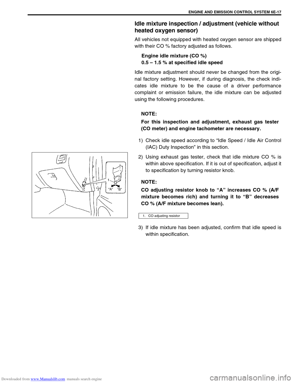
to specification by turning resistor knob.
3) If idle mixture has been adjusted, confirm that idle speed is
within specification. NOTE:
For this inspection and adjustment, exhaust gas tester
(CO meter) and engine tachometer are necessary.
NOTE:
CO adjusting resistor knob to “A” increases CO % (A/F
mixture becomes rich) and turning it to “B” decreases
CO % (A/F mixture becomes lean).
1. CO adjusting resistor
Page 638 of 687
Downloaded from www.Manualslib.com manuals search engine ENGINE AND EMISSION CONTROL SYSTEM 6E-33
Tighten ECT sensor (1) to specified torque.
Tightening torque
ECT sensor (a) : 15 N·m (1.5 kg-m, 11.5 lb-ft)
Connect connector to ECT sensor (1) securely.
Refill coolant referring to “Cooling System Flush and Refill”
in Section 6B.
Heated oxygen sensor (Sensor-1 and sensor-2)
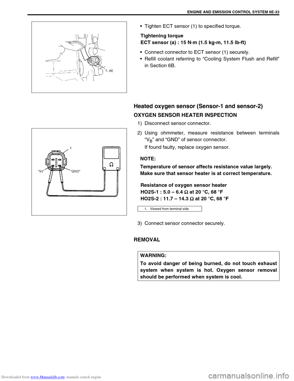
OXYGEN SENSOR HEATER INSPECTION
1) Disconnect sensor connector.
2) Using ohmmeter, measure resistance between terminals
“V
B” and “GND” of sensor connector.
If found faulty, replace oxygen sensor.
Resistance of oxygen sensor heater
HO2S-1 : 5.0 – 6.4
Ω
ΩΩ Ω at 20 °C, 68 °F
HO2S-2 : 11.7 – 14.3
Ω
ΩΩ Ω at 20 °C, 68 °F
3) Connect sensor connector securely.
REMOVAL
NOTE:
Temperature of sensor affects resistance value largely.
Make sure that sensor heater is at correct temperature.
1. Viewed from terminal side
WARNING:
To avoid danger of being burned, do not touch exhaust
system when system is hot. Oxygen sensor removal
should be performed when system is cool.
Page 639 of 687
Downloaded from www.Manualslib.com manuals search engine 6E-34 ENGINE AND EMISSION CONTROL SYSTEM
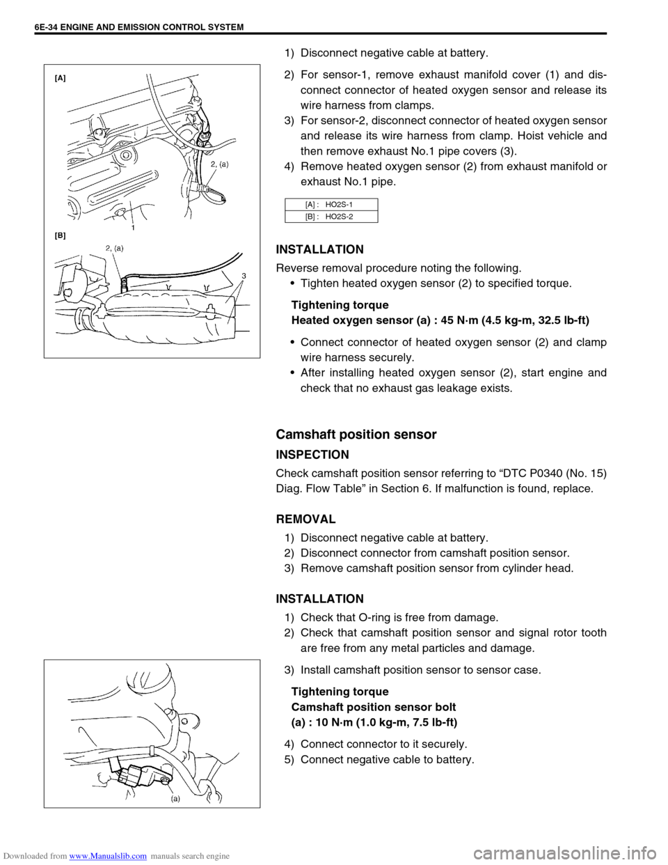
1) Disconnect negative cable at battery.
2) For sensor-1, remove exhaust manifold cover (1) and dis-
connect connector of heated oxygen sensor and release its
wire harness from clamps.
3) For sensor-2, disconnect connector of heated oxygen sensor
and release its wire harness from clamp. Hoist vehicle and
then remove exhaust No.1 pipe covers (3).
4) Remove heated oxygen sensor (2) from exhaust manifold or
exhaust No.1 pipe.
INSTALLATION
Reverse removal procedure noting the following.
Tighten heated oxygen sensor (2) to specified torque.
Tightening torque
Heated oxygen sensor (a) : 45 N·m (4.5 kg-m, 32.5 lb-ft)
Connect connector of heated oxygen sensor (2) and clamp
wire harness securely.
After installing heated oxygen sensor (2), start engine and
check that no exhaust gas leakage exists.
Camshaft position sensor
INSPECTION
Check camshaft position sensor referring to “DTC P0340 (No. 15)
Diag. Flow Table” in Section 6. If malfunction is found, replace.
REMOVAL
1) Disconnect negative cable at battery.
2) Disconnect connector from camshaft position sensor.
3) Remove camshaft position sensor from cylinder head.
INSTALLATION
1) Check that O-ring is free from damage.
2) Check that camshaft position sensor and signal rotor tooth
are free from any metal particles and damage.
3) Install camshaft position sensor to sensor case.
Tightening torque
Camshaft position sensor bolt
(a) : 10 N·m (1.0 kg-m, 7.5 lb-ft)
4) Connect connector to it securely.
5) Connect negative cable to battery.
[A] : HO2S-1
[B] : HO2S-2
Page 648 of 687
Downloaded from www.Manualslib.com manuals search engine ENGINE AND EMISSION CONTROL SYSTEM 6E-43
Tightening Torque Specifications
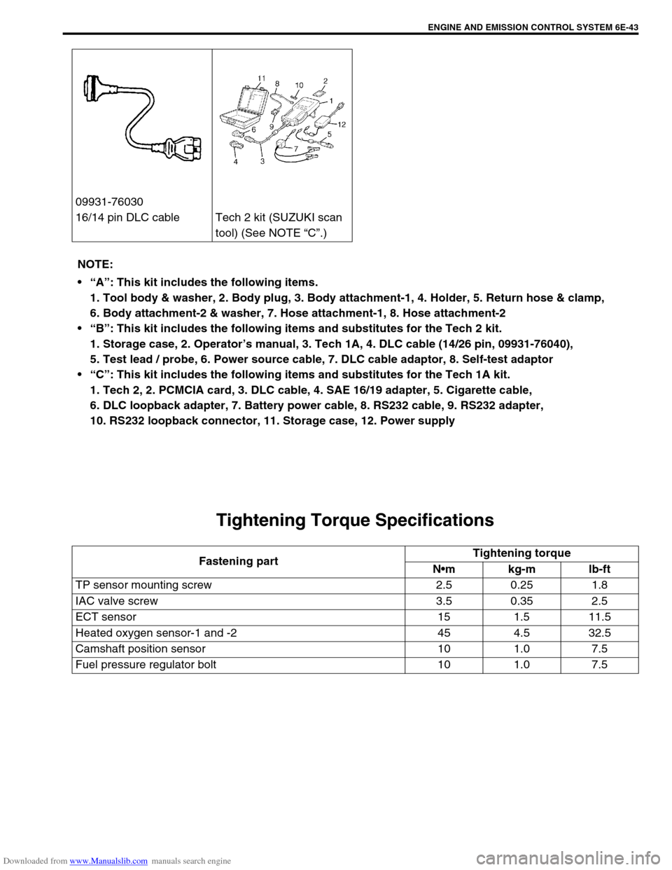
09931-76030
16/14 pin DLC cable Tech 2 kit (SUZUKI scan
tool) (See NOTE “C”.)
NOTE:
“A”: This kit includes the following items.
1. Tool body & washer, 2. Body plug, 3. Body attachment-1, 4. Holder, 5. Return hose & clamp,
6. Body attachment-2 & washer, 7. Hose attachment-1, 8. Hose attachment-2
“B”: This kit includes the following items and substitutes for the Tech 2 kit.
1. Storage case, 2. Operator’s manual, 3. Tech 1A, 4. DLC cable (14/26 pin, 09931-76040),
5. Test lead / probe, 6. Power source cable, 7. DLC cable adaptor, 8. Self-test adaptor
“C”: This kit includes the following items and substitutes for the Tech 1A kit.
1. Tech 2, 2. PCMCIA card, 3. DLC cable, 4. SAE 16/19 adapter, 5. Cigarette cable,
6. DLC loopback adapter, 7. Battery power cable, 8. RS232 cable, 9. RS232 adapter,
10. RS232 loopback connector, 11. Storage case, 12. Power supply
Fastening partTightening torque
Nm kg-m lb-ft
TP sensor mounting screw 2.5 0.25 1.8
IAC valve screw 3.5 0.35 2.5
ECT sensor 15 1.5 11.5
Heated oxygen sensor-1 and -2 45 4.5 32.5
Camshaft position sensor 10 1.0 7.5
Fuel pressure regulator bolt 10 1.0 7.5
Page 687 of 687
Downloaded from www.Manualslib.com manuals search engine 6K-2 EXHAUST SYSTEM
On-Vehicle Service
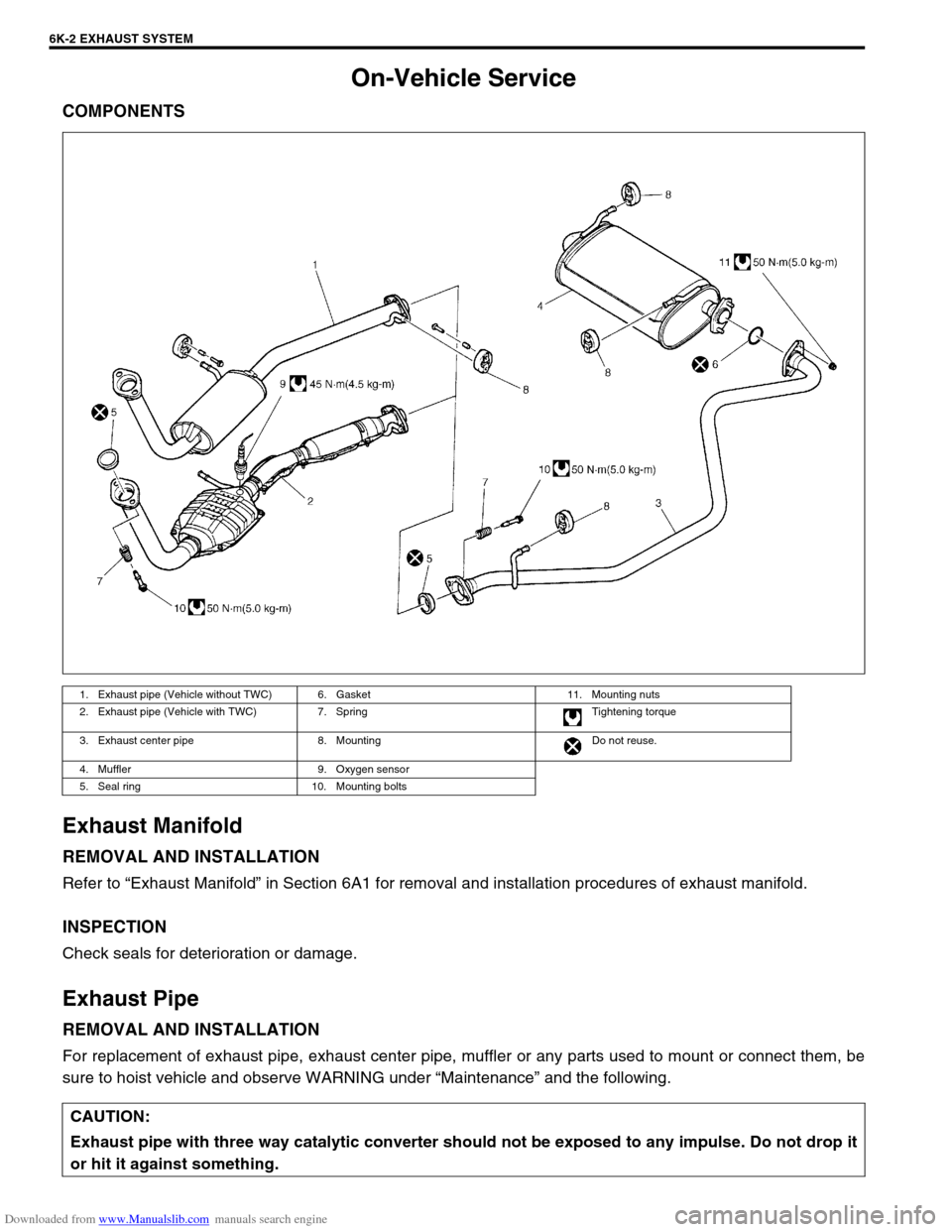
COMPONENTS
Exhaust Manifold
REMOVAL AND INSTALLATION
Refer to “Exhaust Manifold” in Section 6A1 for removal and installation procedures of exhaust manifold.
INSPECTION
Check seals for deterioration or damage.
Exhaust Pipe
REMOVAL AND INSTALLATION
For replacement of exhaust pipe, exhaust center pipe, muffler or any parts used to mount or connect them, be
sure to hoist vehicle and observe WARNING under “Maintenance” and the following.
1. Exhaust pipe (Vehicle without TWC) 6. Gasket 11. Mounting nuts
2. Exhaust pipe (Vehicle with TWC) 7. Spring Tightening torque
3. Exhaust center pipe 8. Mounting Do not reuse.
4. Muffler 9. Oxygen sensor
5. Seal ring 10. Mounting bolts
CAUTION:
Exhaust pipe with three way catalytic converter should not be exposed to any impulse. Do not drop it
or hit it against something.