battery SUZUKI JIMNY 2005 3.G Service Repair Manual
[x] Cancel search | Manufacturer: SUZUKI, Model Year: 2005, Model line: JIMNY, Model: SUZUKI JIMNY 2005 3.GPages: 687, PDF Size: 13.38 MB
Page 390 of 687

Downloaded from www.Manualslib.com manuals search engine ENGINE GENERAL INFORMATION AND DIAGNOSIS 6-33
Inspection of ECM and Its Circuits
ECM and its circuits can be checked at ECM wiring connectors by
measuring voltage and resistance.
VOLTAGE CHECK
1) Remove ECM from body referring to Section 6E.
2) Check voltage at each terminal of connectors connected.CAUTION:
ECM cannot be checked by itself. It is strictly prohibited
to connect voltmeter or ohmmeter to ECM with connector
disconnected from it.
NOTE:
As each terminal voltage is affected by the battery volt-
age, confirm that it is 11 V or more when ignition switch
is ON.
1. ECM
2. ECM connectors (Viewed from harness side)
Page 406 of 687
![SUZUKI JIMNY 2005 3.G Service Repair Manual Downloaded from www.Manualslib.com manuals search engine ENGINE GENERAL INFORMATION AND DIAGNOSIS 6-49
[A] Fig. 1 for Step 2 / [B] Fig. 2 for Step 33 Check Wire Harness.
1) Disconnect MAP sensor conne SUZUKI JIMNY 2005 3.G Service Repair Manual Downloaded from www.Manualslib.com manuals search engine ENGINE GENERAL INFORMATION AND DIAGNOSIS 6-49
[A] Fig. 1 for Step 2 / [B] Fig. 2 for Step 33 Check Wire Harness.
1) Disconnect MAP sensor conne](/img/20/7588/w960_7588-405.png)
Downloaded from www.Manualslib.com manuals search engine ENGINE GENERAL INFORMATION AND DIAGNOSIS 6-49
[A] Fig. 1 for Step 2 / [B] Fig. 2 for Step 33 Check Wire Harness.
1) Disconnect MAP sensor connector with
ignition switch OFF.
2) Check for proper connection of MAP sensor
at “G” and “B/Bl” wire terminals.
3) If OK, then with ignition switch ON, check
voltage at each of “Lg/R” and “G” wire termi-
nals and body ground. See Fig. 2.
Is voltage about 4 – 6 V at each terminal?Go to Step 4.“Lg/R” wire open or
shorted to ground circuit
or shorted to power circuit
(See NOTE), “G” wire
open or shorted to
ground, poor E19-26 con-
nection or E19-22 con-
nection.
If wire and connection are
OK, confirm that MAP
sensor is normal and then
substitute a known-good
ECM and recheck.
4 Check MAP sensor according to “MAP Sensor
Individual Check” below.
Is it in good condition?“Lg/R” wire shorted to “G”
wire, “B/Bl” wire open,
poor E19-10 connection.
If wire and connection are
OK, substitute a known-
good ECM and recheck.Replace MAP sensor. Step Action Yes No
NOTE:
When battery voltage is applied to “Lg/R” wire, it is possible that MAP sensor is also faulty.
Page 460 of 687
Downloaded from www.Manualslib.com manuals search engine ENGINE GENERAL INFORMATION AND DIAGNOSIS 6-103
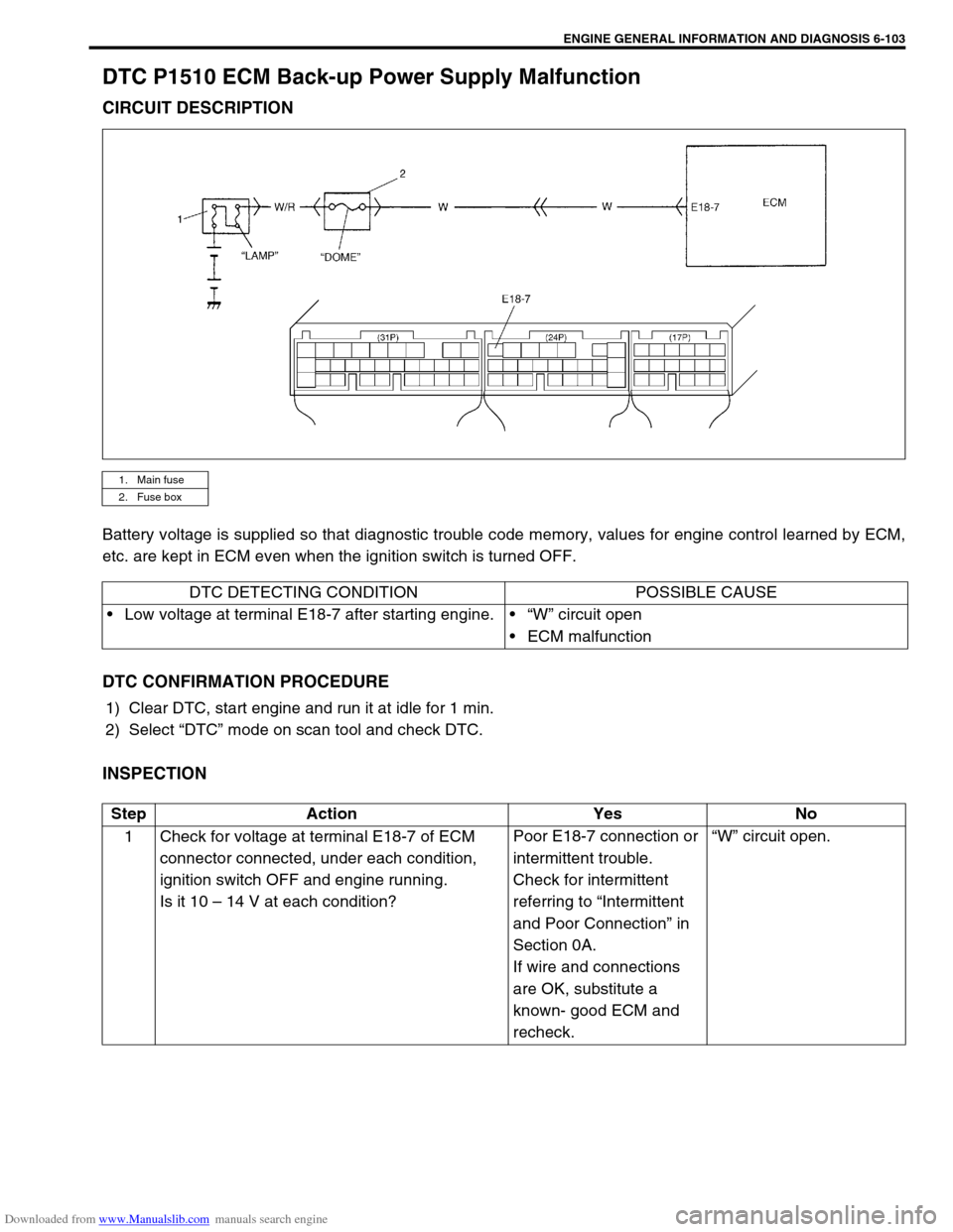
DTC P1510 ECM Back-up Power Supply Malfunction
CIRCUIT DESCRIPTION
Battery voltage is supplied so that diagnostic trouble code memory, values for engine control learned by ECM,
etc. are kept in ECM even when the ignition switch is turned OFF.
DTC CONFIRMATION PROCEDURE
1) Clear DTC, start engine and run it at idle for 1 min.
2) Select “DTC” mode on scan tool and check DTC.
INSPECTION
1. Main fuse
2. Fuse box
DTC DETECTING CONDITION POSSIBLE CAUSE
Low voltage at terminal E18-7 after starting engine.“W” circuit open
ECM malfunction
Step Action Yes No
1 Check for voltage at terminal E18-7 of ECM
connector connected, under each condition,
ignition switch OFF and engine running.
Is it 10 – 14 V at each condition?Poor E18-7 connection or
intermittent trouble.
Check for intermittent
referring to “Intermittent
and Poor Connection” in
Section 0A.
If wire and connections
are OK, substitute a
known- good ECM and
recheck.“W” circuit open.
Page 468 of 687
![SUZUKI JIMNY 2005 3.G Service Repair Manual Downloaded from www.Manualslib.com manuals search engine ENGINE GENERAL INFORMATION AND DIAGNOSIS 6-111
[A] Fig. 1 for Step 2 / [B] Fig. 2 for Step 3 / [C] Fig. 3 for Step 44 Check Fuel Pump Relay for SUZUKI JIMNY 2005 3.G Service Repair Manual Downloaded from www.Manualslib.com manuals search engine ENGINE GENERAL INFORMATION AND DIAGNOSIS 6-111
[A] Fig. 1 for Step 2 / [B] Fig. 2 for Step 3 / [C] Fig. 3 for Step 44 Check Fuel Pump Relay for](/img/20/7588/w960_7588-467.png)
Downloaded from www.Manualslib.com manuals search engine ENGINE GENERAL INFORMATION AND DIAGNOSIS 6-111
[A] Fig. 1 for Step 2 / [B] Fig. 2 for Step 3 / [C] Fig. 3 for Step 44 Check Fuel Pump Relay for Operation.
1) Check resistance between each two termi-
nals of fuel pump relay. See Fig.3.
Fuel pump relay resistance
Between terminals “A” and “B” : Infinity
Between terminals “C” and “D”: 100 – 150
Ω
ΩΩ Ω
2) Check that there is continuity between ter-
minals “A” and “B” when battery is con-
nected to terminals “C” and “D”. See Fig. 3.
Is fuel pump relay in good condition?“W/G” circuit open or poor
E18-19 connection.
If wire and connection are
OK, substitute a known-
good ECM and recheck.Replace fuel pump
relay. Step Action Yes No
CAUTION:
Check to make sure that connection is made between correct terminals. Wrong connection can cause
damage to ECM, wire harness, etc.
Page 478 of 687

Downloaded from www.Manualslib.com manuals search engine ENGINE GENERAL INFORMATION AND DIAGNOSIS 6-121
TAble B-7 A/C Condenser Fan Control System Check
INSPECTION
Step Action Yes No
1 Check Fan Control System.
1) Connect scan tool to DLC with ignition switch OFF. See
Fig. 1.
2) Start engine and select “DATA LIST” mode on scan tool.
3) Warm up engine until coolant temp. is 110 °C, 230 °F or
higher and A/C switch turn OFF. (If engine coolant temp.
does not rise, check engine cooling system or ECT sen-
sor.)
Is A/C condenser fan started when engine coolant temp.
reached above temp.?A/C condenser fan con-
trol system is in good
condition.Go to Step 2.
2 Check A/C Condenser Fan Relay and Its Circuit.
1) Check DTC and pending DTC with scan tool.
Is DTC P0481 displayed?Go to DTC P0481 Diag.
Flow Table.Go to Step 3.
3 Check A/C Condenser Fan Relay (1).
1) Turn ignition switch OFF and remove A/C condenser fan
relay.
2) Check for proper connection to relay at terminals “A”
and “B”.
3) If OK, check that there is continuity between “A” and “B”
when battery is connected to terminals “C” and “D”. See
Fig. 2.
Is check result satisfactory?Go to Step 4. Replace A/C
condenser fan
relay.
Page 479 of 687
![SUZUKI JIMNY 2005 3.G Service Repair Manual Downloaded from www.Manualslib.com manuals search engine 6-122 ENGINE GENERAL INFORMATION AND DIAGNOSIS
[A] Fig. 1 for Step 1 / [B] Fig. 2 for Step 3
Fig. 3 for Step 44 Check A/C Condenser Fan (1).
1) SUZUKI JIMNY 2005 3.G Service Repair Manual Downloaded from www.Manualslib.com manuals search engine 6-122 ENGINE GENERAL INFORMATION AND DIAGNOSIS
[A] Fig. 1 for Step 1 / [B] Fig. 2 for Step 3
Fig. 3 for Step 44 Check A/C Condenser Fan (1).
1)](/img/20/7588/w960_7588-478.png)
Downloaded from www.Manualslib.com manuals search engine 6-122 ENGINE GENERAL INFORMATION AND DIAGNOSIS
[A] Fig. 1 for Step 1 / [B] Fig. 2 for Step 3
Fig. 3 for Step 44 Check A/C Condenser Fan (1).
1) Turn ignition switch OFF.
2) Disconnect fan motor connector (2).
3) Check for proper connection to motor at “R/Bl” and “B”
terminals.
4) If OK, connect battery to motor and check for operation.
See Fig. 3.
Is it in good condition?“R”, “R/Bl” or “B” circuit
open.Replace A/C
condenser fan
motor. Step Action Yes No
Page 480 of 687
Downloaded from www.Manualslib.com manuals search engine ENGINE GENERAL INFORMATION AND DIAGNOSIS 6-123
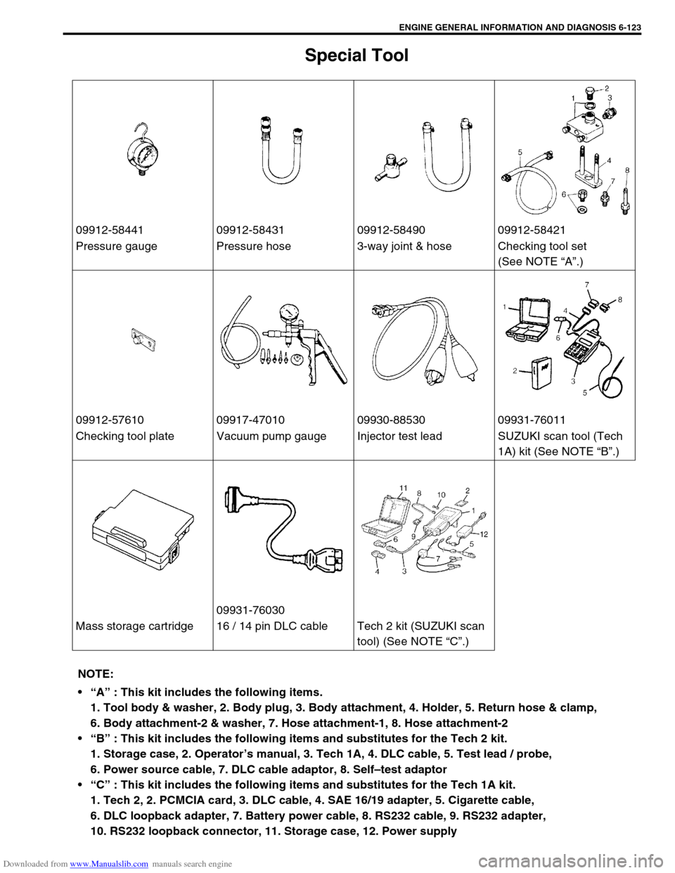
Special Tool
09912-58441 09912-58431 09912-58490 09912-58421
Pressure gauge Pressure hose 3-way joint & hose Checking tool set
(See NOTE “A”.)
09912-57610 09917-47010 09930-88530 09931-76011
Checking tool plate Vacuum pump gauge Injector test lead SUZUKI scan tool (Tech
1A) kit (See NOTE “B”.)
09931-76030
Mass storage cartridge 16 / 14 pin DLC cable Tech 2 kit (SUZUKI scan
tool) (See NOTE “C”.)
NOTE:
“A” : This kit includes the following items.
1. Tool body & washer, 2. Body plug, 3. Body attachment, 4. Holder, 5. Return hose & clamp,
6. Body attachment-2 & washer, 7. Hose attachment-1, 8. Hose attachment-2
“B” : This kit includes the following items and substitutes for the Tech 2 kit.
1. Storage case, 2. Operator’s manual, 3. Tech 1A, 4. DLC cable, 5. Test lead / probe,
6. Power source cable, 7. DLC cable adaptor, 8. Self–test adaptor
“C” : This kit includes the following items and substitutes for the Tech 1A kit.
1. Tech 2, 2. PCMCIA card, 3. DLC cable, 4. SAE 16/19 adapter, 5. Cigarette cable,
6. DLC loopback adapter, 7. Battery power cable, 8. RS232 cable, 9. RS232 adapter,
10. RS232 loopback connector, 11. Storage case, 12. Power supply
Page 482 of 687
Downloaded from www.Manualslib.com manuals search engine ENGINE MECHANICAL (M13 ENGINE) 6A1-1
6F1
6G
6H
6K
7A
7A1
7B1
7C1
7D
7E
7F
8A
8C
6A1
8E
9
9
10B
SECTION 6A1
ENGINE MECHANICAL (M13 ENGINE)
CONTENTS
General Description ......................................6A1-2
Engine ......................................................... 6A1-2
Engine Lubrication ...................................... 6A1-3
Diagnosis .......................................................6A1-4
Diagnosis Table .......................................... 6A1-4
Compression Check .................................... 6A1-4
Engine Vacuum Check ................................ 6A1-6
Oil Pressure Check ..................................... 6A1-7
Valve Lash (Clearance) ............................... 6A1-9
On-Vehicle Service......................................6A1-13
Air Cleaner Element .................................. 6A1-13
Air Cleaner Assembly ................................ 6A1-14
Knock Sensor ............................................ 6A1-14
Cylinder Head Cover ................................. 6A1-15
Throttle Body and Intake Manifold ............ 6A1-18
Exhaust Manifold ....................................... 6A1-21Oil Pan and Oil Pump Strainer .................. 6A1-24
Timing Chain Cover .................................. 6A1-28
Oil Pump ................................................... 6A1-33
Timing Chain and Chain Tensioner .......... 6A1-37
Camshaft, Tappet and Shim ..................... 6A1-42
Valves and Cylinder Head ........................ 6A1-48
Pistons, Piston Rings, Connecting
Rods and Cylinders................................... 6A1-62
Engine Mountings ..................................... 6A1-72
Unit Repair Overhaul .................................. 6A1-73
Engine Assembly ...................................... 6A1-73
Main Bearings, Crankshaft and Cylinder
Block ......................................................... 6A1-79
Required Service Material .......................... 6A1-93
Tightening Torque Specification ............... 6A1-93
Special Tool ................................................. 6A1-94
WARNING:
For vehicles equipped with Supplemental Restraint (Air Bag) System:
Service on and around the air bag system components or wiring must be performed only by an
authorized SUZUKI dealer. Refer to “Air Bag System Components and Wiring Location View” under
“General Description” in air bag system section in order to confirm whether you are performing ser-
vice on or near the air bag system components or wiring. Please observe all WARNINGS and “Ser-
vice Precautions” under “On-Vehicle Service” in air bag system section before performing service
on or around the air bag system components or wiring. Failure to follow WARNINGS could result in
unintentional activation of the system or could render the system inoperative. Either of these two
conditions may result in severe injury.
Technical service work must be started at least 90 seconds after the ignition switch is turned to the
“LOCK” position and the negative cable is disconnected from the battery. Otherwise, the system
may be activated by reserve energy in the Sensing and Diagnostic Module (SDM).
Page 486 of 687
Downloaded from www.Manualslib.com manuals search engine ENGINE MECHANICAL (M13 ENGINE) 6A1-5
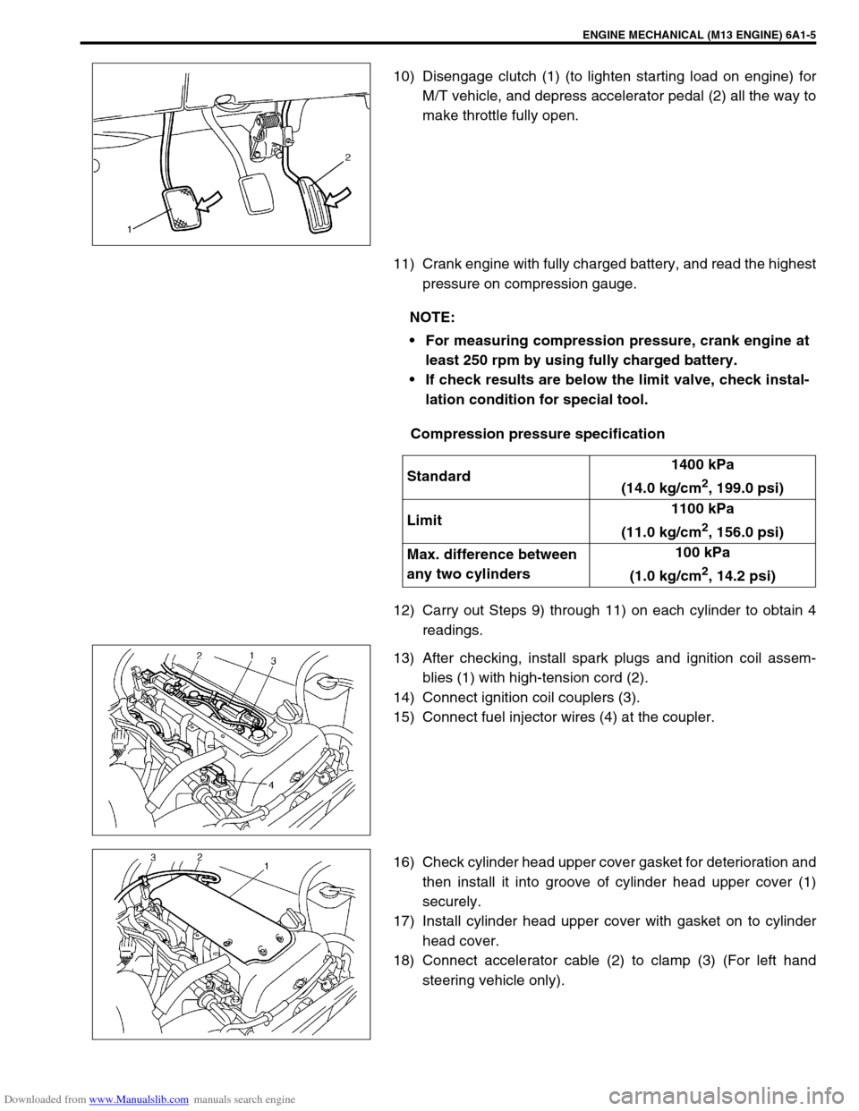
10) Disengage clutch (1) (to lighten starting load on engine) for
M/T vehicle, and depress accelerator pedal (2) all the way to
make throttle fully open.
11) Crank engine with fully charged battery, and read the highest
pressure on compression gauge.
Compression pressure specification
12) Carry out Steps 9) through 11) on each cylinder to obtain 4
readings.
13) After checking, install spark plugs and ignition coil assem-
blies (1) with high-tension cord (2).
14) Connect ignition coil couplers (3).
15) Connect fuel injector wires (4) at the coupler.
16) Check cylinder head upper cover gasket for deterioration and
then install it into groove of cylinder head upper cover (1)
securely.
17) Install cylinder head upper cover with gasket on to cylinder
head cover.
18) Connect accelerator cable (2) to clamp (3) (For left hand
steering vehicle only).
NOTE:
For measuring compression pressure, crank engine at
least 250 rpm by using fully charged battery.
If check results are below the limit valve, check instal-
lation condition for special tool.
Standard1400 kPa
(14.0 kg/cm
2, 199.0 psi)
Limit1100 kPa
(11.0 kg/cm
2, 156.0 psi)
Max. difference between
any two cylinders100 kPa
(1.0 kg/cm
2, 14.2 psi)
Page 490 of 687
Downloaded from www.Manualslib.com manuals search engine ENGINE MECHANICAL (M13 ENGINE) 6A1-9
Valve Lash (Clearance)
1) Remove negative cable at battery.
2) Remove cylinder head cover referring to “Cylinder Head
Cover” in this section.
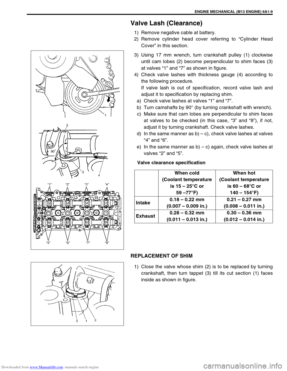
3) Using 17 mm wrench, turn crankshaft pulley (1) clockwise
until cam lobes (2) become perpendicular to shim faces (3)
at valves “1” and “7” as shown in figure.
4) Check valve lashes with thickness gauge (4) according to
the following procedure.
If valve lash is out of specification, record valve lash and
adjust it to specification by replacing shim.
a) Check valve lashes at valves “1” and “7”.
b) Turn camshafts by 90° (by turning crankshaft with wrench).
c) Make sure that cam lobes are perpendicular to shim faces
at valves to be checked (in this case, “3” and “8”), if not,
adjust it by turning crankshaft. Check valve lashes.
d) In the same manner as b) – c), check valve lashes at valves
“4” and “6”.
e) In the same manner as b) – c) again, check valve lashes at
valves “2” and “5”.
Valve clearance specification
REPLACEMENT OF SHIM
1) Close the valve whose shim (2) is to be replaced by turning
crankshaft, then turn tappet (3) till its cut section (1) faces
inside as shown in figure.When cold
(Coolant temperature
is 15 – 25°C or
59 –77°F)When hot
(Coolant temperature
is 60 – 68°C or
140 – 154°F)
Intake0.18 – 0.22 mm
(0.007 – 0.009 in.)0.21 – 0.27 mm
(0.008 – 0.011 in.)
Exhaust0.28 – 0.32 mm
(0.011 – 0.013 in.)0.30 – 0.36 mm
(0.012 – 0.014 in.)