drive SUZUKI JIMNY 2005 3.G Service Repair Manual
[x] Cancel search | Manufacturer: SUZUKI, Model Year: 2005, Model line: JIMNY, Model: SUZUKI JIMNY 2005 3.GPages: 687, PDF Size: 13.38 MB
Page 325 of 687

Downloaded from www.Manualslib.com manuals search engine 5E-8 ANTILOCK BRAKE SYSTEM (ABS)
2) DRIVING TEST
Test drive the vehicle at 40 km/h for more than a minute and check if any trouble symptom (such as abnor-
mal lighting of “ABS” warning lamp) exists.
If the malfunction DTC is confirmed again at ignition switch ON, driving test as described in above is not nec-
essary. Proceed to Step 3.
3) DIAGNOSTIC TROUBLE CODE CHECK
Recheck diagnostic trouble code referring to “DTC Check” in this section.
4) DIAGNOSTIC TROUBLE CODE FLOW TABLE
According to Diagnostic Flow Table for the diagnostic trouble code confirmed in Step 3, locate the cause of
the trouble, namely in a sensor, switch, wire harness, connector, actuator, ABS control module or other part
and repair or replace faulty parts.
5)“DIAGNOSIS TABLE” IN SECTION 5
Check the parts or system suspected as a possible cause referring to “Diagnosis Table” in Section 5 and
based on symptoms appearing on the vehicle (symptoms obtained through Step 1)-a, 1)-b and 2) and repair
or replace faulty parts, if any.
6) CHECK FOR INTERMITTENT PROBLEM
Check parts where an intermittent trouble is easy to occur (e.g., wire harness, connector, etc.), referring to
Intermittent Trouble in Section 0A and related circuit of trouble code recorded in Step 1)-c.
7) FINAL CONFIRMATION TEST
Confirm that the problem symptom has gone and the ABS is free from any abnormal conditions. If what has
been repaired is related to the malfunction DTC, clear the DTC once and perform test driving and confirm
that a normal code is indicated.
Page 326 of 687
Downloaded from www.Manualslib.com manuals search engine ANTILOCK BRAKE SYSTEM (ABS) 5E-9
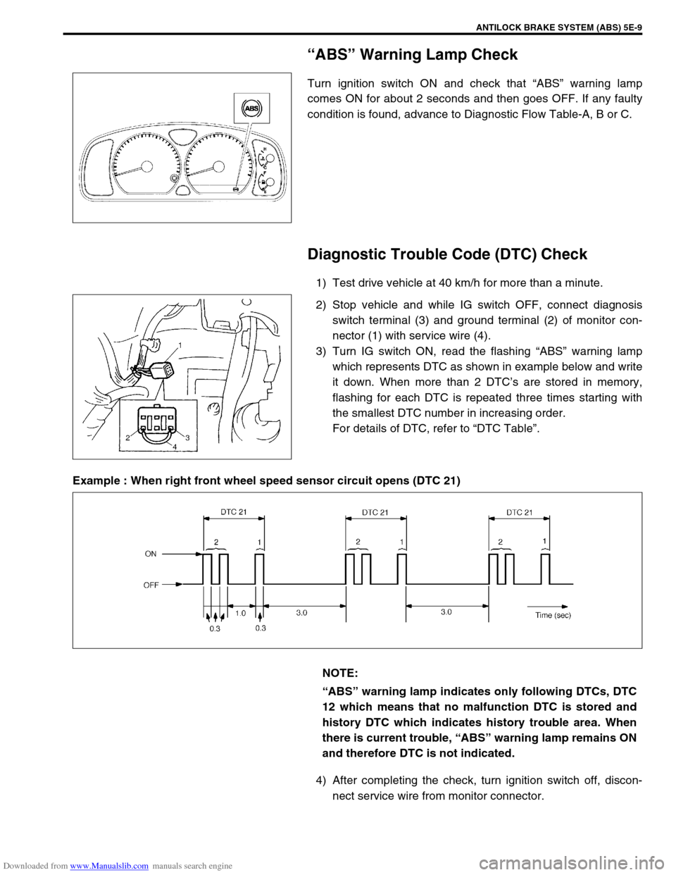
“ABS” Warning Lamp Check
Turn ignition switch ON and check that “ABS” warning lamp
comes ON for about 2 seconds and then goes OFF. If any faulty
condition is found, advance to Diagnostic Flow Table-A, B or C.
Diagnostic Trouble Code (DTC) Check
1) Test drive vehicle at 40 km/h for more than a minute.
2) Stop vehicle and while IG switch OFF, connect diagnosis
switch terminal (3) and ground terminal (2) of monitor con-
nector (1) with service wire (4).
3) Turn IG switch ON, read the flashing “ABS” warning lamp
which represents DTC as shown in example below and write
it down. When more than 2 DTC’s are stored in memory,
flashing for each DTC is repeated three times starting with
the smallest DTC number in increasing order.
For details of DTC, refer to “DTC Table”.
Example : When right front wheel speed sensor circuit opens (DTC 21)
4) After completing the check, turn ignition switch off, discon-
nect service wire from monitor connector.
NOTE:
“ABS” warning lamp indicates only following DTCs, DTC
12 which means that no malfunction DTC is stored and
history DTC which indicates history trouble area. When
there is current trouble, “ABS” warning lamp remains ON
and therefore DTC is not indicated.
Page 329 of 687
Downloaded from www.Manualslib.com manuals search engine 5E-12 ANTILOCK BRAKE SYSTEM (ABS)
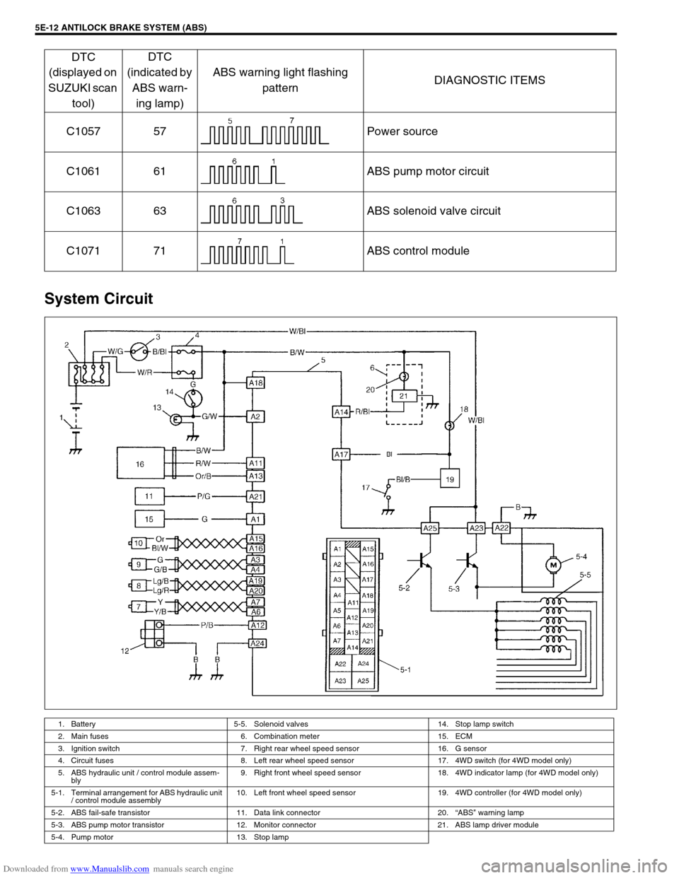
System Circuit
C1057 57 Power source
C1061 61 ABS pump motor circuit
C1063 63 ABS solenoid valve circuit
C1071 71 ABS control module
1. Battery 5-5. Solenoid valves 14. Stop lamp switch
2. Main fuses 6. Combination meter 15. ECM
3. Ignition switch 7. Right rear wheel speed sensor 16. G sensor
4. Circuit fuses 8. Left rear wheel speed sensor 17. 4WD switch (for 4WD model only)
5. ABS hydraulic unit / control module assem-
bly9. Right front wheel speed sensor 18. 4WD indicator lamp (for 4WD model only)
5-1. Terminal arrangement for ABS hydraulic unit
/ control module assembly10. Left front wheel speed sensor 19. 4WD controller (for 4WD model only)
5-2. ABS fail-safe transistor 11. Data link connector 20.“ABS” warning lamp
5-3. ABS pump motor transistor 12. Monitor connector 21. ABS lamp driver module
5-4. Pump motor 13. Stop lamp
DTC
(displayed on
SUZUKI scan
tool)DTC
(indicated by
ABS warn-
ing lamp)ABS warning light flashing
patternDIAGNOSTIC ITEMS
Page 331 of 687
Downloaded from www.Manualslib.com manuals search engine 5E-14 ANTILOCK BRAKE SYSTEM (ABS)
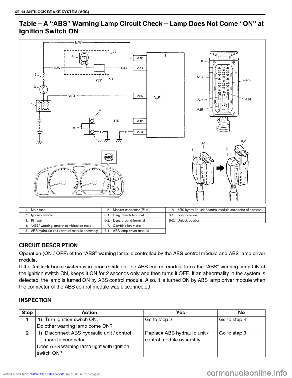
Table – A “ABS” Warning Lamp Circuit Check – Lamp Does Not Come “ON” at
Ignition Switch ON
CIRCUIT DESCRIPTION
Operation (ON / OFF) of the “ABS” warning lamp is controlled by the ABS control module and ABS lamp driver
module.
If the Antilock brake system is in good condition, the ABS control module turns the “ABS” warning lamp ON at
the ignition switch ON, keeps it ON for 2 seconds only and then turns it OFF. If an abnormality in the system is
detected, the lamp is turned ON by ABS control module. Also, it is turned ON by ABS lamp driver module when
the connector of the ABS control module was disconnected.
INSPECTION
1. Main fuse 6. Monitor connector (Blue) 8. ABS hydraulic unit / control module connector of harness
2. Ignition switch 6-1. Diag. switch terminal 8-1. Lock position
3. IG fuse 6-2. Diag. ground terminal 8-2. Unlock position
4.“ABS” warning lamp in combination meter 7. Combination meter
5. ABS hydraulic unit / control module assembly 7-1. ABS lamp driver module
Step Action Yes No
1 1) Turn ignition switch ON.
Do other warning lamp come ON?Go to step 2. Go to step 4.
2 1) Disconnect ABS hydraulic unit / control
module connector.
Does ABS warning lamp light with ignition
switch ON?Replace ABS hydraulic unit /
control module assembly.Go to step 3.
Page 332 of 687

Downloaded from www.Manualslib.com manuals search engine ANTILOCK BRAKE SYSTEM (ABS) 5E-15
Table – B “ABS” Warning Lamp Circuit Check – Lamp Comes “ON” Steady
Refer to TABLE – A for System Circuit Diagram and Circuit Description.
INSPECTION
3 1) Remove combination meter.
Is bulb of ABS warning lamp in good condition?“R/Bl” circuit shorted to ground.
If OK, replace ABS warning cir-
cuit (lamp driver module).Replace bulb.
4 Is IG fuse in good condition? Open in “B/W” wire to combina-
tion meter or poor connection.Repair and replace. Step Action Yes No
Step Action Yes No
1 Perform diagnostic trouble code check. Is there
any DTC (including code No.12, NO CODES on
SUZUKI scan tool) exists?Go to step 2. Go to step 3.
2 Is malfunction DTC (other than code No.12)
exists at step 1?Go to step 7 of ABS diag-
nostic flow table in this
section.Go to step 3.
3 1) Disconnect ABS hydraulic unit / control
module connector.
2) Check for proper connection to ABS hydrau-
lic unit / control module connector at termi-
nals “A14” and “A18”.
3) If OK, turn ignition switch “ON” and mea-
sure voltage at terminal “A18” of connector.
Is it 10 – 14 V?Go to step 4.“B/W” circuit open.
4 1) With ABS control module connector discon-
nected, turn ignition switch ON and light
ABS warning lamp.
2) Connect terminal “A14” of disconnected
connector to ground using service wire.
Does “ABS warning lamp” turn off?Go to step 5.“R/Bl” circuit open.
If wire and connection are
OK, replace ABS lamp
driver module.
5 1) Measure resistance from connector termi-
nal “A24” to body ground.
Is continuity indicated?Substitute a known-good
ABS hydraulic unit / con-
trol module assembly and
recheck.“B” circuit open.
Page 338 of 687
Downloaded from www.Manualslib.com manuals search engine ANTILOCK BRAKE SYSTEM (ABS) 5E-21
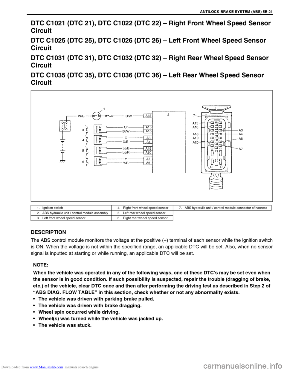
DTC C1021 (DTC 21), DTC C1022 (DTC 22) – Right Front Wheel Speed Sensor
Circuit
DTC C1025 (DTC 25), DTC C1026 (DTC 26) – Left Front Wheel Speed Sensor
Circuit
DTC C1031 (DTC 31), DTC C1032 (DTC 32) – Right Rear Wheel Speed Sensor
Circuit
DTC C1035 (DTC 35), DTC C1036 (DTC 36) – Left Rear Wheel Speed Sensor
Circuit
DESCRIPTION
The ABS control module monitors the voltage at the positive (+) terminal of each sensor while the ignition switch
is ON. When the voltage is not within the specified range, an applicable DTC will be set. Also, when no sensor
signal is inputted at starting or while running, an applicable DTC will be set.
1. Ignition switch 4. Right front wheel speed sensor 7. ABS hydraulic unit / control module connector of harness
2. ABS hydraulic unit / control module assembly 5. Left rear wheel speed sensor
3. Left front wheel speed sensor 6. Right rear wheel speed sensor
NOTE:
When the vehicle was operated in any of the following ways, one of these DTC’s may be set even when
the sensor is in good condition. If such possibility is suspected, repair the trouble (dragging of brake,
etc.) of the vehicle, clear DTC once and then after performing the driving test as described in Step 2 of
“ABS DIAG. FLOW TABLE” in this section, check whether or not any abnormality exists.
The vehicle was driven with parking brake pulled.
The vehicle was driven with brake dragging.
Wheel spin occurred while driving.
Wheel(s) was turned while the vehicle was jacked up.
The vehicle was stuck.
Page 351 of 687
Downloaded from www.Manualslib.com manuals search engine 5E-34 ANTILOCK BRAKE SYSTEM (ABS)
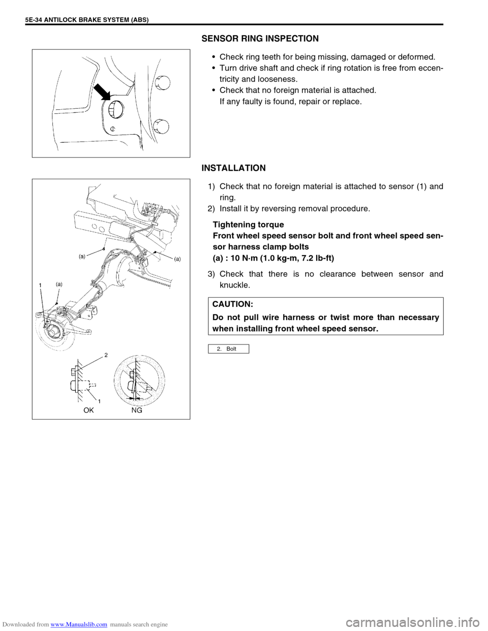
SENSOR RING INSPECTION
Check ring teeth for being missing, damaged or deformed.
Turn drive shaft and check if ring rotation is free from eccen-
tricity and looseness.
Check that no foreign material is attached.
If any faulty is found, repair or replace.
INSTALLATION
1) Check that no foreign material is attached to sensor (1) and
ring.
2) Install it by reversing removal procedure.
Tightening torque
Front wheel speed sensor bolt and front wheel speed sen-
sor harness clamp bolts
(a) : 10 N·m (1.0 kg-m, 7.2 lb-ft)
3) Check that there is no clearance between sensor and
knuckle.
CAUTION:
Do not pull wire harness or twist more than necessary
when installing front wheel speed sensor.
2. Bolt
Page 359 of 687

Downloaded from www.Manualslib.com manuals search engine 6-2 ENGINE GENERAL INFORMATION AND DIAGNOSIS
Diagnostic trouble code (DTC) table ......... 6-16
Fail-safe table............................................ 6-19
Visual inspection ....................................... 6-20
Engine basic inspection ............................ 6-21
Engine diagnosis table .............................. 6-23
Scan Tool Data ............................................. 6-28
Scan tool data definitions .......................... 6-30
Inspection of ECM and Its Circuits ................ 6-33
Component Location ..................................... 6-42
Table A-1 Malfunction Indicator Lamp Circuit
Check - Lamp Does Not Come “ON” at Ignition
Switch ON (But Engine at Stop).................... 6-43
Table A-2 Malfunction Indicator Lamp Circuit
Check - Lamp Remains “ON” after Engine
Starts............................................................. 6-44
Table A-3 Malfunction Indicator Lamp Circuit
Check - Mil Flashes at Ignition Switch ON .... 6-45
Table A-4 Malfunction Indicator Lamp Circuit
Check - MIL Does Not Flash, Just Remains
ON or Just Remains OFF Even with Grounding
Diagnosis Switch Terminal............................ 6-45
Table A-5 ECM Power and Ground Circuit
Check - MIL Doesn’t Light at Ignition Switch
ON and Engine Doesn’t Start Though It Is
Cranked Up ................................................... 6-46
DTC P0105 (DTC No.11) Manifold Absolute
Pressure (MAP) Circuit Malfunction .............. 6-48
DTC P0110 (DTC No.18) Intake Air Temp.
(IAT) Circuit Malfunction ............................... 6-51
DTC P0115 (DTC No.19) Engine Coolant
Temperature (ECT) Circuit Malfunction ........ 6-53
DTC P0120 (DTC No.13) Throttle Position
Circuit Malfunction ........................................ 6-55
DTC P0121 Throttle Position Circuit Range /
Performance Problem ................................... 6-57
DTC P0130 (DTC No.14) Heated Oxygen
Sensor (HO2S) Circuit Malfunction
(Sensor-1) ..................................................... 6-59
DTC P0133 Heated Oxygen Sensor (HO2S)
Circuit Slow Response (Sensor-1) ................ 6-61
DTC P0135 (DTC No.14) Heated Oxygen
Sensor (HO2S) Heater Circuit Malfunction
(Sensor-1) ..................................................... 6-62
DTC P0136 Heated Oxygen Sensor (HO2S)
Circuit Malfunction (Sensor-2) ...................... 6-64
DTC P0141 Heated Oxygen Sensor (HO2S)
Heater Circuit Malfunction (Sensor-2)........... 6-66
DTC P0171 Fuel System Too Lean .............. 6-68
DTC P0172 Fuel System Too Rich ............... 6-68
DTC P0300 Random Misfire Detected
(Misfire Detected at 2 or More Cylinders) ..... 6-72DTC P0301 Cylinder 1 Misfire Detected ........ 6-72
DTC P0302 Cylinder 2 Misfire Detected ........ 6-72
DTC P0303 Cylinder 3 Misfire Detected ........ 6-72
DTC P0304 Cylinder 4 Misfire Detected ........ 6-72
DTC P0325 (DTC No.17) Knock Sensor Circuit
Malfunction .................................................... 6-77
DTC P0335 (DTC No.23) Crankshaft Position
(CKP) Sensor Circuit Malfunction .................. 6-79
DTC P0340 (DTC No.15) Camshaft Position
(CMP) Sensor Circuit Malfunction ................. 6-82
DTC P0400 Exhaust Gas Recirculation Flow
Malfunction .................................................... 6-85
DTC P0420 Catalyst System Efficiency below
Threshold ....................................................... 6-88
DTC P0443 Purge Control Valve Circuit
Malfunction .................................................... 6-91
DTC P0481 A/C Condenser Fan Control
Circuit Malfunction ......................................... 6-92
DTC P0500 (DTC No.16) Vehicle Speed
Sensor (VSS) Malfunction ............................. 6-94
DTC P0505 Idle Control System
Malfunction .................................................... 6-96
DTC P0601 Internal Control Module Memory
Check Sum Error (DTC No.71) ...................... 6-98
DTC P1450 Barometric Pressure Sensor
Low / High Input ............................................. 6-99
DTC P1451 Barometric Pressure Sensor
Performance Problem .................................... 6-99
DTC P1500 Engine Starter Signal Circuit
Malfunction .................................................. 6-101
DTC P1510 ECM Back-up Power Supply
Malfunction .................................................. 6-103
DTC P1570 (DTC No.21) ABS Signal Circuit
Malfunction .................................................. 6-104
DTC P1600 Serial Communication Problem
Between ECM and TCM .............................. 6-105
DTC P1717 A/T Drive Range (Park / Neutral
Position) Signal Circuit Malfunction ............. 6-107
Table B-1 Fuel Injector Circuit Check ..........6-109
Table B-2 Fuel Pump and Its Circuit
Check........................................................... 6-110
Table B-3 Fuel Pressure Check................... 6-112
Table B-4 Idle Air Control System Check ....6-114
Table B-5 A/C Signal Circuits Check
(Vehicle with A/C) ........................................ 6-117
Table B-6 Electric Load Signal Circuit
Check........................................................... 6-119
TAble B-7 A/C Condenser Fan Control
System Check.............................................. 6-121
Special Tool ................................................... 6-123
Page 362 of 687
Downloaded from www.Manualslib.com manuals search engine ENGINE GENERAL INFORMATION AND DIAGNOSIS 6-5
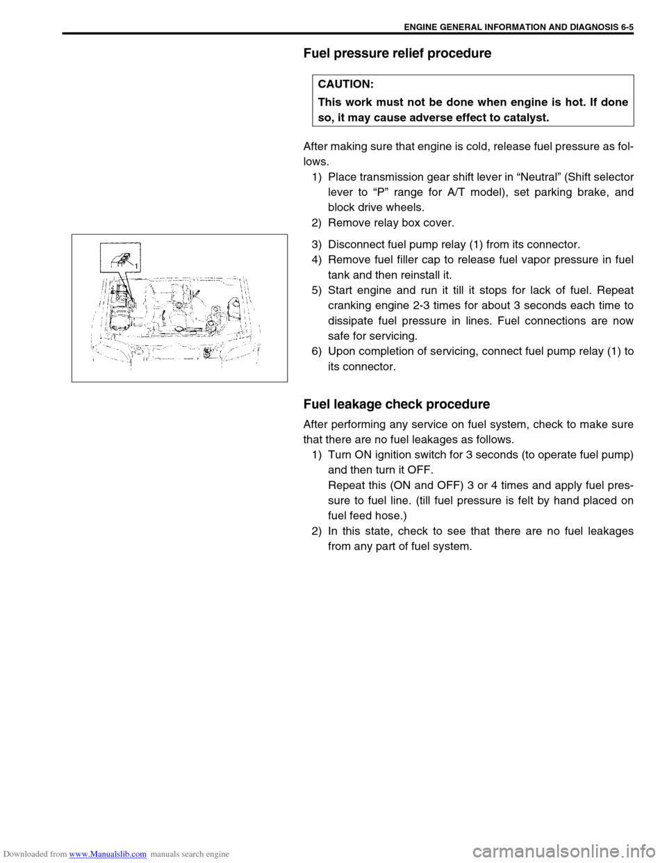
Fuel pressure relief procedure
After making sure that engine is cold, release fuel pressure as fol-
lows.
1) Place transmission gear shift lever in “Neutral” (Shift selector
lever to “P” range for A/T model), set parking brake, and
block drive wheels.
2) Remove relay box cover.
3) Disconnect fuel pump relay (1) from its connector.
4) Remove fuel filler cap to release fuel vapor pressure in fuel
tank and then reinstall it.
5) Start engine and run it till it stops for lack of fuel. Repeat
cranking engine 2-3 times for about 3 seconds each time to
dissipate fuel pressure in lines. Fuel connections are now
safe for servicing.
6) Upon completion of servicing, connect fuel pump relay (1) to
its connector.
Fuel leakage check procedure
After performing any service on fuel system, check to make sure
that there are no fuel leakages as follows.
1) Turn ON ignition switch for 3 seconds (to operate fuel pump)
and then turn it OFF.
Repeat this (ON and OFF) 3 or 4 times and apply fuel pres-
sure to fuel line. (till fuel pressure is felt by hand placed on
fuel feed hose.)
2) In this state, check to see that there are no fuel leakages
from any part of fuel system. CAUTION:
This work must not be done when engine is hot. If done
so, it may cause adverse effect to catalyst.
Page 366 of 687
Downloaded from www.Manualslib.com manuals search engine ENGINE GENERAL INFORMATION AND DIAGNOSIS 6-9
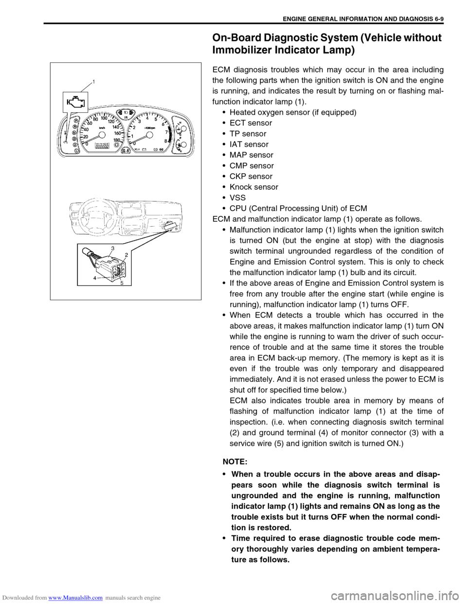
On-Board Diagnostic System (Vehicle without
Immobilizer Indicator Lamp)
ECM diagnosis troubles which may occur in the area including
the following parts when the ignition switch is ON and the engine
is running, and indicates the result by turning on or flashing mal-
function indicator lamp (1).
Heated oxygen sensor (if equipped)
ECT sensor
TP sensor
IAT sensor
MAP sensor
CMP sensor
CKP sensor
Knock sensor
VSS
CPU (Central Processing Unit) of ECM
ECM and malfunction indicator lamp (1) operate as follows.
Malfunction indicator lamp (1) lights when the ignition switch
is turned ON (but the engine at stop) with the diagnosis
switch terminal ungrounded regardless of the condition of
Engine and Emission Control system. This is only to check
the malfunction indicator lamp (1) bulb and its circuit.
If the above areas of Engine and Emission Control system is
free from any trouble after the engine start (while engine is
running), malfunction indicator lamp (1) turns OFF.
When ECM detects a trouble which has occurred in the
above areas, it makes malfunction indicator lamp (1) turn ON
while the engine is running to warn the driver of such occur-
rence of trouble and at the same time it stores the trouble
area in ECM back-up memory. (The memory is kept as it is
even if the trouble was only temporary and disappeared
immediately. And it is not erased unless the power to ECM is
shut off for specified time below.)
ECM also indicates trouble area in memory by means of
flashing of malfunction indicator lamp (1) at the time of
inspection. (i.e. when connecting diagnosis switch terminal
(2) and ground terminal (4) of monitor connector (3) with a
service wire (5) and ignition switch is turned ON.)
NOTE:
When a trouble occurs in the above areas and disap-
pears soon while the diagnosis switch terminal is
ungrounded and the engine is running, malfunction
indicator lamp (1) lights and remains ON as long as the
trouble exists but it turns OFF when the normal condi-
tion is restored.
Time required to erase diagnostic trouble code mem-
ory thoroughly varies depending on ambient tempera-
ture as follows.