turn SUZUKI JIMNY 2005 3.G Service Repair Manual
[x] Cancel search | Manufacturer: SUZUKI, Model Year: 2005, Model line: JIMNY, Model: SUZUKI JIMNY 2005 3.GPages: 687, PDF Size: 13.38 MB
Page 284 of 687
Downloaded from www.Manualslib.com manuals search engine BRAKES 5-23
INSPECTION
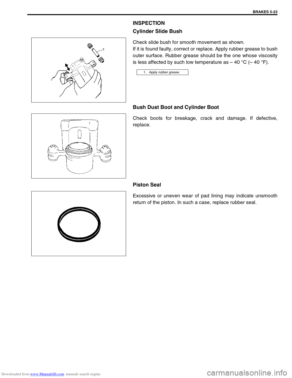
Cylinder Slide Bush
Check slide bush for smooth movement as shown.
If it is found faulty, correct or replace. Apply rubber grease to bush
outer surface. Rubber grease should be the one whose viscosity
is less affected by such low temperature as – 40 °C (– 40 °F).
Bush Dust Boot and Cylinder Boot
Check boots for breakage, crack and damage. If defective,
replace.
Piston Seal
Excessive or uneven wear of pad lining may indicate unsmooth
return of the piston. In such a case, replace rubber seal.
1. Apply rubber grease
Page 290 of 687
Downloaded from www.Manualslib.com manuals search engine BRAKES 5-29
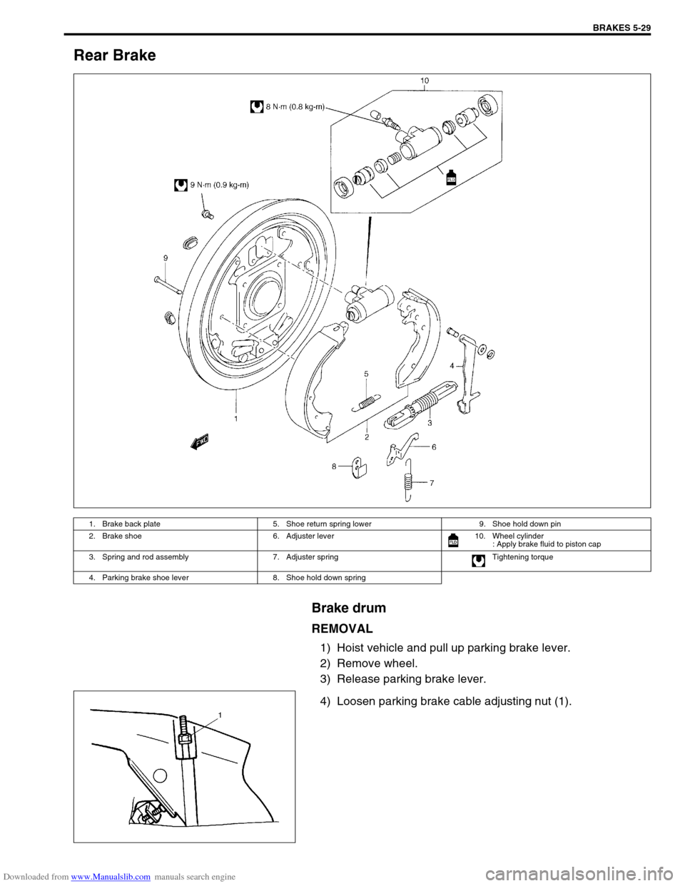
Rear Brake
Brake drum
REMOVAL
1) Hoist vehicle and pull up parking brake lever.
2) Remove wheel.
3) Release parking brake lever.
4) Loosen parking brake cable adjusting nut (1).
1. Brake back plate 5. Shoe return spring lower 9. Shoe hold down pin
2. Brake shoe 6. Adjuster lever 10. Wheel cylinder
: Apply brake fluid to piston cap
3. Spring and rod assembly 7. Adjuster spring Tightening torque
4. Parking brake shoe lever 8. Shoe hold down spring
Page 291 of 687
Downloaded from www.Manualslib.com manuals search engine 5-30 BRAKES
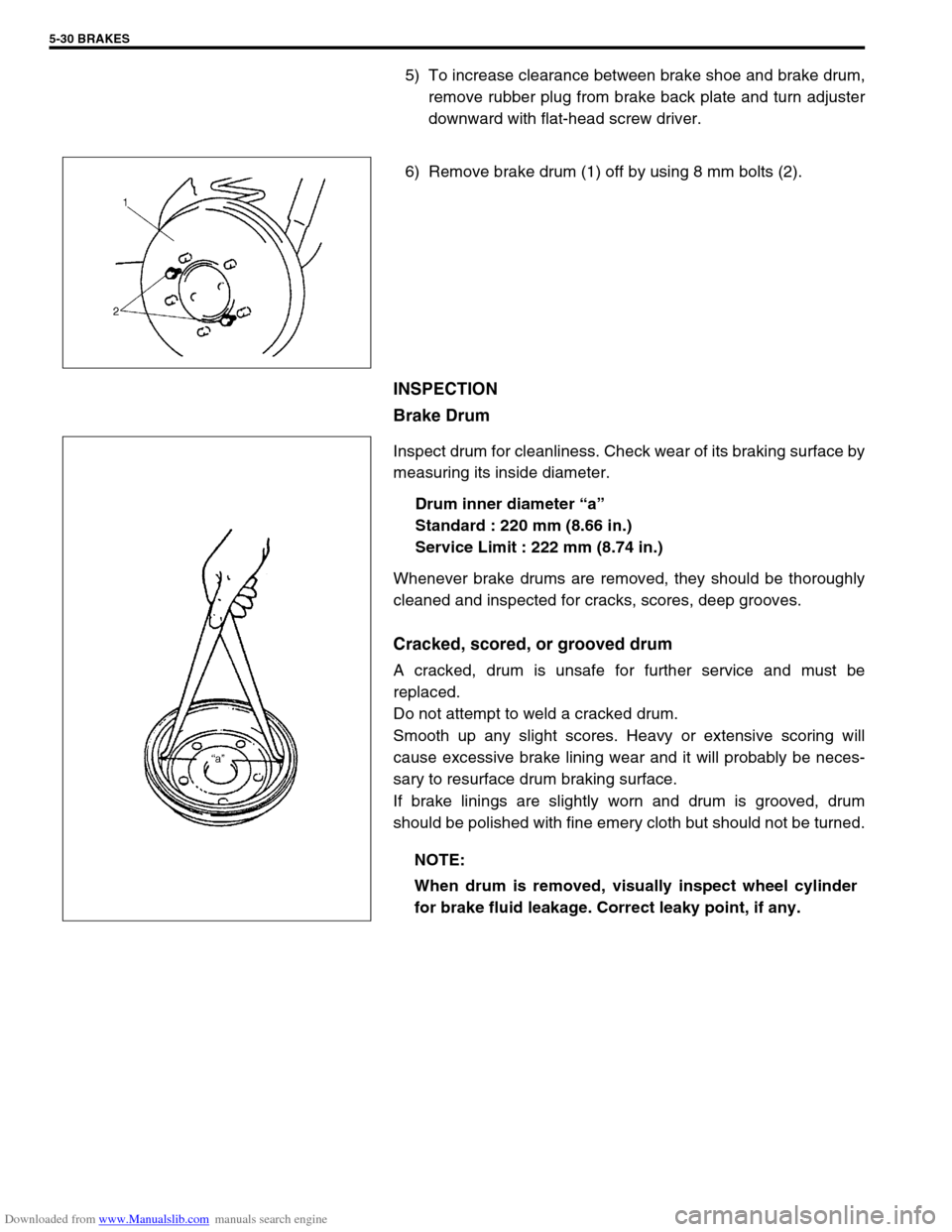
5) To increase clearance between brake shoe and brake drum,
remove rubber plug from brake back plate and turn adjuster
downward with flat-head screw driver.
6) Remove brake drum (1) off by using 8 mm bolts (2).
INSPECTION
Brake Drum
Inspect drum for cleanliness. Check wear of its braking surface by
measuring its inside diameter.
Drum inner diameter “a”
Standard : 220 mm (8.66 in.)
Service Limit : 222 mm (8.74 in.)
Whenever brake drums are removed, they should be thoroughly
cleaned and inspected for cracks, scores, deep grooves.
Cracked, scored, or grooved drum
A cracked, drum is unsafe for further service and must be
replaced.
Do not attempt to weld a cracked drum.
Smooth up any slight scores. Heavy or extensive scoring will
cause excessive brake lining wear and it will probably be neces-
sary to resurface drum braking surface.
If brake linings are slightly worn and drum is grooved, drum
should be polished with fine emery cloth but should not be turned.
NOTE:
When drum is removed, visually inspect wheel cylinder
for brake fluid leakage. Correct leaky point, if any.
Page 292 of 687
Downloaded from www.Manualslib.com manuals search engine BRAKES 5-31
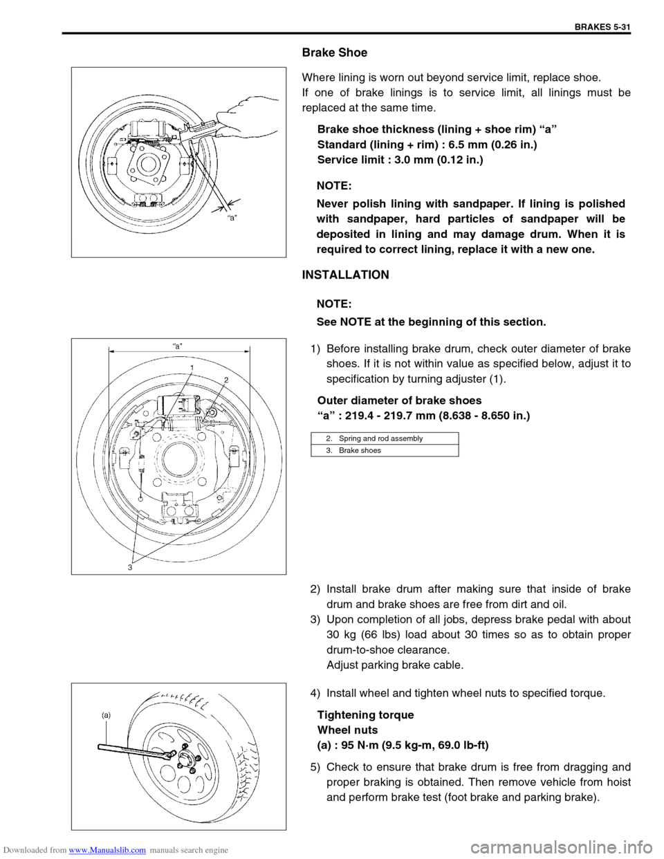
Brake Shoe
Where lining is worn out beyond service limit, replace shoe.
If one of brake linings is to service limit, all linings must be
replaced at the same time.
Brake shoe thickness (lining + shoe rim) “a”
Standard (lining + rim) : 6.5 mm (0.26 in.)
Service limit : 3.0 mm (0.12 in.)
INSTALLATION
1) Before installing brake drum, check outer diameter of brake
shoes. If it is not within value as specified below, adjust it to
specification by turning adjuster (1).
Outer diameter of brake shoes
“a” : 219.4 - 219.7 mm (8.638 - 8.650 in.)
2) Install brake drum after making sure that inside of brake
drum and brake shoes are free from dirt and oil.
3) Upon completion of all jobs, depress brake pedal with about
30 kg (66 lbs) load about 30 times so as to obtain proper
drum-to-shoe clearance.
Adjust parking brake cable.
4) Install wheel and tighten wheel nuts to specified torque.
Tightening torque
Wheel nuts
(a) : 95 N·m (9.5 kg-m, 69.0 lb-ft)
5) Check to ensure that brake drum is free from dragging and
proper braking is obtained. Then remove vehicle from hoist
and perform brake test (foot brake and parking brake). NOTE:
Never polish lining with sandpaper. If lining is polished
with sandpaper, hard particles of sandpaper will be
deposited in lining and may damage drum. When it is
required to correct lining, replace it with a new one.
NOTE:
See NOTE at the beginning of this section.
2. Spring and rod assembly
3. Brake shoes
Page 293 of 687
Downloaded from www.Manualslib.com manuals search engine 5-32 BRAKES
Brake shoe
REMOVAL
1) Remove brake drum referring to “Brake Drum” in this sec-
tion.
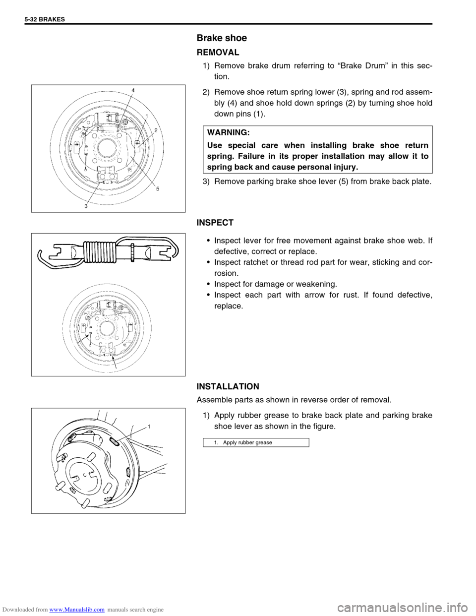
2) Remove shoe return spring lower (3), spring and rod assem-
bly (4) and shoe hold down springs (2) by turning shoe hold
down pins (1).
3) Remove parking brake shoe lever (5) from brake back plate.
INSPECT
Inspect lever for free movement against brake shoe web. If
defective, correct or replace.
Inspect ratchet or thread rod part for wear, sticking and cor-
rosion.
Inspect for damage or weakening.
Inspect each part with arrow for rust. If found defective,
replace.
INSTALLATION
Assemble parts as shown in reverse order of removal.
1) Apply rubber grease to brake back plate and parking brake
shoe lever as shown in the figure. WARNING:
Use special care when installing brake shoe return
spring. Failure in its proper installation may allow it to
spring back and cause personal injury.
1. Apply rubber grease
Page 294 of 687
Downloaded from www.Manualslib.com manuals search engine BRAKES 5-33
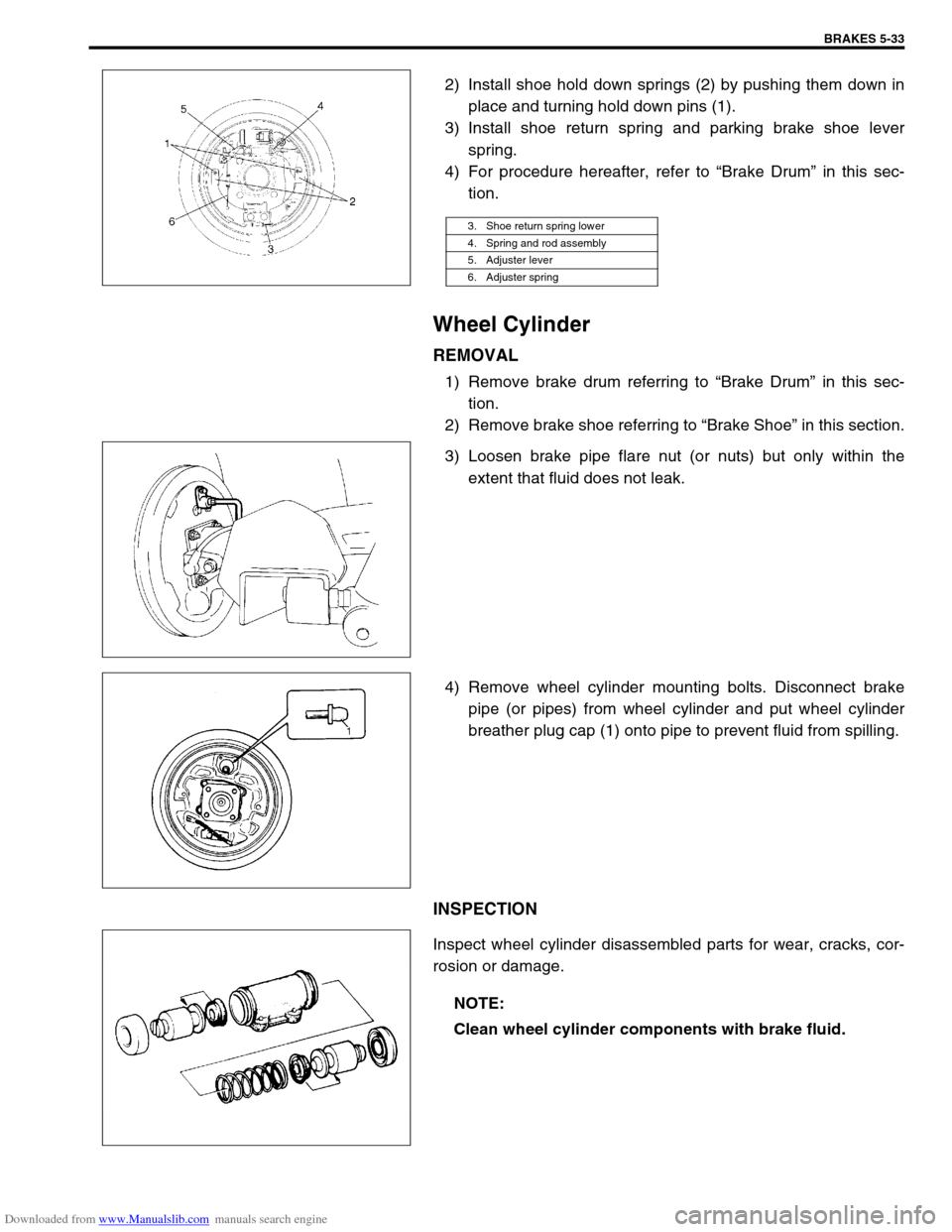
2) Install shoe hold down springs (2) by pushing them down in
place and turning hold down pins (1).
3) Install shoe return spring and parking brake shoe lever
spring.
4) For procedure hereafter, refer to “Brake Drum” in this sec-
tion.
Wheel Cylinder
REMOVAL
1) Remove brake drum referring to “Brake Drum” in this sec-
tion.
2) Remove brake shoe referring to “Brake Shoe” in this section.
3) Loosen brake pipe flare nut (or nuts) but only within the
extent that fluid does not leak.
4) Remove wheel cylinder mounting bolts. Disconnect brake
pipe (or pipes) from wheel cylinder and put wheel cylinder
breather plug cap (1) onto pipe to prevent fluid from spilling.
INSPECTION
Inspect wheel cylinder disassembled parts for wear, cracks, cor-
rosion or damage.
3. Shoe return spring lower
4. Spring and rod assembly
5. Adjuster lever
6. Adjuster spring
NOTE:
Clean wheel cylinder components with brake fluid.
Page 299 of 687
Downloaded from www.Manualslib.com manuals search engine 5-38 BRAKES
INSTALLATION
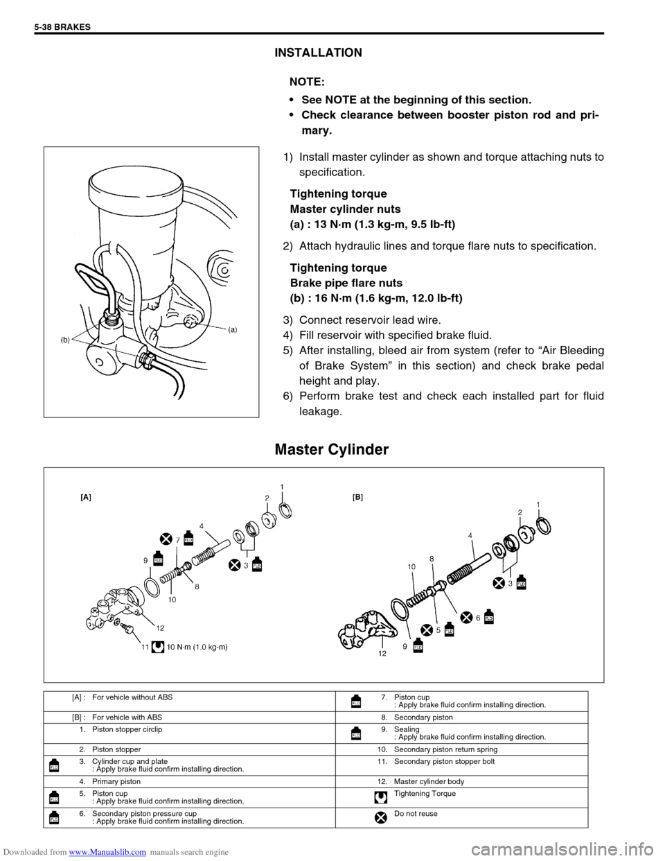
1) Install master cylinder as shown and torque attaching nuts to
specification.
Tightening torque
Master cylinder nuts
(a) : 13 N·m (1.3 kg-m, 9.5 Ib-ft)
2) Attach hydraulic lines and torque flare nuts to specification.
Tightening torque
Brake pipe flare nuts
(b) : 16 N·m (1.6 kg-m, 12.0 lb-ft)
3) Connect reservoir lead wire.
4) Fill reservoir with specified brake fluid.
5) After installing, bleed air from system (refer to “Air Bleeding
of Brake System” in this section) and check brake pedal
height and play.
6) Perform brake test and check each installed part for fluid
leakage.
Master Cylinder
NOTE:
See NOTE at the beginning of this section.
Check clearance between booster piston rod and pri-
mary.
[A] : For vehicle without ABS 7. Piston cup
: Apply brake fluid confirm installing direction.
[B] : For vehicle with ABS 8. Secondary piston
1. Piston stopper circlip 9. Sealing
: Apply brake fluid confirm installing direction.
2. Piston stopper 10. Secondary piston return spring
3. Cylinder cup and plate
: Apply brake fluid confirm installing direction.11. Secondary piston stopper bolt
4. Primary piston 12. Master cylinder body
5. Piston cup
: Apply brake fluid confirm installing direction.Tightening Torque
6. Secondary piston pressure cup
: Apply brake fluid confirm installing direction.Do not reuse
Page 308 of 687
Downloaded from www.Manualslib.com manuals search engine BRAKES 5-47
CLEARANCE BETWEEN BOOSTER PISTON ROD AND
MASTER CYLINDER PISTON
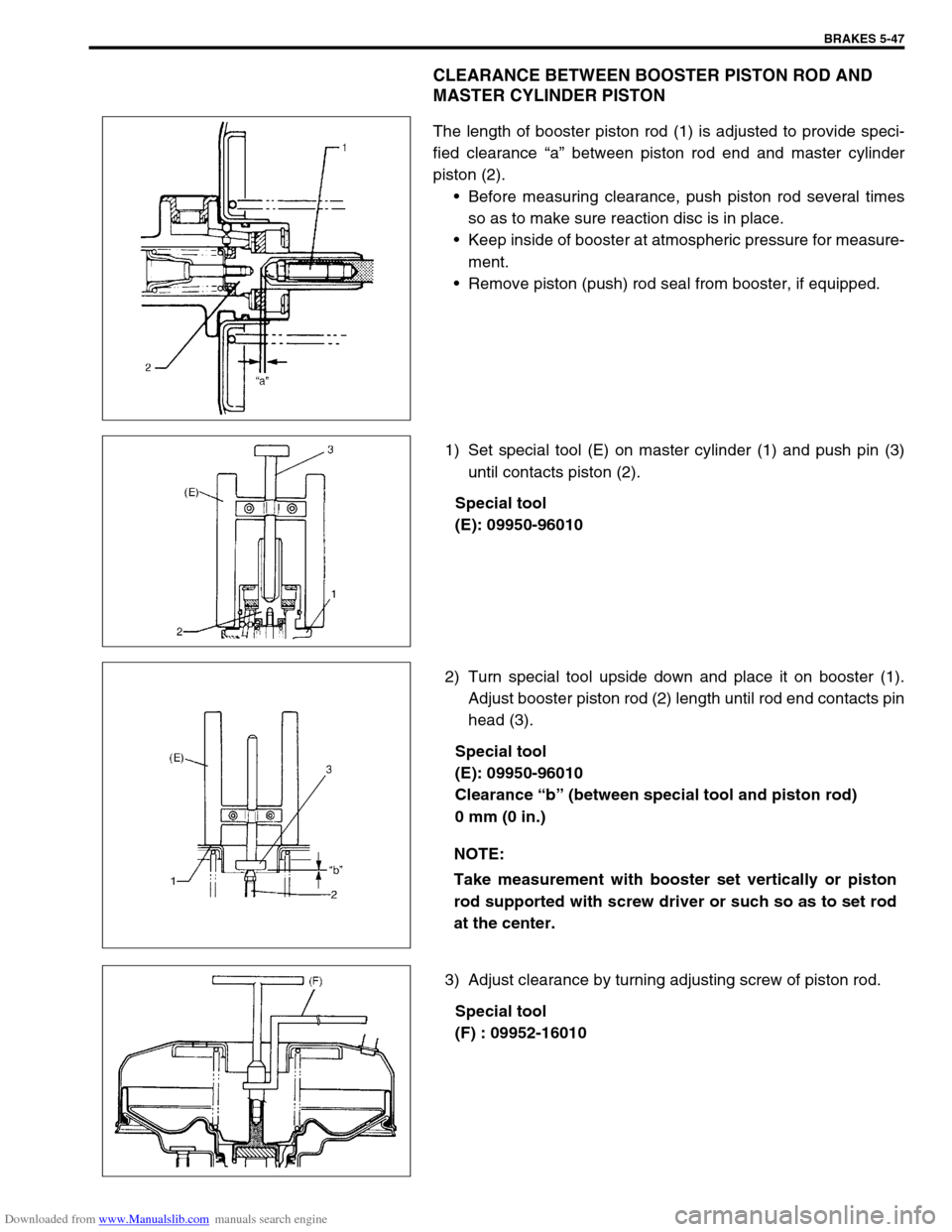
The length of booster piston rod (1) is adjusted to provide speci-
fied clearance “a” between piston rod end and master cylinder
piston (2).
Before measuring clearance, push piston rod several times
so as to make sure reaction disc is in place.
Keep inside of booster at atmospheric pressure for measure-
ment.
Remove piston (push) rod seal from booster, if equipped.
1) Set special tool (E) on master cylinder (1) and push pin (3)
until contacts piston (2).
Special tool
(E): 09950-96010
2) Turn special tool upside down and place it on booster (1).
Adjust booster piston rod (2) length until rod end contacts pin
head (3).
Special tool
(E): 09950-96010
Clearance “b” (between special tool and piston rod)
0 mm (0 in.)
3) Adjust clearance by turning adjusting screw of piston rod.
Special tool
(F) : 09952-16010
NOTE:
Take measurement with booster set vertically or piston
rod supported with screw driver or such so as to set rod
at the center.
Page 311 of 687

Downloaded from www.Manualslib.com manuals search engine 5-50 BRAKES
REMOVAL
1) Raise, suitably support vehicle. Remove wheel if necessary.
2) Clean dirt and foreign material from both hose end or pipe end fittings. Remove brake hose and pipe.
INSTALLATION
1) Install brake hose and pipe by reversing removal procedure, noting the following points.
For installation, make sure that steering wheel is in straightforward position and hose has no twist or kink.
Check to make sure that hose doesn’t contact any part of suspension, both in extreme right and extreme left
turn conditions. If it does at any point, remove and correct. Fill and maintain brake fluid level in reservoir.
Bleed brake system.
2) Perform brake test and check installed part for fluid leakage.
Page 322 of 687
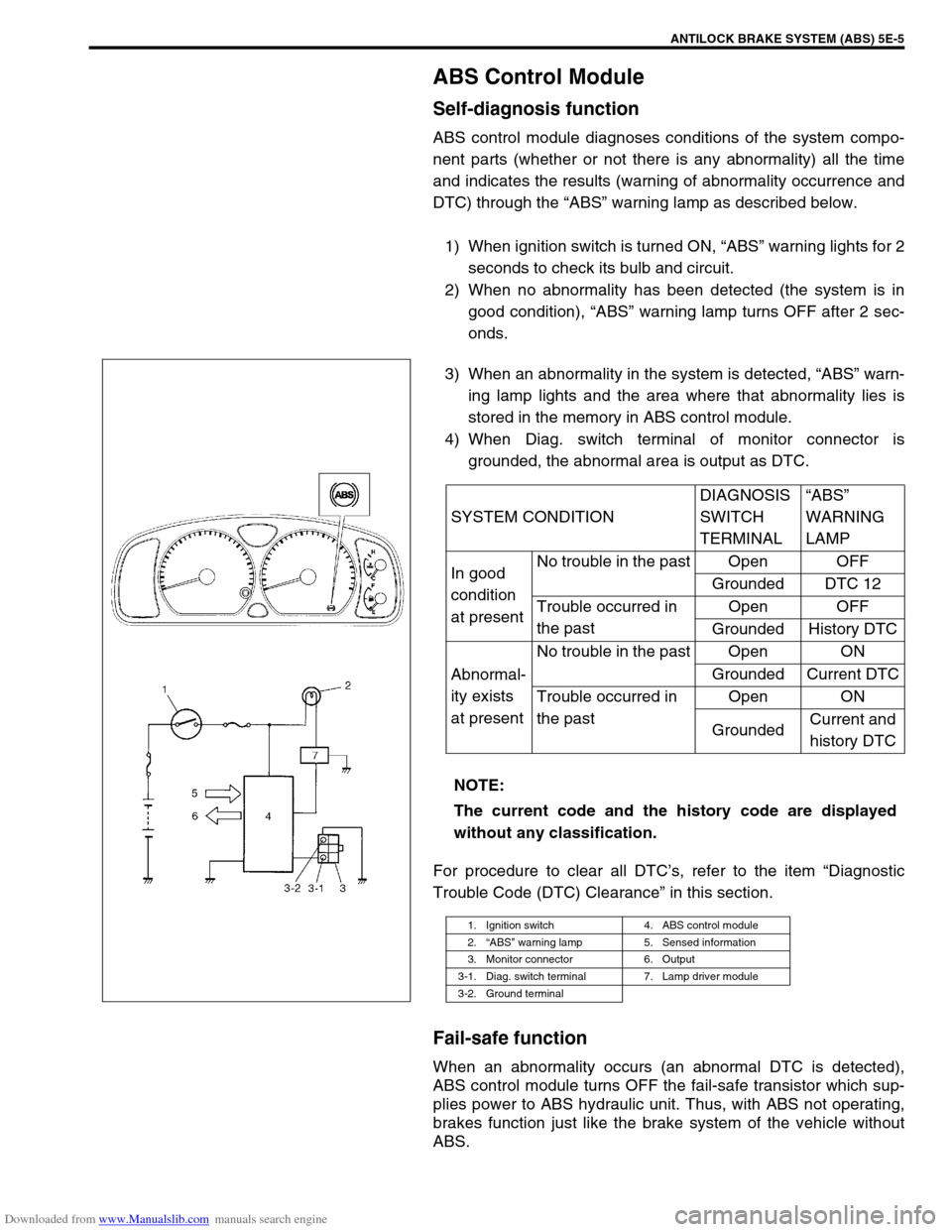
Downloaded from www.Manualslib.com manuals search engine ANTILOCK BRAKE SYSTEM (ABS) 5E-5
ABS Control Module
Self-diagnosis function
ABS control module diagnoses conditions of the system compo-
nent parts (whether or not there is any abnormality) all the time
and indicates the results (warning of abnormality occurrence and
DTC) through the “ABS” warning lamp as described below.
1) When ignition switch is turned ON, “ABS” warning lights for 2
seconds to check its bulb and circuit.
2) When no abnormality has been detected (the system is in
good condition), “ABS” warning lamp turns OFF after 2 sec-
onds.
3) When an abnormality in the system is detected, “ABS” warn-
ing lamp lights and the area where that abnormality lies is
stored in the memory in ABS control module.
4) When Diag. switch terminal of monitor connector is
grounded, the abnormal area is output as DTC.
For procedure to clear all DTC’s, refer to the item “Diagnostic
Trouble Code (DTC) Clearance” in this section.
Fail-safe function
When an abnormality occurs (an abnormal DTC is detected),
ABS control module turns OFF the fail-safe transistor which sup-
plies power to ABS hydraulic unit. Thus, with ABS not operating,
brakes function just like the brake system of the vehicle without
ABS.SYSTEM CONDITIONDIAGNOSIS
SWITCH
TERMINAL“ABS”
WARNING
LAMP
In good
condition
at presentNo trouble in the past Open OFF
Grounded DTC 12
Trouble occurred in
the pastOpen OFF
Grounded History DTC
Abnormal-
ity exists
at presentNo trouble in the past Open ON
Grounded Current DTC
Trouble occurred in
the pastOpen ON
GroundedCurrent and
history DTC
NOTE:
The current code and the history code are displayed
without any classification.
1. Ignition switch 4. ABS control module
2.“ABS” warning lamp 5. Sensed information
3. Monitor connector 6. Output
3-1. Diag. switch terminal 7. Lamp driver module
3-2. Ground terminal