valve SUZUKI JIMNY 2005 3.G Service Repair Manual
[x] Cancel search | Manufacturer: SUZUKI, Model Year: 2005, Model line: JIMNY, Model: SUZUKI JIMNY 2005 3.GPages: 687, PDF Size: 13.38 MB
Page 310 of 687
![SUZUKI JIMNY 2005 3.G Service Repair Manual Downloaded from www.Manualslib.com manuals search engine BRAKES 5-49
For right-hand steering vehicle
[A] : For vehicle without ABS X : View X 5. Brake caliper 12. To front left brake caliper
[B] : For SUZUKI JIMNY 2005 3.G Service Repair Manual Downloaded from www.Manualslib.com manuals search engine BRAKES 5-49
For right-hand steering vehicle
[A] : For vehicle without ABS X : View X 5. Brake caliper 12. To front left brake caliper
[B] : For](/img/20/7588/w960_7588-309.png)
Downloaded from www.Manualslib.com manuals search engine BRAKES 5-49
For right-hand steering vehicle
[A] : For vehicle without ABS X : View X 5. Brake caliper 12. To front left brake caliper
[B] : For vehicle with ABS Y : View Y 6. 4 way joint 13. To rear brake
F : Front side Z : View Z 7. 5 way joint 14. Front brake master cylinder
R : Right side 1. E-ring 8. ABS hydraulic unit a-f: Clamp
T : Top side 2. Flexible hose 9. P valve Tightening torque
V : View V 3. Hose washer 10. Hose bracket
W : View W 4. Hose bolt 11. To front right brake caliper
Page 315 of 687

Downloaded from www.Manualslib.com manuals search engine 5-54 BRAKES
Tightening Torque Specifications
Required Service Material
Fastening partTightening torque
Nm kg-m lb-ft
Brake caliper carrier bolt 85 8.5 61.5
Brake caliper pin bolt 22 2.2 16.0
Front brake flexible hose bolt 23 2.3 17.0
Rear brake back plate nut 23 2.3 17.0
Master cylinder nut 13 1.3 9.5
Booster nut 13 1.3 9.5
Brake pipe 5-way 4-way joint bolt 11 1.1 8.0
Brake pipe flare nut 16 1.6 12.0
LSPV bolt/P valve bolt 25 2.5 18.0
Brake bleeder plugFront caliper 11 1.1 8.0
Rear wheel cylinder, LSPV 8 0.8 6.0
Wheel nut 95 9.5 69.0
Hose bracket bolt 11 1.1 8.0
Booster clevis nut 25 2.5 18.0
Stop light switch lock nut 6.5 0.65 4.7
Parking brake lever bolt 23 2.3 17.0
Wheel cylinder mounting bolt 9 0.9 6.5
Piston stopper bolt 10 1.0 7.5
LSPV adjust bolt 25 2.5 18.0
Material Recommended SUZUKI products Use
Brake fluid Indicated on reservoir tank cap or
described in owner’s manual of vehi-
cleTo fill master cylinder reservoir.
To clean and apply to inner parts of master
cylinder caliper and wheel cylinder when they
are disassembled.
Water tight sealant SEALING COMPOUND 366E
99000-31090To apply to mating surfaces of brake back
plate and rear wheel cylinder.
Sealant SUZUKI BOND NO. 1215
99000-31110To apply to mating surfaces of brake back
plate and rear axle housing.
To apply to mating surfaces of brake back
plate and rear wheel bearing retainer.
Page 319 of 687
Downloaded from www.Manualslib.com manuals search engine 5E-2 ANTILOCK BRAKE SYSTEM (ABS)
General Description
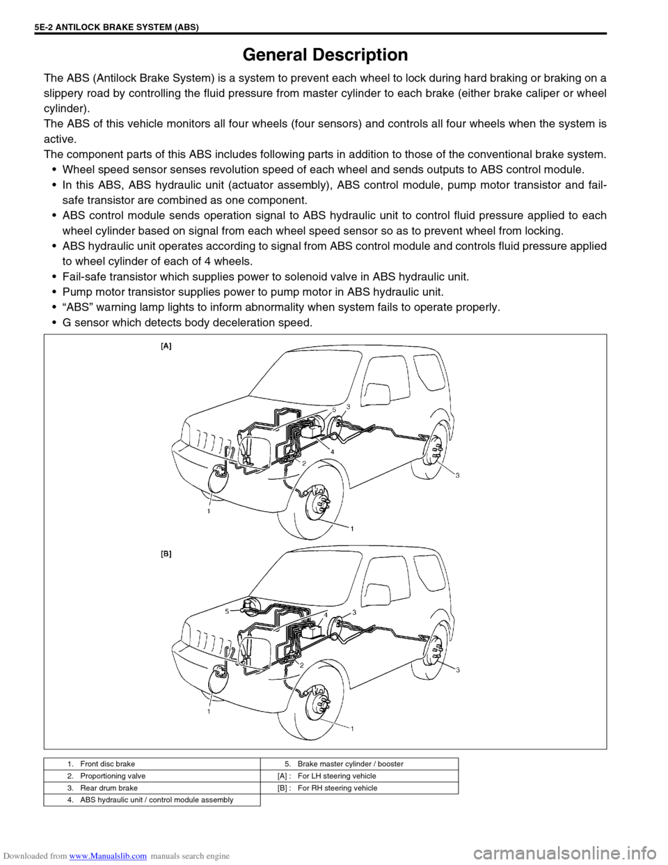
The ABS (Antilock Brake System) is a system to prevent each wheel to lock during hard braking or braking on a
slippery road by controlling the fluid pressure from master cylinder to each brake (either brake caliper or wheel
cylinder).
The ABS of this vehicle monitors all four wheels (four sensors) and controls all four wheels when the system is
active.
The component parts of this ABS includes following parts in addition to those of the conventional brake system.
Wheel speed sensor senses revolution speed of each wheel and sends outputs to ABS control module.
In this ABS, ABS hydraulic unit (actuator assembly), ABS control module, pump motor transistor and fail-
safe transistor are combined as one component.
ABS control module sends operation signal to ABS hydraulic unit to control fluid pressure applied to each
wheel cylinder based on signal from each wheel speed sensor so as to prevent wheel from locking.
ABS hydraulic unit operates according to signal from ABS control module and controls fluid pressure applied
to wheel cylinder of each of 4 wheels.
Fail-safe transistor which supplies power to solenoid valve in ABS hydraulic unit.
Pump motor transistor supplies power to pump motor in ABS hydraulic unit.
“ABS” warning lamp lights to inform abnormality when system fails to operate properly.
G sensor which detects body deceleration speed.
1. Front disc brake 5. Brake master cylinder / booster
2. Proportioning valve [A] : For LH steering vehicle
3. Rear drum brake [B] : For RH steering vehicle
4. ABS hydraulic unit / control module assembly
Page 320 of 687
Downloaded from www.Manualslib.com manuals search engine ANTILOCK BRAKE SYSTEM (ABS) 5E-3
System Schematic
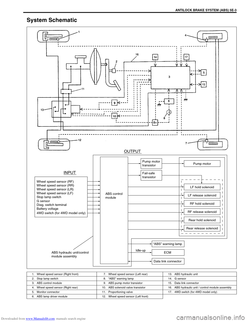
1. Wheel speed sensor (Right front) 7. Wheel speed sensor (Left rear) 13. ABS hydraulic unit
2. Stop lamp switch 8.“ABS” warning lamp 14. G sensor
3. ABS control module 9. ABS pump motor transistor 15. Data link connector
4. Wheel speed sensor (Right rear) 10. ABS solenoid valve transistor 16. ABS hydraulic unit / control module assembly
5. Monitor connector 11. Proportioning valve 17. 4WD switch (for 4WD model only)
6. ABS lamp driver module 12. Wheel speed sensor (Left front)
INPUTOUTPUT
ABS control
module Wheel speed sensor (RF)
Wheel speed sensor (RR)
Wheel speed sensor (LR)
Wheel speed sensor (LF)
Stop lamp switch
Diag. switch terminal
Battery voltage
4WD switch (for 4WD model only) G sensor
Pump motor
transistor
Fail-safe
transistor
Pump motor
LF hold solenoid
LF release solenoid
RF hold solenoid
RF release solenoid
Rear hold solenoid
Rear release solenoid
“ABS” warning lamp
Idle-up
ECM
Data link connector
ABS hydraulic unit/control
module assembly
Page 321 of 687
Downloaded from www.Manualslib.com manuals search engine 5E-4 ANTILOCK BRAKE SYSTEM (ABS)
ABS Component Parts Location
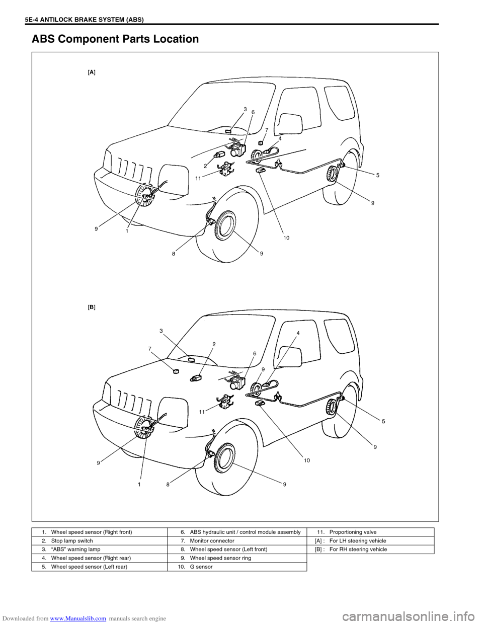
1. Wheel speed sensor (Right front) 6. ABS hydraulic unit / control module assembly 11. Proportioning valve
2. Stop lamp switch 7. Monitor connector [A] : For LH steering vehicle
3.“ABS” warning lamp 8. Wheel speed sensor (Left front) [B] : For RH steering vehicle
4. Wheel speed sensor (Right rear) 9. Wheel speed sensor ring
5. Wheel speed sensor (Left rear) 10. G sensor
Page 328 of 687
Downloaded from www.Manualslib.com manuals search engine ANTILOCK BRAKE SYSTEM (ABS) 5E-11
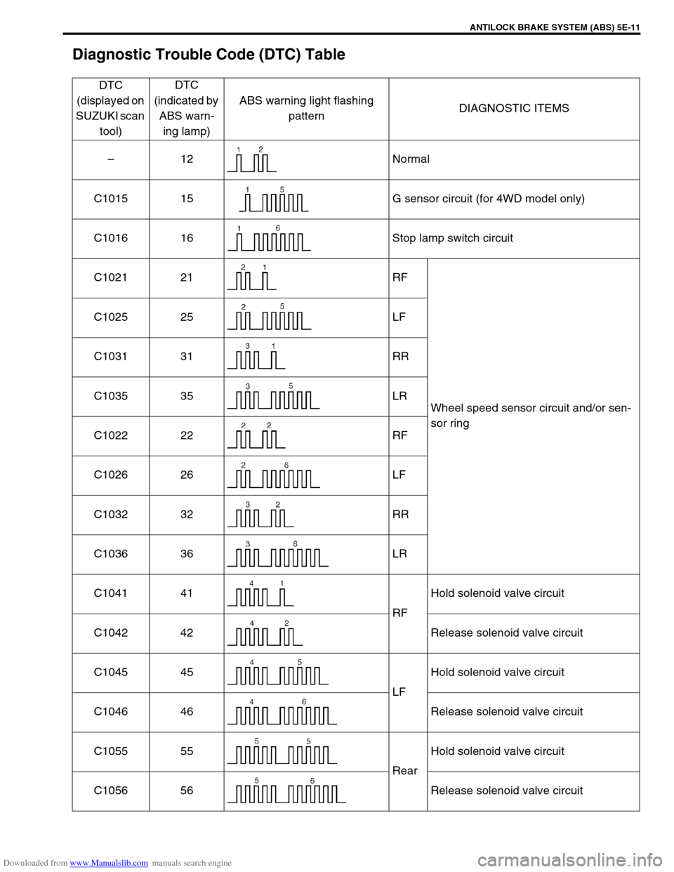
Diagnostic Trouble Code (DTC) Table
DTC
(displayed on
SUZUKI scan
tool)DTC
(indicated by
ABS warn-
ing lamp)ABS warning light flashing
patternDIAGNOSTIC ITEMS
–12 Normal
C1015 15 G sensor circuit (for 4WD model only)
C1016 16 Stop lamp switch circuit
C1021 21 RF
Wheel speed sensor circuit and/or sen-
sor ring C1025 25 LF
C1031 31 RR
C1035 35 LR
C1022 22 RF
C1026 26 LF
C1032 32 RR
C1036 36 LR
C1041 41
RFHold solenoid valve circuit
C1042 42 Release solenoid valve circuit
C1045 45
LFHold solenoid valve circuit
C1046 46 Release solenoid valve circuit
C1055 55
RearHold solenoid valve circuit
C1056 56 Release solenoid valve circuit
Page 329 of 687
Downloaded from www.Manualslib.com manuals search engine 5E-12 ANTILOCK BRAKE SYSTEM (ABS)
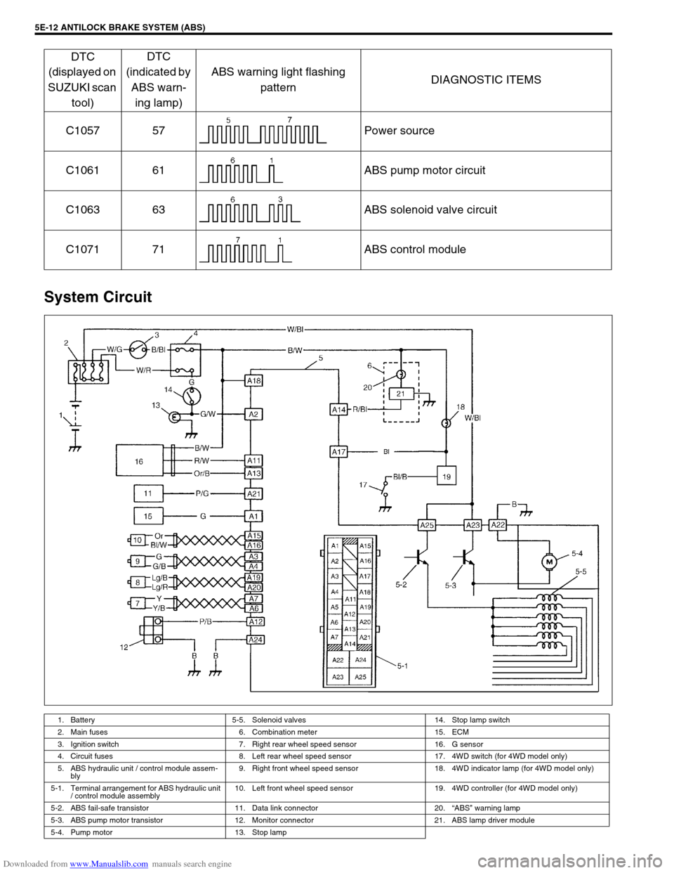
System Circuit
C1057 57 Power source
C1061 61 ABS pump motor circuit
C1063 63 ABS solenoid valve circuit
C1071 71 ABS control module
1. Battery 5-5. Solenoid valves 14. Stop lamp switch
2. Main fuses 6. Combination meter 15. ECM
3. Ignition switch 7. Right rear wheel speed sensor 16. G sensor
4. Circuit fuses 8. Left rear wheel speed sensor 17. 4WD switch (for 4WD model only)
5. ABS hydraulic unit / control module assem-
bly9. Right front wheel speed sensor 18. 4WD indicator lamp (for 4WD model only)
5-1. Terminal arrangement for ABS hydraulic unit
/ control module assembly10. Left front wheel speed sensor 19. 4WD controller (for 4WD model only)
5-2. ABS fail-safe transistor 11. Data link connector 20.“ABS” warning lamp
5-3. ABS pump motor transistor 12. Monitor connector 21. ABS lamp driver module
5-4. Pump motor 13. Stop lamp
DTC
(displayed on
SUZUKI scan
tool)DTC
(indicated by
ABS warn-
ing lamp)ABS warning light flashing
patternDIAGNOSTIC ITEMS
Page 330 of 687

Downloaded from www.Manualslib.com manuals search engine ANTILOCK BRAKE SYSTEM (ABS) 5E-13
TERMINAL CIRCUIT
A1 Idle up signal
A2 Stop lamp switch
A3 Right front wheel speed sensor (+)
A4 Right front wheel speed sensor (–)
A5–
A6 Right rear wheel speed sensor (–)
A7 Right rear wheel speed sensor (+)
A8–
A9–
A10–
A11 G sensor signal
A12 Diagnosis switch terminal
A13 G sensor ground
A14“ABS” warning lamp
A15 Left front wheel speed sensor (+)
A16 Left front wheel speed sensor (–)
A17 4WD switch (for 4WD model only)
A18 Ignition switch
A19 Left rear wheel speed sensor (+)
A20 Left rear wheel speed sensor (–)
A21 Data link connector
A22 Ground (for ABS pump motor)
A23 ABS pump motor power supply
A24 Ground (for ABS control module)
A25 Solenoid valve power supply
Wire color
B : Black G/W : Green / White R/W : Red / White
B/BI : Black / Blue Lg/B : Light green / Black W/Bl : White / Blue
B/W : Black / White Lg/R : Light green / Red W/G : White / Green
B/Or : Black / Orange Or : Orange W/R : White / Red
Bl : Blue Or/B : Orange / Black Y : Yellow
Bl/W : Blue / White P/B : Pink / Black Y/B : Yellow / Black
G : Green P/G : Pink / Green
G/B : Green / Black R/Bl : Red / Blue
Page 348 of 687
Downloaded from www.Manualslib.com manuals search engine ANTILOCK BRAKE SYSTEM (ABS) 5E-31
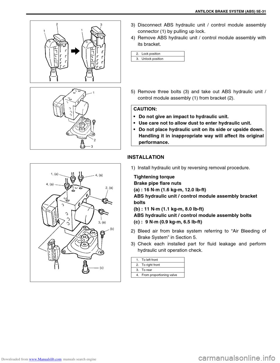
3) Disconnect ABS hydraulic unit / control module assembly
connector (1) by pulling up lock.
4) Remove ABS hydraulic unit / control module assembly with
its bracket.
5) Remove three bolts (3) and take out ABS hydraulic unit /
control module assembly (1) from bracket (2).
INSTALLATION
1) Install hydraulic unit by reversing removal procedure.
Tightening torque
Brake pipe flare nuts
(a) : 16 N·m (1.6 kg-m, 12.0 lb-ft)
ABS hydraulic unit / control module assembly bracket
bolts
(b) : 11 N·m (1.1 kg-m, 8.0 lb-ft)
ABS hydraulic unit / control module assembly bolts
(c) : 9 N·m (0.9 kg-m, 6.5 lb-ft)
2) Bleed air from brake system referring to “Air Bleeding of
Brake System” in Section 5.
3) Check each installed part for fluid leakage and perform
hydraulic unit operation check.
2. Lock position
3. Unlock position
CAUTION:
Do not give an impact to hydraulic unit.
Use care not to allow dust to enter hydraulic unit.
Do not place hydraulic unit on its side or upside down.
Handling it in inappropriate way will affect its original
performance.
1. To left front
2. To right front
3. To rear
4. From proportioning valve
Page 358 of 687

Downloaded from www.Manualslib.com manuals search engine ENGINE GENERAL INFORMATION AND DIAGNOSIS 6-1
6F2
6G
6H
6K
7A
7A1
7B1
7C1
7D
7E
7F
8B
6
8D
8E
8B
9
10A
10B
SECTION 6
ENGINE GENERAL INFORMATION AND
DIAGNOSIS
GENERAL INFORMATION AND ENGINE DIAGNOSIS ..............................................................................
6-1
ENGINE MECHANICAL ...........................................................................................................................
6A1-1
ENGINE COOLING.....................................................................................................................................
6B-1
ENGINE FUEL ............................................................................................................................................
6C-1
ENGINE AND EMISSION CONTROL SYSTEM ........................................................................................
6E-1
IGNITION SYSTEM ....................................................................................................................................
6F-1
CRANKING SYSTEM .................................................................................................................................
6G-1
CHARGING SYSTEM .................................................................................................................................
6H-1
EXHAUST SYSTEM ...................................................................................................................................
6K-1
CONTENTS
General Information .......................................... 6-3
Statement on Cleanliness and Care ............... 6-3
General Information on Engine Service .......... 6-3
Precaution on fuel system service............... 6-4
Fuel pressure relief procedure .................... 6-5
Fuel leakage check procedure .................... 6-5
Engine Diagnosis .............................................. 6-6
General Description ........................................ 6-6
On-Board Diagnostic System (Vehicle with
Immobilizer Indicator Lamp) ............................ 6-6On-Board Diagnostic System (Vehicle without
Immobilizer Indicator Lamp)............................ 6-9
Precaution in Diagnosing Trouble ................. 6-10
Engine Diagnostic Flow Table ...................... 6-11
Customer problem inspection form
(example) .................................................. 6-13
Malfunction indicator lamp (MIL) check..... 6-14
Diagnostic trouble code (DTC) check ....... 6-14
Diagnostic trouble code (DTC)
clearance................................................... 6-15 WARNING:
For vehicles equipped with Supplemental Restraint (Air Bag) System :
Service on and around the air bag system components or wiring must be performed only by an
authorized SUZUKI dealer. Refer to “Air Bag System Components and Wiring Location View” under
“General Description” in air bag system section in order to confirm whether you are performing ser-
vice on or near the air bag system components or wiring. Please observe all WARNINGS and “Ser-
vice Precautions” under “On-Vehicle Service” in air bag system section before performing service
on or around the air bag system components or wiring. Failure to follow WARNINGS could result in
unintentional activation of the system or could render the system inoperative. Either of these two
conditions may result in severe injury.
Technical service work must be started at least 90 seconds after the ignition switch is turned to the
“LOCK” position and the negative cable is disconnected from the battery. Otherwise, the system
may be activated by reserve energy in the Sensing and Diagnostic Module (SDM).
NOTE:
Whether the following systems (parts) are used in the particular vehicle or not depends on vehicle
specifications. Be sure to bear this in mind when performing service work.
EGR valve
Heated oxygen sensor(s) or CO adjusting resistor
Three-way catalytic converter (TWC) and warm up three-way catalytic converter (WU-TWC)