check oil SUZUKI JIMNY 2005 3.G Service Manual Online
[x] Cancel search | Manufacturer: SUZUKI, Model Year: 2005, Model line: JIMNY, Model: SUZUKI JIMNY 2005 3.GPages: 687, PDF Size: 13.38 MB
Page 521 of 687
Downloaded from www.Manualslib.com manuals search engine 6A1-40 ENGINE MECHANICAL (M13 ENGINE)
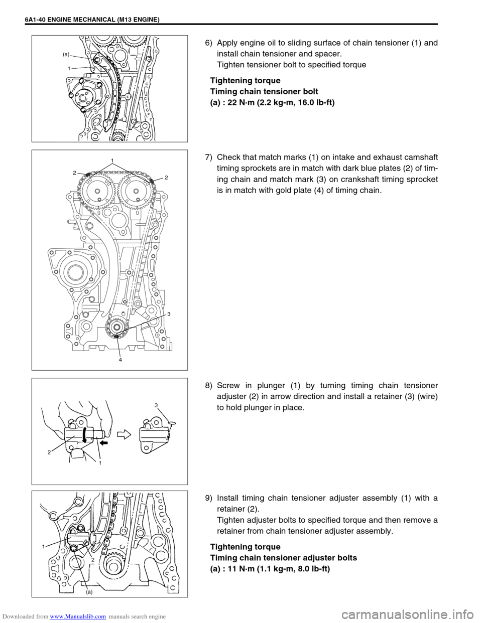
6) Apply engine oil to sliding surface of chain tensioner (1) and
install chain tensioner and spacer.
Tighten tensioner bolt to specified torque
Tightening torque
Timing chain tensioner bolt
(a) : 22 N·m (2.2 kg-m, 16.0 lb-ft)
7) Check that match marks (1) on intake and exhaust camshaft
timing sprockets are in match with dark blue plates (2) of tim-
ing chain and match mark (3) on crankshaft timing sprocket
is in match with gold plate (4) of timing chain.
8) Screw in plunger (1) by turning timing chain tensioner
adjuster (2) in arrow direction and install a retainer (3) (wire)
to hold plunger in place.
9) Install timing chain tensioner adjuster assembly (1) with a
retainer (2).
Tighten adjuster bolts to specified torque and then remove a
retainer from chain tensioner adjuster assembly.
Tightening torque
Timing chain tensioner adjuster bolts
(a) : 11 N·m (1.1 kg-m, 8.0 lb-ft)
221
3
4
Page 522 of 687
Downloaded from www.Manualslib.com manuals search engine ENGINE MECHANICAL (M13 ENGINE) 6A1-41
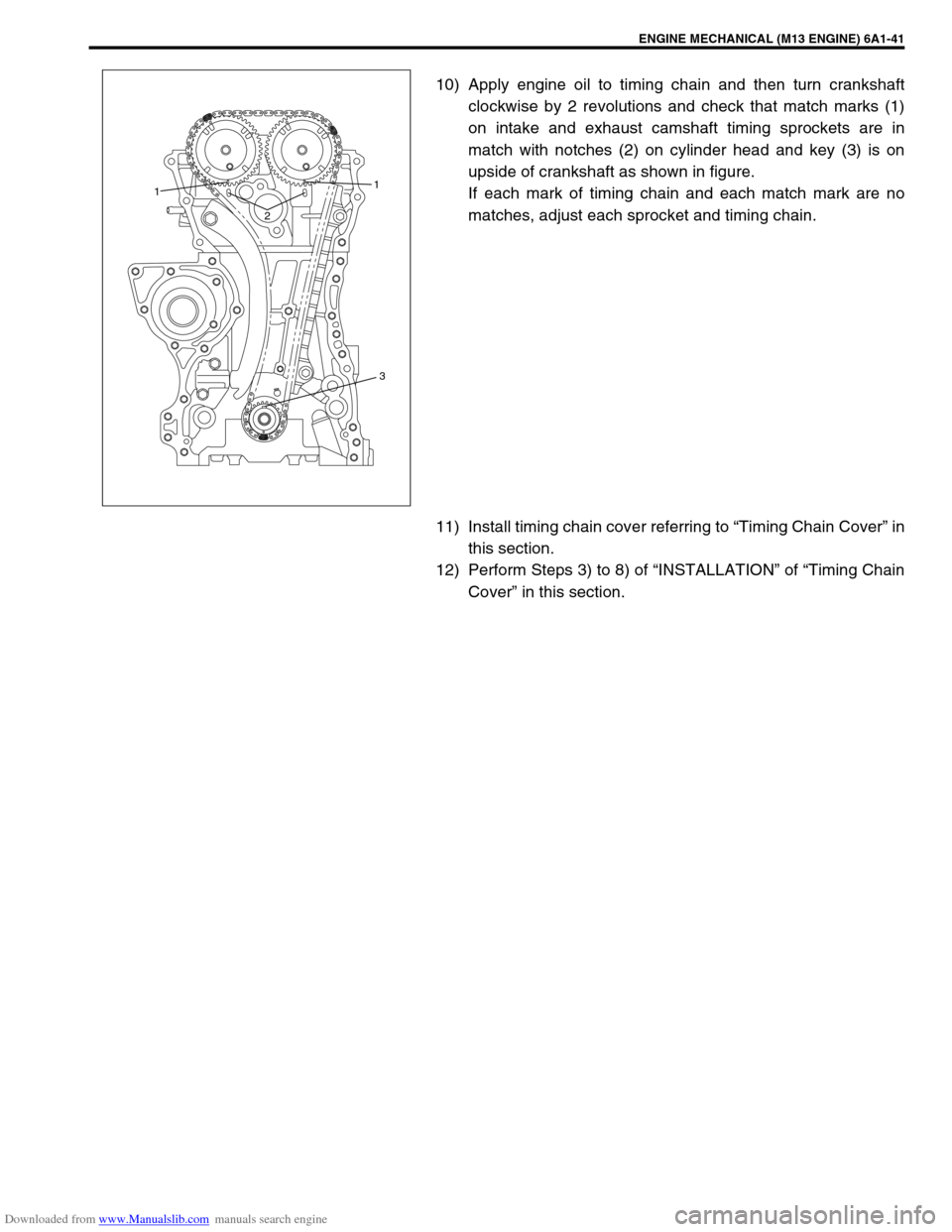
10) Apply engine oil to timing chain and then turn crankshaft
clockwise by 2 revolutions and check that match marks (1)
on intake and exhaust camshaft timing sprockets are in
match with notches (2) on cylinder head and key (3) is on
upside of crankshaft as shown in figure.
If each mark of timing chain and each match mark are no
matches, adjust each sprocket and timing chain.
11) Install timing chain cover referring to “Timing Chain Cover” in
this section.
12) Perform Steps 3) to 8) of “INSTALLATION” of “Timing Chain
Cover” in this section.
21
1
3
Page 527 of 687
Downloaded from www.Manualslib.com manuals search engine 6A1-46 ENGINE MECHANICAL (M13 ENGINE)
INSTALLATION
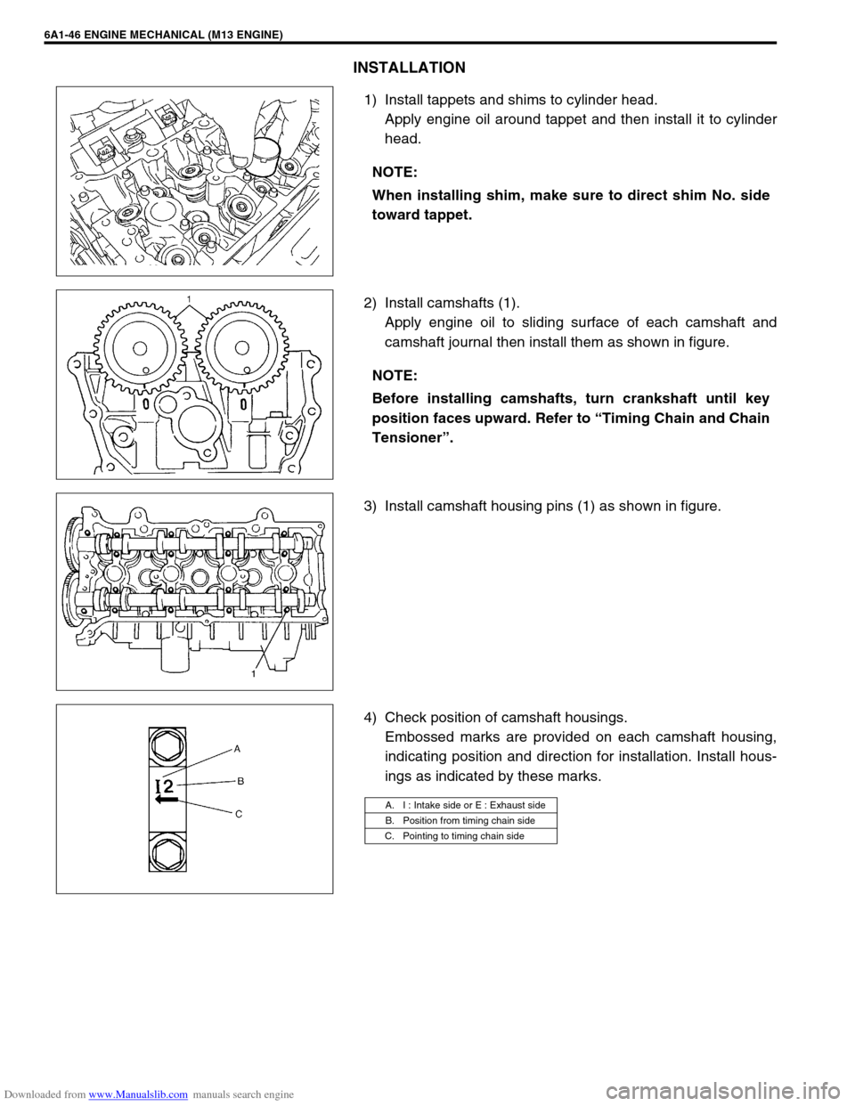
1) Install tappets and shims to cylinder head.
Apply engine oil around tappet and then install it to cylinder
head.
2) Install camshafts (1).
Apply engine oil to sliding surface of each camshaft and
camshaft journal then install them as shown in figure.
3) Install camshaft housing pins (1) as shown in figure.
4) Check position of camshaft housings.
Embossed marks are provided on each camshaft housing,
indicating position and direction for installation. Install hous-
ings as indicated by these marks. NOTE:
When installing shim, make sure to direct shim No. side
toward tappet.
NOTE:
Before installing camshafts, turn crankshaft until key
position faces upward. Refer to “Timing Chain and Chain
Tensioner”.
A. I : Intake side or E : Exhaust side
B. Position from timing chain side
C. Pointing to timing chain side
Page 528 of 687
Downloaded from www.Manualslib.com manuals search engine ENGINE MECHANICAL (M13 ENGINE) 6A1-47
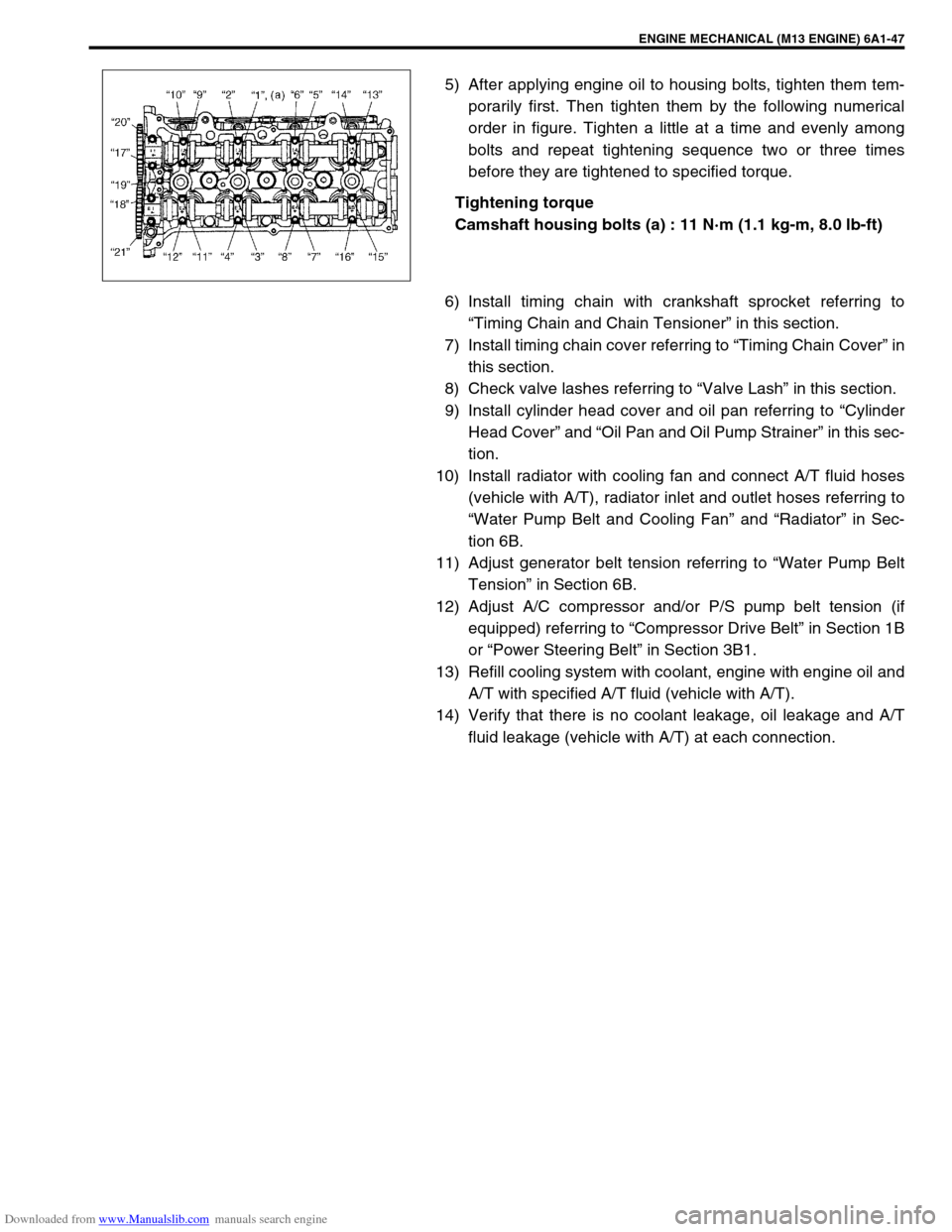
5) After applying engine oil to housing bolts, tighten them tem-
porarily first. Then tighten them by the following numerical
order in figure. Tighten a little at a time and evenly among
bolts and repeat tightening sequence two or three times
before they are tightened to specified torque.
Tightening torque
Camshaft housing bolts (a) : 11 N·m (1.1 kg-m, 8.0 lb-ft)
6) Install timing chain with crankshaft sprocket referring to
“Timing Chain and Chain Tensioner” in this section.
7) Install timing chain cover referring to “Timing Chain Cover” in
this section.
8) Check valve lashes referring to “Valve Lash” in this section.
9) Install cylinder head cover and oil pan referring to “Cylinder
Head Cover” and “Oil Pan and Oil Pump Strainer” in this sec-
tion.
10) Install radiator with cooling fan and connect A/T fluid hoses
(vehicle with A/T), radiator inlet and outlet hoses referring to
“Water Pump Belt and Cooling Fan” and “Radiator” in Sec-
tion 6B.
11) Adjust generator belt tension referring to “Water Pump Belt
Tension” in Section 6B.
12) Adjust A/C compressor and/or P/S pump belt tension (if
equipped) referring to “Compressor Drive Belt” in Section 1B
or “Power Steering Belt” in Section 3B1.
13) Refill cooling system with coolant, engine with engine oil and
A/T with specified A/T fluid (vehicle with A/T).
14) Verify that there is no coolant leakage, oil leakage and A/T
fluid leakage (vehicle with A/T) at each connection.
Page 531 of 687
Downloaded from www.Manualslib.com manuals search engine 6A1-50 ENGINE MECHANICAL (M13 ENGINE)
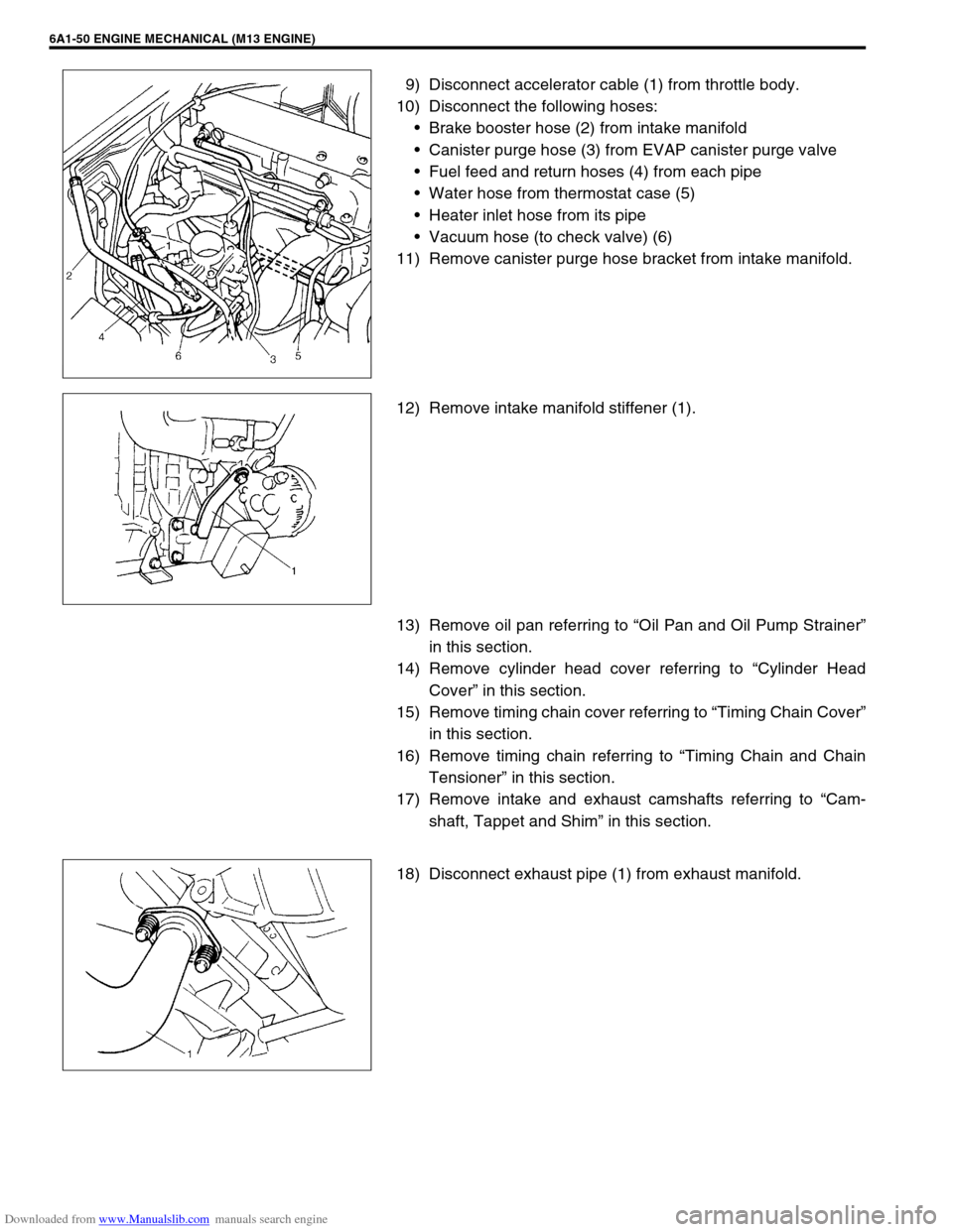
9) Disconnect accelerator cable (1) from throttle body.
10) Disconnect the following hoses:
Brake booster hose (2) from intake manifold
Canister purge hose (3) from EVAP canister purge valve
Fuel feed and return hoses (4) from each pipe
Water hose from thermostat case (5)
Heater inlet hose from its pipe
Vacuum hose (to check valve) (6)
11) Remove canister purge hose bracket from intake manifold.
12) Remove intake manifold stiffener (1).
13) Remove oil pan referring to “Oil Pan and Oil Pump Strainer”
in this section.
14) Remove cylinder head cover referring to “Cylinder Head
Cover” in this section.
15) Remove timing chain cover referring to “Timing Chain Cover”
in this section.
16) Remove timing chain referring to “Timing Chain and Chain
Tensioner” in this section.
17) Remove intake and exhaust camshafts referring to “Cam-
shaft, Tappet and Shim” in this section.
18) Disconnect exhaust pipe (1) from exhaust manifold.
Page 539 of 687

Downloaded from www.Manualslib.com manuals search engine 6A1-58 ENGINE MECHANICAL (M13 ENGINE)
2) Install valve guide to cylinder head.
Heat cylinder head uniformly to a temperature of 80 to
100 °C (176 to 212 °F) so that head will not be distorted, and
drive new valve guide into hole with special tools. Drive in
new valve guide until special tool (Valve guide installer) con-
tacts cylinder head.
After installing, make sure that valve guide protrudes by
specified dimension “a” from cylinder head.
Special tool
(A) : 09916-58210
(B) : 09916-56011
Specification for valve guide protrusion “a”
Intake and exhaust sides
: 11.3 mm (0.44 in.)
3) Ream valve guide bore with special tool (5.5 mm reamer).
After reaming, clean bore.
Special tool
(A) : 09916-34542
(B) : 09916-34550
4) Install valve spring seat to cylinder head.
5) Install new valve stem seal (1) to valve guide.
After applying engine oil to seal and spindle of special tool
(Valve guide installer handle), fit oil seal to spindle, and then
install seal to valve guide by pushing special tool by hand.
After installing, check to be sure that seal is properly fixed to
valve guide.
Special tool
(A) : 09917-98221
(B) : 09916-58210NOTE:
Do not reuse once-disassembled valve guide.
Make sure to install new valve guide.
Intake and exhaust valve guides are identical.
NOTE:
Do not reuse once-disassembled seal. Be sure to
install new seal.
When installing, do not tap or hit special tool with a
hammer or else. Install seal to guide only by pushing
special tool by hand. Tapping or hitting special tool
may cause damage to seal.
Page 541 of 687

Downloaded from www.Manualslib.com manuals search engine 6A1-60 ENGINE MECHANICAL (M13 ENGINE)
4) Make sure that oil jet (venturi plug) (1) is installed and if it is,
that it is not clogged.
When installing it, be sure to tighten to specified torque.
Tightening torque
Venturi plug (a) : 5 N·m (0.5 kg-m, 3.5 lb-ft)
5) Install cylinder head to cylinder block.
Apply engine oil to cylinder head bolts and tighten them
gradually as follows.
Cylinder head bolt diameter measurement points
“a” : 83.5 mm (2.81 in.)
“b” : 115 mm (4.53 in.)
Cylinder head bolt diameter difference (deformation)
Limit (“A” – “B”) : 0.1 mm (0.004 in.)
a) Tighten cylinder head bolts (“1” – “10”) to 20 N·m (2.0 kg-m,
14.5 lb-ft) according to numerical order as shown by using
a 12 corner socket wrenches.
b) In the same manner as in Step a), tighten them to 40 N·m
(4.0 kg-m, 29.0 lb-ft).
c) Retighten all bolts 60° according to numerical order in fig-
ure.
d) Repeat Step c).
e) Tighten bolt “A” to specified torque.
Tightening torque
Cylinder head bolt for M8 (a) : 22 N·m (2.2 kg-m, 16.0 lb-ft)
Cylinder head bolts for M10
(b) : 40 N·m (4.0 kg-m, 29.0 lb-ft) and extra tightening 60°
twice
NOTE:
If cylinder head bolts are reused, check thread diameters
of them for deformation according to the following and
replace them with new ones if thread diameter difference
exceeds limit.
Measure each thread diameter of cylinder head bolt (1) at
“A” on 83.5 mm (2.81 in.) from seat side of flange bolt
and “B” on 115 mm (4.53 in.) from seat side of flange bolt
by using a micrometer (2).
Then calculate difference in diameters (“A” – “B”).
If it exceeds limit, replace with new one.
“A”
“a”
“b”“B”
1
12
NOTE:
Be sure to tighten M8 bolt (“A”) after securing the other
bolt.
Page 542 of 687

Downloaded from www.Manualslib.com manuals search engine ENGINE MECHANICAL (M13 ENGINE) 6A1-61
6) Install exhaust manifold stiffener and exhaust pipe referring
to “Exhaust Manifold” in this section.
7) Install camshafts, timing chain and chain cover referring to
“Camshaft, Tappet and Shim”, “Timing Chain and Chain
Tensioner” and “Timing Chain Cover” in this section.
8) Install cylinder head cover and oil pan referring to “Cylinder
Head Cover” and “Oil Pan and Oil Pump Strainer” in this sec-
tion.
9) Install intake manifold stiffener and connect each hoses and
electric lead wires securely.
10) Install air cleaner outlet hoses.
11) Install radiator with cooling fan and connect A/T fluid hoses
(vehicle with A/T), radiator inlet and outlet hoses referring to
“Water Pump Belt and Cooling Fan” and “Radiator” in Sec-
tion 6B.
12) Adjust generator belt tension referring to “Water Pump Belt
Tension” in Section 6B.
13) Adjust A/C compressor and/or P/S pump belt tension (if
equipped) referring to “Compressor Drive Belt” in Section 1B
or “Power Steering Belt” in Section 3B1.
14) Adjust accelerator cable play referring to “Accelerator Cable
Adjustment” in Section 6E.
15) Check to ensure that all removed parts are back in place.
Reinstall any necessary parts which have not been rein-
stalled.
16) Refill cooling system with coolant, engine with engine oil and
A/T with specified A/T fluid (vehicle with A/T).
17) Connect negative cable at battery.
18) Verify that there is no fuel leakage, coolant leakage, oil leak-
age, A/T fluid leakage (vehicle with A/T) and exhaust gas
leakage at each connection.
Page 546 of 687
Downloaded from www.Manualslib.com manuals search engine ENGINE MECHANICAL (M13 ENGINE) 6A1-65
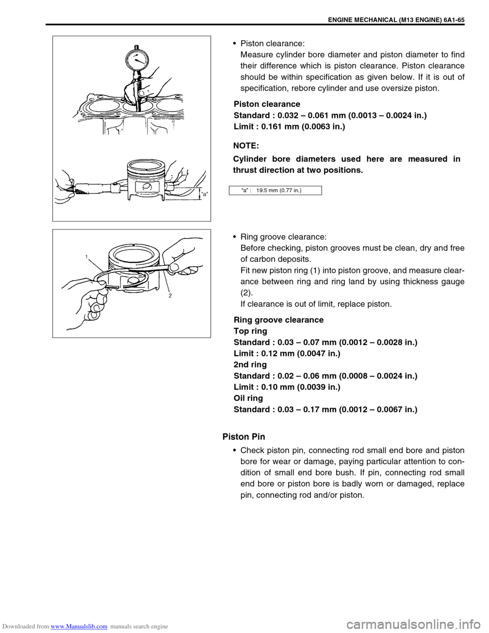
Piston clearance:
Measure cylinder bore diameter and piston diameter to find
their difference which is piston clearance. Piston clearance
should be within specification as given below. If it is out of
specification, rebore cylinder and use oversize piston.
Piston clearance
Standard : 0.032 – 0.061 mm (0.0013 – 0.0024 in.)
Limit : 0.161 mm (0.0063 in.)
Ring groove clearance:
Before checking, piston grooves must be clean, dry and free
of carbon deposits.
Fit new piston ring (1) into piston groove, and measure clear-
ance between ring and ring land by using thickness gauge
(2).
If clearance is out of limit, replace piston.
Ring groove clearance
Top ring
Standard : 0.03 – 0.07 mm (0.0012 – 0.0028 in.)
Limit : 0.12 mm (0.0047 in.)
2nd ring
Standard : 0.02 – 0.06 mm (0.0008 – 0.0024 in.)
Limit : 0.10 mm (0.0039 in.)
Oil ring
Standard : 0.03 – 0.17 mm (0.0012 – 0.0067 in.)
Piston Pin
Check piston pin, connecting rod small end bore and piston
bore for wear or damage, paying particular attention to con-
dition of small end bore bush. If pin, connecting rod small
end bore or piston bore is badly worn or damaged, replace
pin, connecting rod and/or piston. NOTE:
Cylinder bore diameters used here are measured in
thrust direction at two positions.
“a” : 19.5 mm (0.77 in.)
Page 547 of 687
Downloaded from www.Manualslib.com manuals search engine 6A1-66 ENGINE MECHANICAL (M13 ENGINE)
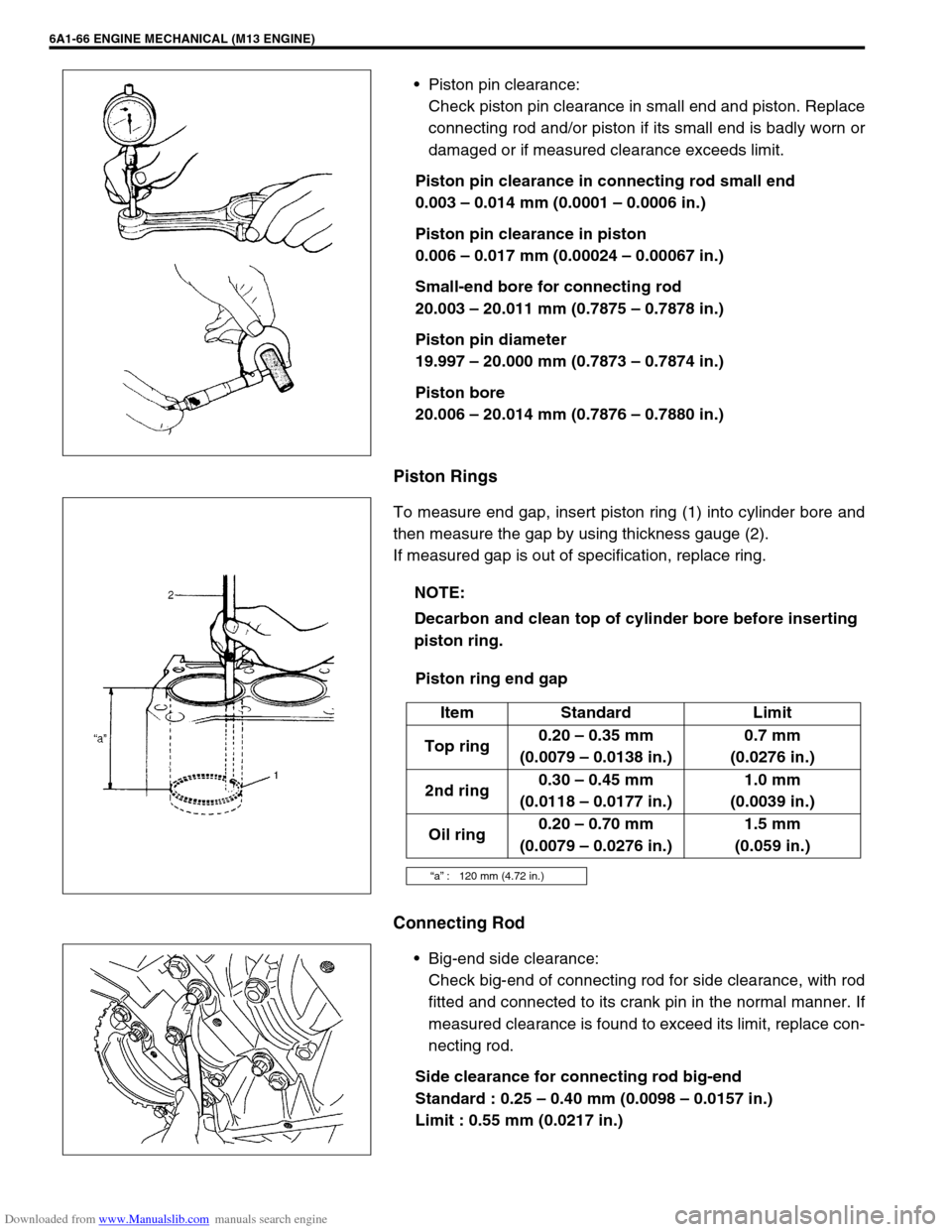
Piston pin clearance:
Check piston pin clearance in small end and piston. Replace
connecting rod and/or piston if its small end is badly worn or
damaged or if measured clearance exceeds limit.
Piston pin clearance in connecting rod small end
0.003 – 0.014 mm (0.0001 – 0.0006 in.)
Piston pin clearance in piston
0.006 – 0.017 mm (0.00024 – 0.00067 in.)
Small-end bore for connecting rod
20.003 – 20.011 mm (0.7875 – 0.7878 in.)
Piston pin diameter
19.997 – 20.000 mm (0.7873 – 0.7874 in.)
Piston bore
20.006 – 20.014 mm (0.7876 – 0.7880 in.)
Piston Rings
To measure end gap, insert piston ring (1) into cylinder bore and
then measure the gap by using thickness gauge (2).
If measured gap is out of specification, replace ring.
Piston ring end gap
Connecting Rod
Big-end side clearance:
Check big-end of connecting rod for side clearance, with rod
fitted and connected to its crank pin in the normal manner. If
measured clearance is found to exceed its limit, replace con-
necting rod.
Side clearance for connecting rod big-end
Standard : 0.25 – 0.40 mm (0.0098 – 0.0157 in.)
Limit : 0.55 mm (0.0217 in.)
NOTE:
Decarbon and clean top of cylinder bore before inserting
piston ring.
Item Standard Limit
Top ring0.20 – 0.35 mm
(0.0079 – 0.0138 in.)0.7 mm
(0.0276 in.)
2nd ring0.30 – 0.45 mm
(0.0118 – 0.0177 in.)1.0 mm
(0.0039 in.)
Oil ring0.20 – 0.70 mm
(0.0079 – 0.0276 in.)1.5 mm
(0.059 in.)
“a” : 120 mm (4.72 in.)