PCV SUZUKI JIMNY 2005 3.G Service Workshop Manual
[x] Cancel search | Manufacturer: SUZUKI, Model Year: 2005, Model line: JIMNY, Model: SUZUKI JIMNY 2005 3.GPages: 687, PDF Size: 13.38 MB
Page 27 of 687

Downloaded from www.Manualslib.com manuals search engine 0A-22 GENERAL INFORMATION
LLH
LSPVLeft Hand
Load Sensing Proportioning Valve
TTBI
TCC
TCM
TP Sensor
TVV
TWC
2WDThrottle Body Fuel Injection
(Single-Point Fuel Injection, SPI)
Torque Converter Clutch
Transmission Control Module
(A/T Controller, A/T Control Mod-
ule)
Throttle Position Sensor
Thermal Vacuum Valve
(Thermal Vacuum Switching Valve,
TVSV, Bimetal Vacuum Switching
Valve, BVSV)
Three Way Catalytic Converter
(Three Way Catalyst)
2 Wheel Drive MMAF Sensor
MAP Sensor
Max
MFI
Min
MIL
M/TMass Air Flow Sensor
(Air Flow Sensor, AFS, Air Flow
Meter, AFM)
Manifold Absolute Pressure
Sensor (Pressure Sensor, PS)
Maximum
Multiport Fuel Injection
(Multipoint Fuel Injection)
Minimum
Malfunction Indicator Lamp
(“CHECK ENGINE” Light)
Manual Transmission
N NOx Nitrogen Oxides VVIN
VSSVehicle Identification Number
Vehicle Speed Sensor
OOBD
O/D
OHCOn-Board Diagnostic System
(Self-Diagnosis Function)
Overdrive
Over Head CamshaftWWU-OC
WU-TWCWarm Up Oxidation Catalytic
Converter
Warm Up Three Way Catalytic
Converter
PPNP
P/S
PSP Switch
PCM
PCVPark/Neutral Position
Power Steering
Power Steering Pressure Switch
(P/S Pressure Switch)
Powertrain Control Module
Positive Crankcase Ventilation
R RH Right Hand
SSAE
SDM
SFI
SOHCSociety of Automotive Engineers
Sensing and Diagnostic Module
(Air bag controller, Air bag control
module)
Sequential Multiport Fuel Injection
Single Over Head Camshaft
Page 32 of 687

Downloaded from www.Manualslib.com manuals search engine MAINTENANCE AND LUBRICATION 0B-1
0A 6F1
0B
0B
6G
1A 6H
1B 6K
37A
3A 7A1
3B1 7B1
3C1 7C1
3D 7D
3E 7E
3F 7F
4A2 8A
4B 8B
8C
58D
5A 8E
5B
5C 9
5E
5E1 10
10A
610B
6-1
6A1
6A2
6A4
6B
6C
6E1
6E2
SECTION 0B
MAINTENANCE AND LUBRICATION
CONTENTS
Maintenance Schedule .................................. 0B-2
Maintenance Schedule Under Normal
Driving Conditions ........................................ 0B-2
Maintenance Recommended Under Severe
Driving Conditions ........................................ 0B-4
Maintenance Service...................................... 0B-5
Engine .......................................................... 0B-5
Drive Belt .................................................. 0B-5
Valve Lash................................................ 0B-6
Engine Oil and Filter ................................. 0B-6
Engine Coolant ......................................... 0B-8
Exhaust System ....................................... 0B-8
Ignition System ............................................. 0B-9
Spark Plugs .............................................. 0B-9
Fuel System ................................................. 0B-9
Air Cleaner Filter ...................................... 0B-9
Fuel Lines and Connections ................... 0B-10
Fuel Filter ............................................... 0B-10
Fuel Tank ............................................... 0B-10
Emission Control System ........................... 0B-10
Crankcase Ventilation Hoses and
Connections ........................................... 0B-10
PCV (Positive Crankcase Ventilation)
Valve ..................................................... 0B-11Fuel Evaporative Emission Control
System ................................................... 0B-11
Chassis and Body ...................................... 0B-11
Clutch ..................................................... 0B-11
Brake Discs and Pads ............................ 0B-11
Brake Drums and Shoes ........................ 0B-12
Brake Hoses and Pipes.......................... 0B-12
Brake Fluid ............................................. 0B-12
Parking Brake Lever and Cable ............. 0B-13
Tires/Wheels .......................................... 0B-13
Suspension System ............................... 0B-14
Propeller Shafts...................................... 0B-15
Manual Transmission Oil........................ 0B-16
Automatic Transmission Fluid ................ 0B-16
Transfer and Differential Oil ................... 0B-17
Steering System ..................................... 0B-18
Steering Knuckle Seal ............................ 0B-18
Power Steering (P/S) System
(if equipped) ........................................... 0B-19
All Hinges, Latches and Locks ............... 0B-19
Final Inspection............................................ 0B-20
Recommended Fluids and Lubricants ....... 0B-22
WARNING:
For vehicles equipped with Supplemental Restraint (Air Bag) System:
Service on and around the air bag system components or wiring must be performed only by an
authorized SUZUKI dealer. Refer to “Air Bag System Components and Wiring Location View” under
“General Description” in air bag system section in order to confirm whether you are performing ser-
vice on or near the air bag system components or wiring. Please observe all WARNINGS and “Ser-
vice Precautions” under “On-Vehicle Service” in air bag system section before performing service
on or around the air bag system components or wiring. Failure to follow WARNINGS could result in
unintentional activation of the system or could render the system inoperative. Either of these two
conditions may result in severe injury.
Technical service work must be started at least 90 seconds after the ignition switch is turned to the
“LOCK” position and the negative cable is disconnected from the battery. Otherwise, the system
may be activated by reserve energy in the Sensing and Diagnostic Module (SDM).
Page 33 of 687

Downloaded from www.Manualslib.com manuals search engine 0B-2 MAINTENANCE AND LUBRICATION
Maintenance Schedule
Maintenance Schedule Under Normal Driving Conditions
NOTE:
This interval should be judged by odometer reading or months, whichever comes first.
This table includes service as scheduled up to 90,000 km (54,000 miles) mileage. Beyond 90,000 km
(54,000 miles), carry out the same services at the same intervals respectively.
IntervalKm (x 1,000) 15 30 45 60 75 90
Miles (x 1,000) 9 1827364554
Months 12 24 36 48 60 72
ENGINE
Drive belt V-belt I R I R I R
V-rib belt (Flat type)––I––R
Valve lash (clearance) –I–I–I
Engine oil and oil filter R R R R R R
Engine coolant––R––R
Exhaust system–I–I–I
IGNITION SYSTEM
✱Spark plugs When
unleaded
fuel is usedVehicle without
HO2SNickel spark
plug–R–R–R
Iridium spark
plug––R––R
Vehicle with
HO2SNickel spark
plug––R––R
Iridium spark
plug–––R––
When leaded fuel is used, refer to “Maintenance Recommended Under Severe Driving Condi-
tions” in this section.
FUEL SYSTEM
Air cleaner filter I I R I I R
Fuel lines and connections–I–I–I
Fuel filter Replace every 210,000 km (126,000 miles).
Fuel tank––I––I
EMISSION CONTROL SYSTEM
Crankcase ventilation hoses and connections
(Vehicle without HO2S)––I––I
✱PCV valve Vehicle without HO2S––I––I
Vehicle with HO2S–––––I
✱Fuel evaporative emission
control systemVehicle without HO2S–I–I–I
Vehicle with HO2S–––––I
NOTE:
“R”: Replace or change
“I”: Inspect and correct, replace or lubricate if necessary
For Sweden, items with
✱
✱✱ ✱ (asterisk) should be performed by odometer reading only.
For spark plugs, replace every 50,000 km if the local law requires.
Nickel spark plug: BKR6E-11 (NGK) or K20PR-U11 (DENSO)
Iridium spark plug: IFR5E11 (NGK) or SK16PR-A11 (DENSO)
Page 41 of 687

Downloaded from www.Manualslib.com manuals search engine 0B-10 MAINTENANCE AND LUBRICATION
REPLACEMENT
Replace air cleaner filter with new one according to steps 1), 2)
and 5), 6) of inspection procedure.
Fuel Lines and Connections
INSPECTION
1) Visually inspect fuel lines and connections for evidence of
fuel leakage, hose cracking and damage. Make sure all
clamps are secure.
Repair leaky joints, if any.
Replace hoses that are suspected of being cracked.
Fuel Filter
REPLACEMENT
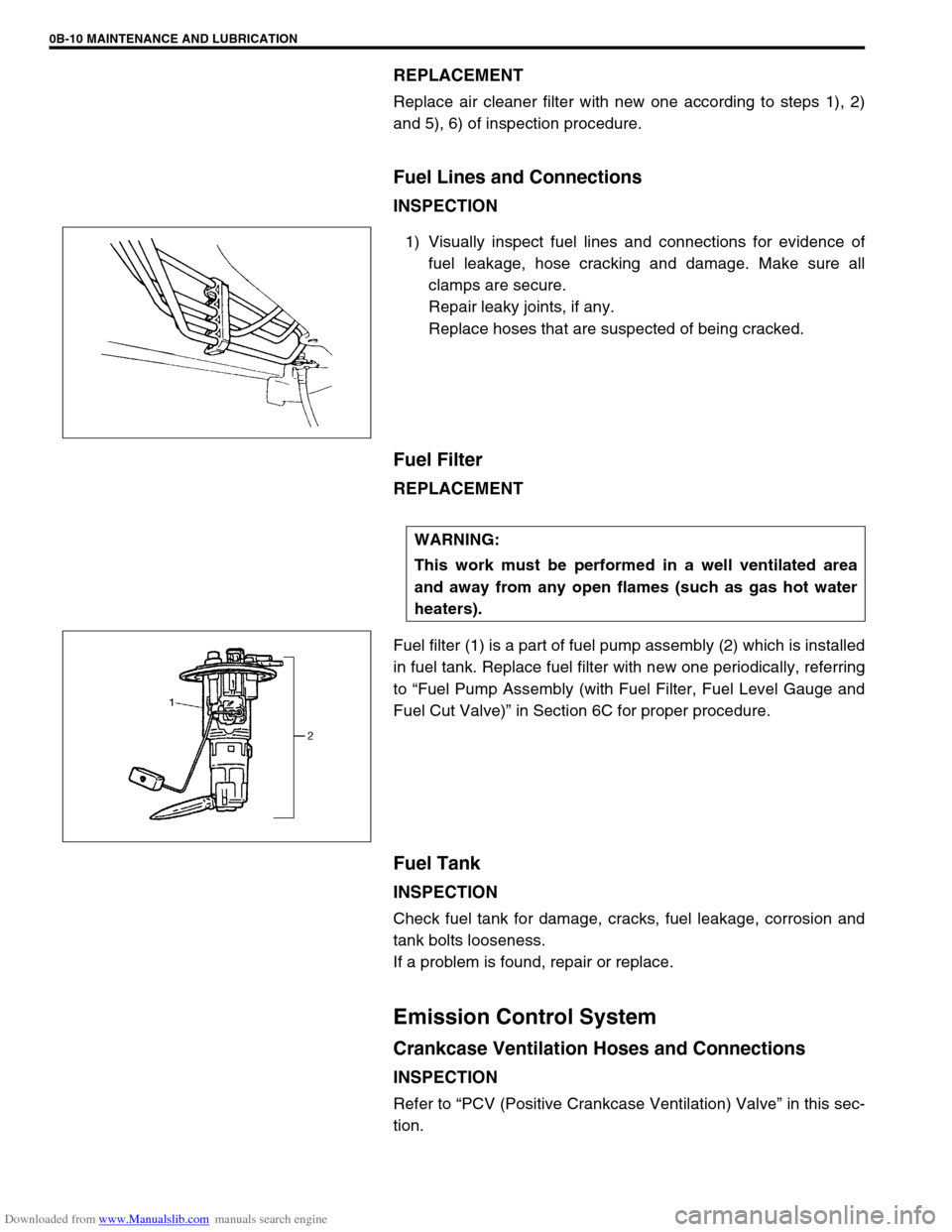
Fuel filter (1) is a part of fuel pump assembly (2) which is installed
in fuel tank. Replace fuel filter with new one periodically, referring
to “Fuel Pump Assembly (with Fuel Filter, Fuel Level Gauge and
Fuel Cut Valve)” in Section 6C for proper procedure.
Fuel Tank
INSPECTION
Check fuel tank for damage, cracks, fuel leakage, corrosion and
tank bolts looseness.
If a problem is found, repair or replace.
Emission Control System
Crankcase Ventilation Hoses and Connections
INSPECTION
Refer to “PCV (Positive Crankcase Ventilation) Valve” in this sec-
tion.
WARNING:
This work must be performed in a well ventilated area
and away from any open flames (such as gas hot water
heaters).
Page 42 of 687

Downloaded from www.Manualslib.com manuals search engine MAINTENANCE AND LUBRICATION 0B-11
PCV (Positive Crankcase Ventilation) Valve
INSPECTION
Check crankcase ventilation hose and PCV hose for leaks, cracks
or clog, and PCV valve for stick or clog. Refer to “PCV System” of
Section 6E for PCV valve checking procedure.
Fuel Evaporative Emission Control System
INSPECTION
1) Visually inspect hoses for cracks, damage, or excessive
bends. Inspect all clamps for damage and proper position.
2) Check EVAP canister for operation and clog, referring to
“Evaporative Emission (EVAP) Control System” in Section
6E.
If a malfunction is found, repair or replace.
Chassis and Body
Clutch
INSPECTION
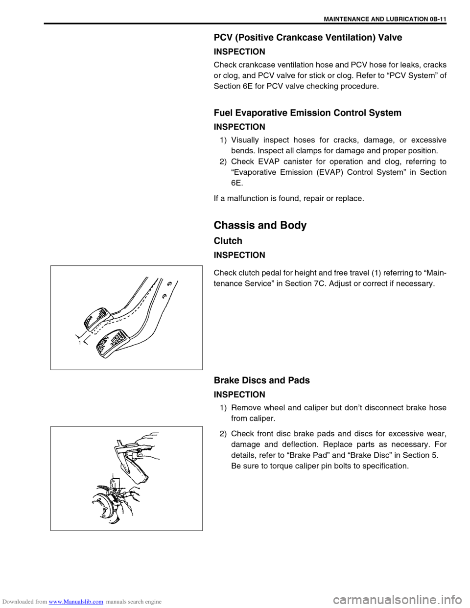
Check clutch pedal for height and free travel (1) referring to “Main-
tenance Service” in Section 7C. Adjust or correct if necessary.
Brake Discs and Pads
INSPECTION
1) Remove wheel and caliper but don’t disconnect brake hose
from caliper.
2) Check front disc brake pads and discs for excessive wear,
damage and deflection. Replace parts as necessary. For
details, refer to “Brake Pad” and “Brake Disc” in Section 5.
Be sure to torque caliper pin bolts to specification.
Page 380 of 687
![SUZUKI JIMNY 2005 3.G Service Workshop Manual Downloaded from www.Manualslib.com manuals search engine ENGINE GENERAL INFORMATION AND DIAGNOSIS 6-23
[D] Fig. 4 for Step 7 or 8 / [E] Fig. 5 for Step 10 / [F] Fig. 6 for Step 13
Engine diagnosis tab SUZUKI JIMNY 2005 3.G Service Workshop Manual Downloaded from www.Manualslib.com manuals search engine ENGINE GENERAL INFORMATION AND DIAGNOSIS 6-23
[D] Fig. 4 for Step 7 or 8 / [E] Fig. 5 for Step 10 / [F] Fig. 6 for Step 13
Engine diagnosis tab](/img/20/7588/w960_7588-379.png)
Downloaded from www.Manualslib.com manuals search engine ENGINE GENERAL INFORMATION AND DIAGNOSIS 6-23
[D] Fig. 4 for Step 7 or 8 / [E] Fig. 5 for Step 10 / [F] Fig. 6 for Step 13
Engine diagnosis table
Perform troubleshooting referring to following table when ECM has no DTC and no abnormality found in visual
inspection and engine basic inspection previously.
Condition Possible Cause Reference Item
Hard Starting
(Engine cranks OK)Faulty ignition coil Ignition coil assembly in Section 6F.
Faulty CMP sensing rotor or CKP sensing
rotorCMP sensing rotor or CKP sensing
rotor inspection in Section 6E.
Faulty idle air control system Diagnostic Flow Table B-4
Faulty ECT sensor, TP sensor, CKP sen-
sor, CMP sensor or MAP sensorECT sensor, TP sensor, CKP sensor,
CMP sensor or MAP sensor in Sec-
tion 6E.
Fuel pressure out of specification Diagnostic Flow Table B-3
Faulty fuel injector Diagnostic Flow Table B-1
Faulty ECM Inspection of ECM and its circuit in
this section.
Malfunctioning PCV system PCV system in Section 6E.
Low compression Compression check in Section 6A1.
Improper valve lash Valve lash in Section 6A1.
Improper valve timing Timing chain and chain tensioner in
Section 6A1.
Compression leak from valve seat Valves and cylinder head in Section
6A1.
Sticky valve stem Valves and cylinder head in Section
6A1.
Weak or damaged valve springs Valves and cylinder head in Section
6A1.
Compression leak at cylinder head gasket Valves and cylinder head in Section
6A1.
Sticking or damaged piston ring Pistons, piston rings, connecting rods
and cylinders in Section 6A1.
Worn piston, ring or cylinder Pistons, piston rings, connecting rods
and cylinders in Section 6A1.
Page 381 of 687

Downloaded from www.Manualslib.com manuals search engine 6-24 ENGINE GENERAL INFORMATION AND DIAGNOSIS
Engine has no power
Engine overheating Refer to “Overheating” of this table.
Faulty ignition coil Ignition coil assembly in Section 6F.
Faulty knock sensor Knock sensor malfunction in this sec-
tion.
Fuel pressure out of specification Diagnostic Flow Table B-3
Faulty injector Diagnostic Flow Table B-1
Faulty TP sensor, ECT sensor or MAP
sensorTP sensor, ECT sensor or MAP sen-
sor in Section 6E.
Faulty ECM Inspection of ECM and its circuit in
this section.
Malfunctioning EGR valve (if equipped) EGR system in Section 6E.
Maladjusted accelerator cable play Accelerator cable adjustment in Sec-
tion 6E.
Low compression Previously outlined.
Dragging brakes Diagnosis table in Section 5.
Slipping clutch Diagnosis table in Section 7C.
Improper engine idling
or engine fails to idleFaulty ignition coil Ignition coil assembly in Section 6F.
Engine overheating Refer to “Overheating” of this table.
Fuel pressure out of specification Diagnostic Flow Table B-3
Faulty idle air control system Diagnostic Flow Table B-4
Faulty evaporative emission control sys-
temEVAP control system in Section 6E.
Faulty injector Diagnostic Flow Table B-1
Faulty ECT sensor, TP sensor or MAP
sensorECT sensor, TP sensor or MAP sen-
sor in Section 6E.
Malfunctioning PCV system PCV system in Section 6F.
Faulty ECM Inspection of ECM and its circuit in
this section.
Faulty EGR system (if equipped) EGR system in Section 6E.
Low compression Previously outlined.
Engine hesitates
(Momentary lack of
response as the accel-
erator is depressed.
Can occur at all vehicle
speeds.
Usually most severe
when first trying to
make the vehicle move,
as from a stop sign.)Faulty ignition coil Ignition coil assembly in Section 6F.
Engine overheating Refer to “Overheating” of this table.
Fuel pressure out of specification Diagnostic Flow Table B-3
Faulty injector Diagnostic Flow Table B-1
Faulty TP sensor, ECT sensor or MAP
sensorTP sensor, ECT sensor or MAP sen-
sor in Section 6E.
Faulty ECM Inspection of ECM and its circuit in
this section.
Malfunctioning EGR valve (if equipped) EGR system in Section 6E.
Low compression Previously outlined.
Surges
(Engine power variation
under steady throttle or
cruise.
Feels like the vehicle
speeds up and down
with no change in the
accelerator pedal.)Faulty ignition coil or high-tension cord Ignition coil assembly or high-tension
cords in Section 6F.
Variable fuel pressure Diagnostic Flow Table B-3
Faulty MAP sensor MAP sensor in Section 6E.
Faulty injector Diagnostic Flow Table B-1
Faulty ECM Inspection of ECM and its circuit in
this section.
Malfunctioning EGR valve (if equipped) EGR system in Section 6E. Condition Possible Cause Reference Item
Page 384 of 687

Downloaded from www.Manualslib.com manuals search engine ENGINE GENERAL INFORMATION AND DIAGNOSIS 6-27
Condition Possible Cause Reference Item
Excessive hydrocar-
bon (HC) emission or
Excessive carbon mon-
oxide (CO) emissionFaulty ignition coil Ignition coil assembly in Section 6F.
Fuel pressure out of specification Diagnostic Flow Table B-3
Lead contamination of three way catalytic
converterMaintenance in Section 6K.
Malfunctioning PCV system PCV system in Section 6E.
Faulty EVAP control system EVAP control system in Section 6E.
Closed loop system (A/F feed back com-
pensation) fails
–Faulty TP sensor
–Faulty ECT sensor or MAP sensor
–Faulty oxygen sensorCheck oxygen sensor output voltage.
Refer to DTC P0130 (No.14) Table in
this section.
Faulty injector Diagnostic Flow Table B-1
Faulty ECM Inspection of ECM and its circuit in
this section.
Low compression Previously outlined.
Excessive nitrogen
oxides (NOx) emissionFuel pressure out of specification Diagnostic Flow Table B-3
Lead contamination of three way catalytic
converterMaintenance in Section 6K.
Closed loop system (A/F feed back com-
pensation) fails
–Faulty TP sensor
–Faulty ECT sensor or MAP sensor
–Faulty oxygen sensorCheck oxygen sensor output voltage
Refer to DTC P0130 (No.14) Table in
this section.
Faulty injector Diagnostic Flow Table B-1
Faulty ECM Inspection of ECM and its circuit in
this section.
Faulty EGR system (if equipped) EGR system in Section 6E.
Page 425 of 687
![SUZUKI JIMNY 2005 3.G Service Workshop Manual Downloaded from www.Manualslib.com manuals search engine 6-68 ENGINE GENERAL INFORMATION AND DIAGNOSIS
DTC P0171 Fuel System Too Lean
DTC P0172 Fuel System Too Rich
CIRCUIT DESCRIPTION
[a] : Signal to SUZUKI JIMNY 2005 3.G Service Workshop Manual Downloaded from www.Manualslib.com manuals search engine 6-68 ENGINE GENERAL INFORMATION AND DIAGNOSIS
DTC P0171 Fuel System Too Lean
DTC P0172 Fuel System Too Rich
CIRCUIT DESCRIPTION
[a] : Signal to](/img/20/7588/w960_7588-424.png)
Downloaded from www.Manualslib.com manuals search engine 6-68 ENGINE GENERAL INFORMATION AND DIAGNOSIS
DTC P0171 Fuel System Too Lean
DTC P0172 Fuel System Too Rich
CIRCUIT DESCRIPTION
[a] : Signal to decrease amount of fuel injection [d] : A/F mixture becomes richer
(Oxygen concentration decreases)1. Injector
[b] : Signal to increase amount of fuel injection [e] : High voltage 2. Heated oxygen sensor-1 (HO2S-1)
[c] : A/F mixture becomes leaner
(Oxygen concentration increases)[f] : Low voltage
DTC DETECTING CONDITION POSSIBLE CAUSE
When following condition occurs while engine running
under closed loop condition.
–Air / fuel ratio too lean
(Total fuel trim (short and long terms added) is more
than 30%)
or
–Air / fuel ratio too rich
(Total fuel trim is less than –30%)
✱
✱✱ ✱2 driving cycle detection logic, continuous monitoring.Vacuum leaks (air drawn in).
Exhaust gas leakage.
Heated oxygen sensor-1 circuit malfunction.
Fuel pressure out of specification.
Fuel injector malfunction (clogged or leakage).
MAP sensor poor performance.
ECT sensor poor performance.
IAT sensor poor performance.
TP sensor poor performance.
EVAP control system malfunction.
PCV valve malfunction.
Page 427 of 687

Downloaded from www.Manualslib.com manuals search engine 6-70 ENGINE GENERAL INFORMATION AND DIAGNOSIS
5 Check Fuel Injectors and Circuit.
1) Using sound scope (4) or such, check operating
sound of each injector (5) when engine is run-
ning. Cycle of operating sound should vary
according to engine speed. See Fig. 3.
If no sound or an unusual sound is heard, check
injector circuit (wire or coupler) or injector.
2) Turn ignition switch OFF and disconnect a fuel
injector connector.
3) Check for proper connection to fuel injector at
each terminal.
4) If OK, then check injector resistance.
See Fig. 4.
Injector resistance
11.3 – 13.8 ohm at 20 °C (68 °F)
5) Carry out steps 1) and 3) on each injector.
6) Check each injector for injected fuel volume
referring to Section 6E. See Fig. 5.
Injected fuel volume
43 – 47 cc/15 sec (1.45/1.51 – 1.58/1.65 US/
Imp.oz/15 sec)
7) Check each injector for fuel leakage after injec-
tor closed.
Fuel leakage
Less than 1 drop / min. (1)
Is check result in step 1) and 3) to 7) satisfactory?Go to Step 6. Check injector circuit or
replace fuel injector(s).
6 Check EVAP Canister Purge Valve.
1) Disconnect purge hose (2) from EVAP canister.
2) Place finger against the end of disconnected
hose.
3) Check that vacuum is not felt there when
engine is cool and running at idle. See Fig. 6.
Is vacuum felt?Check EVAP control
system (See Section
6E).Go to Step 7.
7 Check intake manifold absolute pressure sensor for
performance (See step 4) of DTC P0105 (No.11)
Diag. Flow Table).
Is it in good condition?Go to Step 8. Repair or replace.
8 Check engine coolant temp. sensor for perfor-
mance (See Section 6E).
Is it in good condition?Go to Step 9. Replace engine coolant
temp. sensor.
9 Check intake air temp. sensor for performance
(See Section 6E).
Is it in good condition?Go to Step 10. Replace intake air temp.
sensor.
10 Check throttle position sensor for performance
(See step 5) of DTC P0121 Diag. Flow Table).
Is it in good condition?Go to Step 11. Replace throttle position
sensor.
11 Check PCV valve for valve clogging
(See Section 6E).
Is it good condition?Substitute a known-
good ECM and recheck.Replace PCV valve. Step Action Yes No