Shim SUZUKI JIMNY 2005 3.G Service Workshop Manual
[x] Cancel search | Manufacturer: SUZUKI, Model Year: 2005, Model line: JIMNY, Model: SUZUKI JIMNY 2005 3.GPages: 687, PDF Size: 13.38 MB
Page 102 of 687
Downloaded from www.Manualslib.com manuals search engine AIR CONDITIONING (OPTIONAL) 1B-41
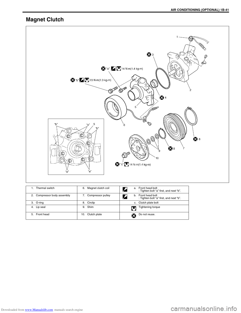
Magnet Clutch
1. Thermal switch 6. Magnet clutch coil a. Front head bolt
: Tighten bolt “a” first, and next “b”.
2. Compressor body assembly 7. Compressor pulley b. Front head bolt
: Tighten bolt “a” first, and next “b”.
3. O-ring 8. Circlip c. Clutch plate bolt
4. Lip seal 9. Shim Tightening torque
5. Front head 10. Clutch plate Do not reuse.
Page 105 of 687
Downloaded from www.Manualslib.com manuals search engine 1B-44 AIR CONDITIONING (OPTIONAL)
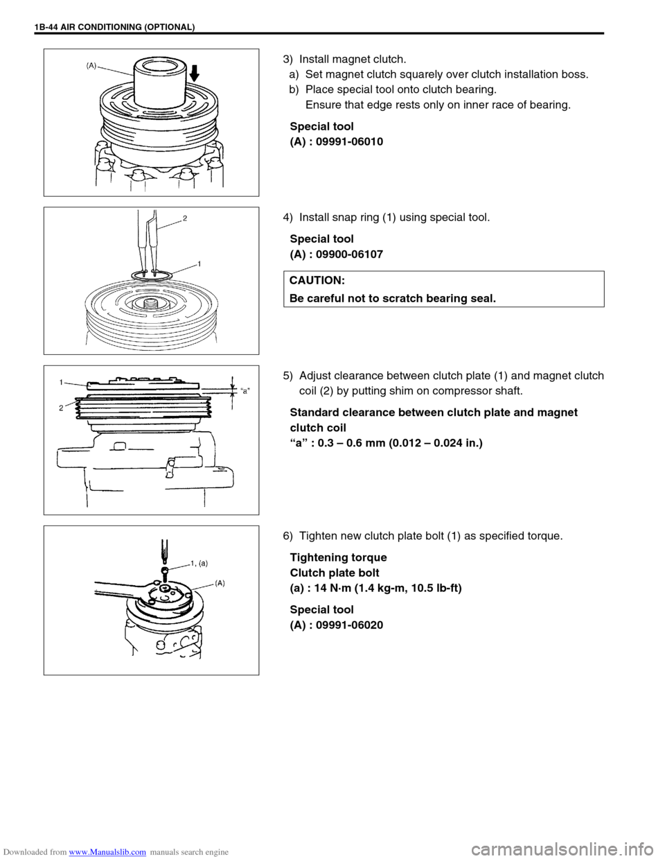
3) Install magnet clutch.
a) Set magnet clutch squarely over clutch installation boss.
b) Place special tool onto clutch bearing.
Ensure that edge rests only on inner race of bearing.
Special tool
(A) : 09991-06010
4) Install snap ring (1) using special tool.
Special tool
(A) : 09900-06107
5) Adjust clearance between clutch plate (1) and magnet clutch
coil (2) by putting shim on compressor shaft.
Standard clearance between clutch plate and magnet
clutch coil
“a” : 0.3 – 0.6 mm (0.012 – 0.024 in.)
6) Tighten new clutch plate bolt (1) as specified torque.
Tightening torque
Clutch plate bolt
(a) : 14 N·m (1.4 kg-m, 10.5 lb-ft)
Special tool
(A) : 09991-06020
CAUTION:
Be careful not to scratch bearing seal.
Page 112 of 687

Downloaded from www.Manualslib.com manuals search engine STEERING, SUSPENSION, WHEELS AND TIRES 3-3
Shimmy, Shake or
VibrationTire or wheel out of balance Balance wheels or replace tire
and/or wheel.
Loose wheel bearings Replace wheel bearing.
Loose wheel hub nuts Retighten.
Worn tie rod ends Replace tie rod end.
Worn king pin bearings or king pins Replace king pin bearing and/or
king pin.
Excessive wheel runout Repair or replace wheel and/or tire.
Blister or bump on tire Replace tire.
Excessively loaded radial runout of tire / wheel
assemblyReplace tire or wheel.
Disturbed front wheel alignment Check and adjust front wheel align-
ment.
Loose or worn steering linkage Tighten or replace steering linkage.
Loose steering gear box bolts Tighten box bolts.
Worn steering knuckle oil seal Replace.
Hard Steering
Bind in tie rod end ball studs or king pin bear-
ingsReplace tie rod end or king pin
bearing.
Disturbed front wheel alignment Check and adjust front wheel align-
ment.
Steering gear box adjustment Check and adjust steering gear
box.
Tire not adequately inflated Inflate tires to proper pressure.
Bind in steering column Repair or replace.
Low fluid level, loose drive belt or malfunction of
power steering system (if equipped with P/S)Check and correct.
Too Much Play in
SteeringWheel bearings worn Replace wheel bearing.
Steering gear box attachments loose Tighten or repair.
Steering gear box adjustments Check and adjust steering gear
box.
Worn steering shaft joints Replace joint.
Worn tie rod ends drug rod ball joints Replace tie rod end.
Worn king pin bearings or king pin Replace king pin bearing and/or
king pin.
Poor Returnability
Bind in tie rod end ball studs Replace tie rod end.
Bind in king pin bearings Replace king pin bearing.
Bind in steering column Repair or replace.
Steering gear box needing lubricant Check, repair or lubricate steering
gear box.
Disturbed front wheel alignment Check and adjust front wheel align-
ment.
Steering gear box not properly adjusted Check and adjust steering gear box
torque.
Tires not adequately inflated Adjust pressure.
Steering Noise
(Rattle or Chuckle)Loose bolts and nuts Retighten.
Broken or otherwise damaged wheel bearings Replace wheel bearing.
Worn or sticky tie rod ends Replace tire rod end.
Linkage joints needing grease Lubricate or replace. Condition Possible Cause Correction
Page 188 of 687
Downloaded from www.Manualslib.com manuals search engine FRONT SUSPENSION 3D-15
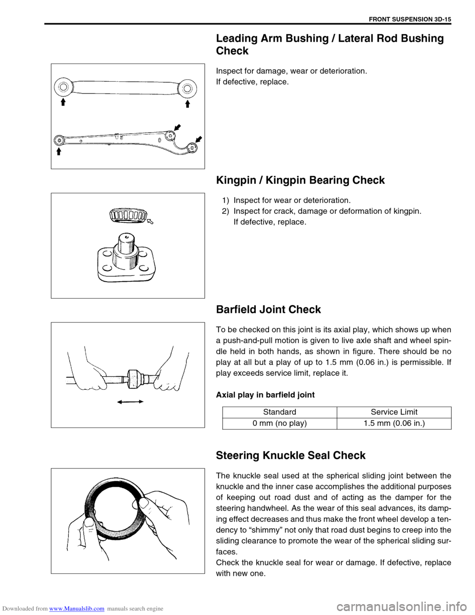
Leading Arm Bushing / Lateral Rod Bushing
Check
Inspect for damage, wear or deterioration.
If defective, replace.
Kingpin / Kingpin Bearing Check
1) Inspect for wear or deterioration.
2) Inspect for crack, damage or deformation of kingpin.
If defective, replace.
Barfield Joint Check
To be checked on this joint is its axial play, which shows up when
a push-and-pull motion is given to live axle shaft and wheel spin-
dle held in both hands, as shown in figure. There should be no
play at all but a play of up to 1.5 mm (0.06 in.) is permissible. If
play exceeds service limit, replace it.
Axial play in barfield joint
Steering Knuckle Seal Check
The knuckle seal used at the spherical sliding joint between the
knuckle and the inner case accomplishes the additional purposes
of keeping out road dust and of acting as the damper for the
steering handwheel. As the wear of this seal advances, its damp-
ing effect decreases and thus make the front wheel develop a ten-
dency to “shimmy” not only that road dust begins to creep into the
sliding clearance to promote the wear of the spherical sliding sur-
faces.
Check the knuckle seal for wear or damage. If defective, replace
with new one.
Standard Service Limit
0 mm (no play) 1.5 mm (0.06 in.)
Page 247 of 687
Downloaded from www.Manualslib.com manuals search engine 3F-4 WHEELS AND TIRES
Diagnosis
Diagnosis Table
Refer to “Diagnosis Table” in Section 3.
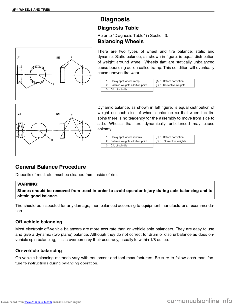
Balancing Wheels
There are two types of wheel and tire balance: static and
dynamic. Static balance, as shown in figure, is equal distribution
of weight around wheel. Wheels that are statically unbalanced
cause bouncing action called tramp. This condition will eventually
cause uneven tire wear.
Dynamic balance, as shown in left figure, is equal distribution of
weight on each side of wheel centerline so that when the tire
spins there is no tendency for the assembly to move from side to
side. Wheels that are dynamically unbalanced may cause
shimmy.
General Balance Procedure
Deposits of mud, etc. must be cleaned from inside of rim.
Tire should be inspected for any damage, then balanced according to equipment manufacturer’s recommenda-
tion.
Off-vehicle balancing
Most electronic off-vehicle balancers are more accurate than on-vehicle spin balancers. They are easy to use
and give a dynamic (two plane) balance. Although they do not correct for drum or disc unbalance as does on-
vehicle spin balancing, this is overcome by their accuracy, usually to within 1/8 ounce.
On-vehicle balancing
On-vehicle balancing methods vary with equipment and tool manufacturers. Be sure to follow each manufac-
turer’s instructions during balancing operation.
1. Heavy spot wheel tramp [A] : Before correction
2. Balance weights addition point [B] : Corrective weights
3. C/L of spindle
1. Heavy spot wheel shimmy [C] : Before correction
2. Balance weights addition point [D] : Corrective weights
3. C/L of spindle
WARNING:
Stones should be removed from tread in order to avoid operator injury during spin balancing and to
obtain good balance.
Page 280 of 687
Downloaded from www.Manualslib.com manuals search engine BRAKES 5-19
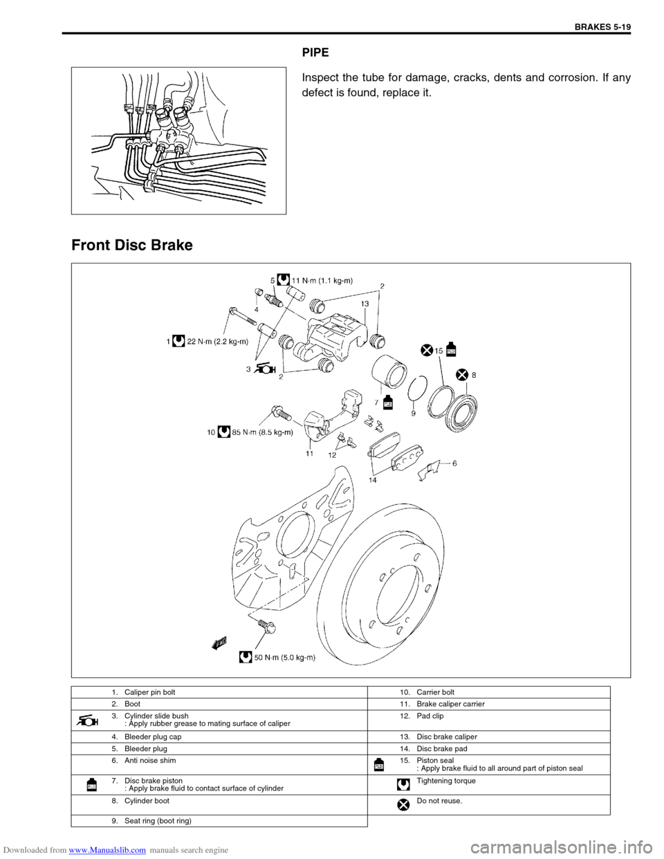
PIPE
Inspect the tube for damage, cracks, dents and corrosion. If any
defect is found, replace it.
Front Disc Brake
1. Caliper pin bolt 10. Carrier bolt
2. Boot11. Brake caliper carrier
3. Cylinder slide bush
: Apply rubber grease to mating surface of caliper12. Pad clip
4. Bleeder plug cap 13. Disc brake caliper
5. Bleeder plug 14. Disc brake pad
6. Anti noise shim 15. Piston seal
: Apply brake fluid to all around part of piston seal
7. Disc brake piston
: Apply brake fluid to contact surface of cylinderTightening torque
8. Cylinder bootDo not reuse.
9. Seat ring (boot ring)
Page 282 of 687
Downloaded from www.Manualslib.com manuals search engine BRAKES 5-21
INSTALLATION
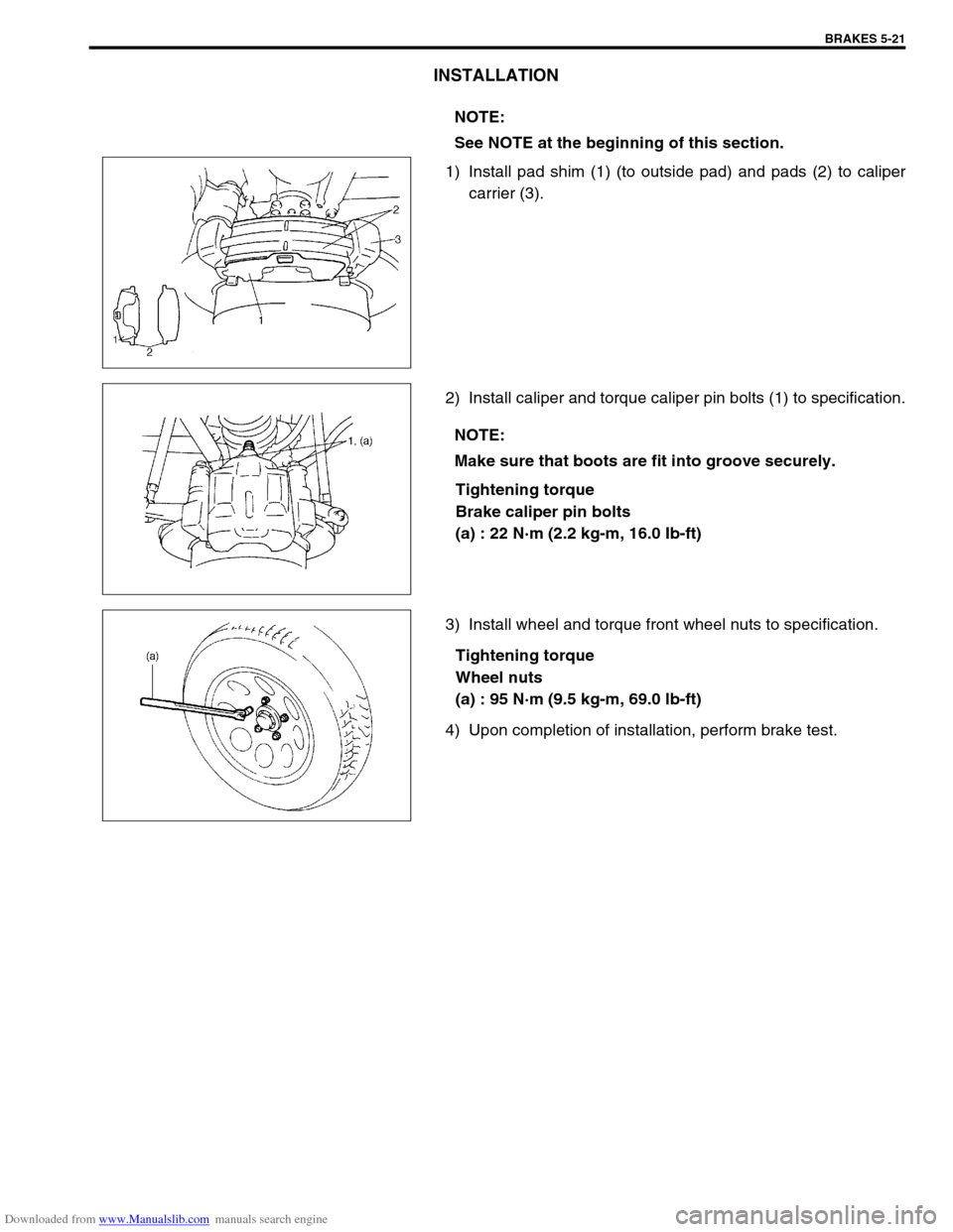
1) Install pad shim (1) (to outside pad) and pads (2) to caliper
carrier (3).
2) Install caliper and torque caliper pin bolts (1) to specification.
Tightening torque
Brake caliper pin bolts
(a) : 22 N·m (2.2 kg-m, 16.0 Ib-ft)
3) Install wheel and torque front wheel nuts to specification.
Tightening torque
Wheel nuts
(a) : 95 N·m (9.5 kg-m, 69.0 lb-ft)
4) Upon completion of installation, perform brake test.NOTE:
See NOTE at the beginning of this section.
NOTE:
Make sure that boots are fit into groove securely.
Page 482 of 687
Downloaded from www.Manualslib.com manuals search engine ENGINE MECHANICAL (M13 ENGINE) 6A1-1
6F1
6G
6H
6K
7A
7A1
7B1
7C1
7D
7E
7F
8A
8C
6A1
8E
9
9
10B
SECTION 6A1
ENGINE MECHANICAL (M13 ENGINE)
CONTENTS
General Description ......................................6A1-2
Engine ......................................................... 6A1-2
Engine Lubrication ...................................... 6A1-3
Diagnosis .......................................................6A1-4
Diagnosis Table .......................................... 6A1-4
Compression Check .................................... 6A1-4
Engine Vacuum Check ................................ 6A1-6
Oil Pressure Check ..................................... 6A1-7
Valve Lash (Clearance) ............................... 6A1-9
On-Vehicle Service......................................6A1-13
Air Cleaner Element .................................. 6A1-13
Air Cleaner Assembly ................................ 6A1-14
Knock Sensor ............................................ 6A1-14
Cylinder Head Cover ................................. 6A1-15
Throttle Body and Intake Manifold ............ 6A1-18
Exhaust Manifold ....................................... 6A1-21Oil Pan and Oil Pump Strainer .................. 6A1-24
Timing Chain Cover .................................. 6A1-28
Oil Pump ................................................... 6A1-33
Timing Chain and Chain Tensioner .......... 6A1-37
Camshaft, Tappet and Shim ..................... 6A1-42
Valves and Cylinder Head ........................ 6A1-48
Pistons, Piston Rings, Connecting
Rods and Cylinders................................... 6A1-62
Engine Mountings ..................................... 6A1-72
Unit Repair Overhaul .................................. 6A1-73
Engine Assembly ...................................... 6A1-73
Main Bearings, Crankshaft and Cylinder
Block ......................................................... 6A1-79
Required Service Material .......................... 6A1-93
Tightening Torque Specification ............... 6A1-93
Special Tool ................................................. 6A1-94
WARNING:
For vehicles equipped with Supplemental Restraint (Air Bag) System:
Service on and around the air bag system components or wiring must be performed only by an
authorized SUZUKI dealer. Refer to “Air Bag System Components and Wiring Location View” under
“General Description” in air bag system section in order to confirm whether you are performing ser-
vice on or near the air bag system components or wiring. Please observe all WARNINGS and “Ser-
vice Precautions” under “On-Vehicle Service” in air bag system section before performing service
on or around the air bag system components or wiring. Failure to follow WARNINGS could result in
unintentional activation of the system or could render the system inoperative. Either of these two
conditions may result in severe injury.
Technical service work must be started at least 90 seconds after the ignition switch is turned to the
“LOCK” position and the negative cable is disconnected from the battery. Otherwise, the system
may be activated by reserve energy in the Sensing and Diagnostic Module (SDM).
Page 490 of 687
Downloaded from www.Manualslib.com manuals search engine ENGINE MECHANICAL (M13 ENGINE) 6A1-9
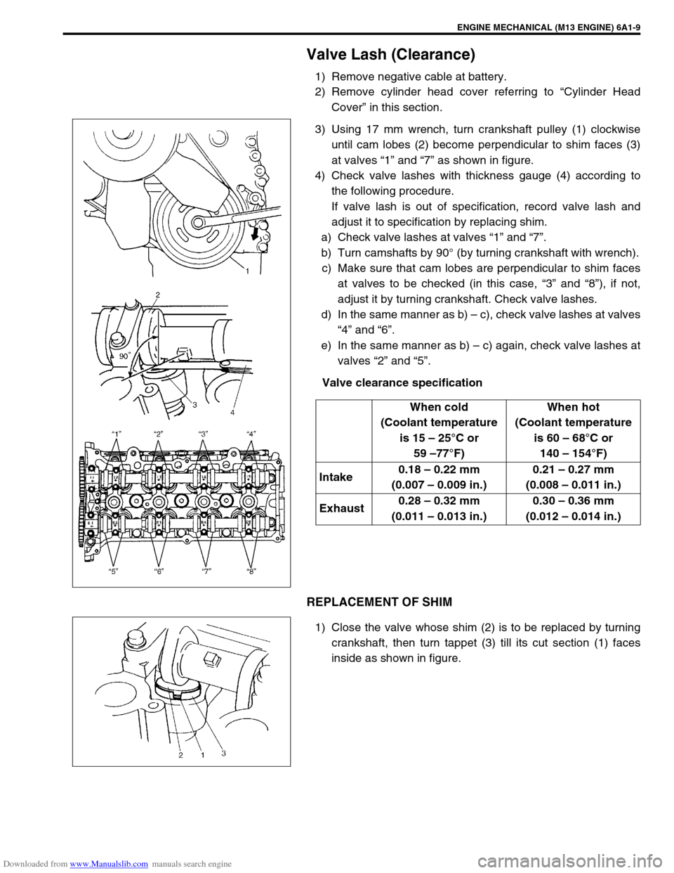
Valve Lash (Clearance)
1) Remove negative cable at battery.
2) Remove cylinder head cover referring to “Cylinder Head
Cover” in this section.
3) Using 17 mm wrench, turn crankshaft pulley (1) clockwise
until cam lobes (2) become perpendicular to shim faces (3)
at valves “1” and “7” as shown in figure.
4) Check valve lashes with thickness gauge (4) according to
the following procedure.
If valve lash is out of specification, record valve lash and
adjust it to specification by replacing shim.
a) Check valve lashes at valves “1” and “7”.
b) Turn camshafts by 90° (by turning crankshaft with wrench).
c) Make sure that cam lobes are perpendicular to shim faces
at valves to be checked (in this case, “3” and “8”), if not,
adjust it by turning crankshaft. Check valve lashes.
d) In the same manner as b) – c), check valve lashes at valves
“4” and “6”.
e) In the same manner as b) – c) again, check valve lashes at
valves “2” and “5”.
Valve clearance specification
REPLACEMENT OF SHIM
1) Close the valve whose shim (2) is to be replaced by turning
crankshaft, then turn tappet (3) till its cut section (1) faces
inside as shown in figure.When cold
(Coolant temperature
is 15 – 25°C or
59 –77°F)When hot
(Coolant temperature
is 60 – 68°C or
140 – 154°F)
Intake0.18 – 0.22 mm
(0.007 – 0.009 in.)0.21 – 0.27 mm
(0.008 – 0.011 in.)
Exhaust0.28 – 0.32 mm
(0.011 – 0.013 in.)0.30 – 0.36 mm
(0.012 – 0.014 in.)
Page 491 of 687
Downloaded from www.Manualslib.com manuals search engine 6A1-10 ENGINE MECHANICAL (M13 ENGINE)
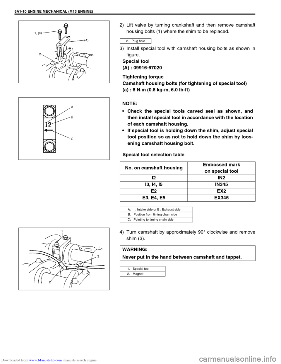
2) Lift valve by turning crankshaft and then remove camshaft
housing bolts (1) where the shim to be replaced.
3) Install special tool with camshaft housing bolts as shown in
figure.
Special tool
(A) : 09916-67020
Tightening torque
Camshaft housing bolts (for tightening of special tool)
(a) : 8 N·m (0.8 kg-m, 6.0 lb-ft)
Special tool selection table
4) Turn camshaft by approximately 90° clockwise and remove
shim (3).
2. Plug hole
NOTE:
Check the special tools carved seal as shown, and
then install special tool in accordance with the location
of each camshaft housing.
If special tool is holding down the shim, adjust special
tool position so as not to hold down the shim by loos-
ening camshaft housing bolt.
No. on camshaft housingEmbossed mark
on special tool
I2 IN2
I3, I4, I5 IN345
E2 EX2
E3, E4, E5 EX345
A: I : Intake side or E : Exhaust side
B: Position from timing chain side
C: Pointing to timing chain side
WARNING:
Never put in the hand between camshaft and tappet.
1. Special tool
2. Magnet