Signal SUZUKI JIMNY 2005 3.G Service Workshop Manual
[x] Cancel search | Manufacturer: SUZUKI, Model Year: 2005, Model line: JIMNY, Model: SUZUKI JIMNY 2005 3.GPages: 687, PDF Size: 13.38 MB
Page 1 of 687

Downloaded from www.Manualslib.com manuals search engine IMPORTANT
WARNING/CAUTION/NOTE
Please read this manual and follow its instructions carefully. To emphasize special information, the words
WARNING, CAUTION
and NOTE
have special meanings. Pay special attention to the messages highlighted by
these signal words.
WARNING:
Indicates a potential hazard that could result in death or injury.
CAUTION:
Indicates a potential hazard that could result in vehicle damage.
NOTE:
Indicates special information to make maintenance easier or instructions clearer.
WARNING:
This service manual is intended for authorized Suzuki dealers and qualified service mechanics only.
Inexperienced mechanics or mechanics without the proper tools and equipment may not be able to
properly perform the services described in this manual.
Improper repair may result in injury to the mechanic and may render the vehicle unsafe for the driver
and passengers.
WARNING:
For vehicles equipped with a Supplemental Restraint or Air Bag System:
• Service on and around the air bag system components or wiring must be performed only by an
authorized SUZUKI dealer. Refer to “Air Bag System Components and Wiring Location View” under
“General Description” in air bag system section in order to confirm whether you are performing ser-
vice on or near the air bag system components or wiring. Please observe all WARNINGS and “Ser-
vice Precautions” under “On-Vehicle Service” in air bag system section before performing service
on or around the air bag system components or wiring. Failure to follow WARNINGS could result in
unintentional activation of the system or could render the system inoperative. Either of these two
conditions may result in severe injury.
If the air bag system and another vehicle system both need repair, Suzuki recommends that the air
bag system be repaired first, to help avoid unintended air bag system activation.
Do not modify the steering wheel, instrument panel or any other air bag system component on or
around air bag system components or wiring. Modifications can adversely affect air bag system
performance and lead to injury.
If the vehicle will be exposed to temperatures over 93°C (200°F), for example, during a paint baking
process, remove the air bag system components, that is air bag or inflator modules, SDM and/or
seat belt with pretensioner, beforehand to avoid component damage or unintended activation.
Page 161 of 687
Downloaded from www.Manualslib.com manuals search engine 3C-8 STEERING WHEEL AND COLUMN
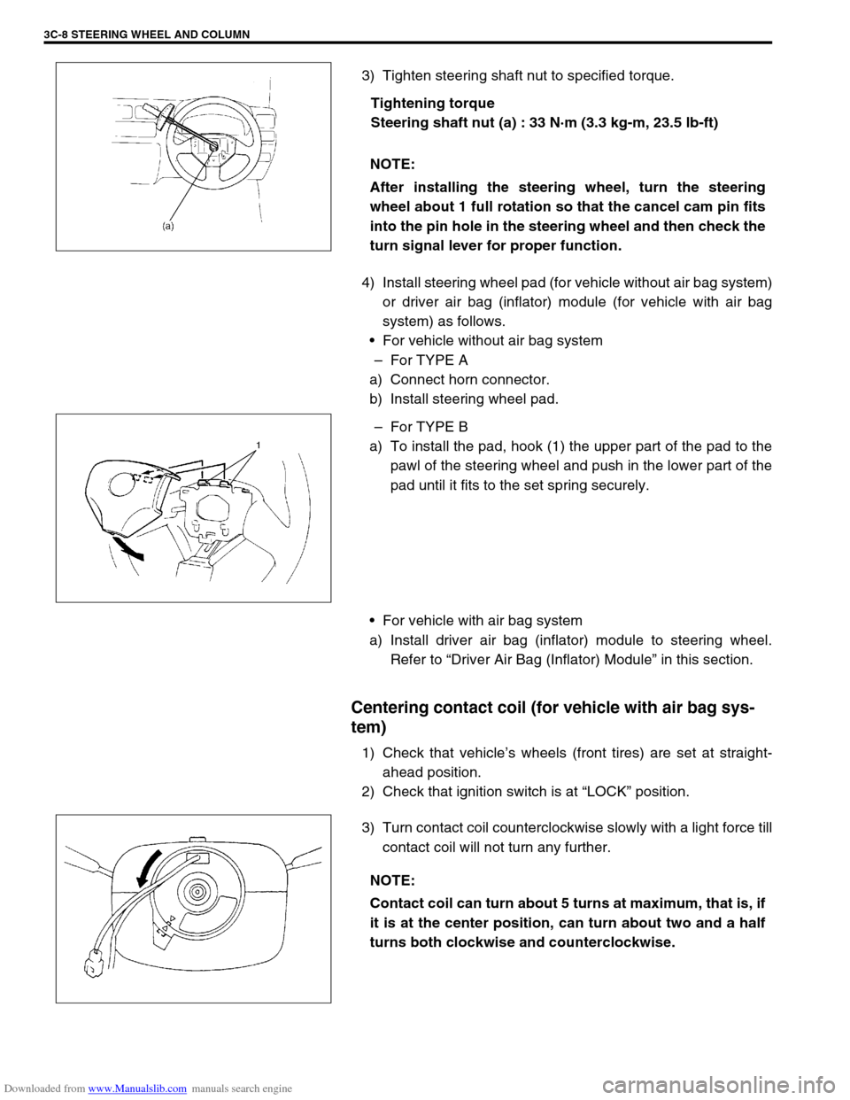
3) Tighten steering shaft nut to specified torque.
Tightening torque
Steering shaft nut (a) : 33 N·m (3.3 kg-m, 23.5 lb-ft)
4) Install steering wheel pad (for vehicle without air bag system)
or driver air bag (inflator) module (for vehicle with air bag
system) as follows.
For vehicle without air bag system
–For TYPE A
a) Connect horn connector.
b) Install steering wheel pad.
–For TYPE B
a) To install the pad, hook (1) the upper part of the pad to the
pawl of the steering wheel and push in the lower part of the
pad until it fits to the set spring securely.
For vehicle with air bag system
a) Install driver air bag (inflator) module to steering wheel.
Refer to “Driver Air Bag (Inflator) Module” in this section.
Centering contact coil (for vehicle with air bag sys-
tem)
1) Check that vehicle’s wheels (front tires) are set at straight-
ahead position.
2) Check that ignition switch is at “LOCK” position.
3) Turn contact coil counterclockwise slowly with a light force till
contact coil will not turn any further. NOTE:
After installing the steering wheel, turn the steering
wheel about 1 full rotation so that the cancel cam pin fits
into the pin hole in the steering wheel and then check the
turn signal lever for proper function.
NOTE:
Contact coil can turn about 5 turns at maximum, that is, if
it is at the center position, can turn about two and a half
turns both clockwise and counterclockwise.
Page 175 of 687
Downloaded from www.Manualslib.com manuals search engine 3D-2 FRONT SUSPENSION
General Description
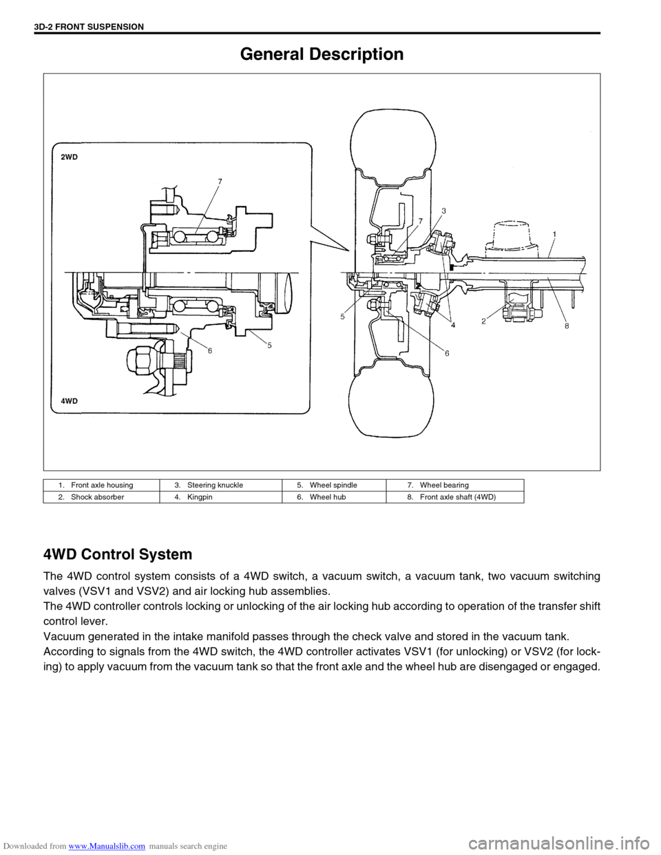
4WD Control System
The 4WD control system consists of a 4WD switch, a vacuum switch, a vacuum tank, two vacuum switching
valves (VSV1 and VSV2) and air locking hub assemblies.
The 4WD controller controls locking or unlocking of the air locking hub according to operation of the transfer shift
control lever.
Vacuum generated in the intake manifold passes through the check valve and stored in the vacuum tank.
According to signals from the 4WD switch, the 4WD controller activates VSV1 (for unlocking) or VSV2 (for lock-
ing) to apply vacuum from the vacuum tank so that the front axle and the wheel hub are disengaged or engaged.
1. Front axle housing 3. Steering knuckle 5. Wheel spindle 7. Wheel bearing
2. Shock absorber 4. Kingpin 6. Wheel hub 8. Front axle shaft (4WD)
Page 178 of 687

Downloaded from www.Manualslib.com manuals search engine FRONT SUSPENSION 3D-5
Components and Functions
Component Function
4WD switch When the transfer shift lever is shifted to 4L or 4H position from 2H, this switch
turns ON and cause the 4WD control system to turn ON.
4WD controller When the 4WD switch turns on, the 4WD controller activates VSV2 to lock the
air locking hubs and when it receives an “ON” signal from the vacuum switch, it
makes VSV2 to complete operation within 5 seconds and causes the 4WD indi-
cator light to light up.
If vacuum in the vacuum circuit fails to reach the specified level due to a leakage
in the vacuum circuit (when no “ON” signal is inputted from the vacuum switch),
the 4WD controller stops operation of VSV2 in 15 seconds and makes the 4WD
indicator light to flash to warn occurrence of a trouble.
When the 4WD switch turns off, the 4WD controller activates VSV1 for 10 sec-
onds to unlock the hubs and at the same time makes the 4WD indicator light
turn off.
VSV1 VSV1 operates according to the signal from the 4WD controller. When it is acti-
vated, the port opens and vacuum in the intake manifold is applied through the
vacuum circuit to unlock to the slide gear in the air locking hub. As a result, the
air locking hubs are unlocked.
VSV2 VSV2 operates according to the signal from the 4WD controller. When it is acti-
vated, the port opens and vacuum in the intake manifold is applied through the
vacuum circuit to lock to the slide gear in the air locking hub. As a result, the air
locking hubs are locked.
Vacuum switch When VSV2 receives the “ON” signal from 4WD switch, vacuum is applied
through its circuit to the vacuum switch. The vacuum switch turns on when it
detects vacuum exceeding 260 mmHg.
“4WD” indicator lamp It lights up when 4WD control system is in the 4WD mode.
It flashes to warn that locking hub operation has not completed (4WD control
system fails to shift 4WD).
Page 179 of 687
Downloaded from www.Manualslib.com manuals search engine 3D-6 FRONT SUSPENSION
OPERATION
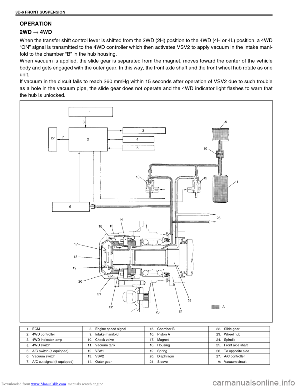
2WD
→ 4WD
When the transfer shift control lever is shifted from the 2WD (2H) position to the 4WD (4H or 4L) position, a 4WD
“ON” signal is transmitted to the 4WD controller which then activates VSV2 to apply vacuum in the intake mani-
fold to the chamber “B” in the hub housing.
When vacuum is applied, the slide gear is separated from the magnet, moves toward the center of the vehicle
body and gets engaged with the outer gear. In this way, the front axle shaft and the front wheel hub rotate as one
unit.
If vacuum in the circuit fails to reach 260 mmHg within 15 seconds after operation of VSV2 due to such trouble
as a hole in the vacuum pipe, the slide gear does not operate and the 4WD indicator light flashes to warn that
the hub is unlocked.
1. ECM 8. Engine speed signal 15. Chamber B 22. Slide gear
2. 4WD controller 9. Intake manifold 16. Piston A 23. Wheel hub
3. 4WD indicator lamp 10. Check valve 17. Magnet 24. Spindle
4.4WD switch 11. Vacuum tank 18. Housing 25. Front axle shaft
5. A/C switch (if equipped) 12. VSV1 19. Spring 26. To opposite side
6. Vacuum switch 13. VSV2 20. Diaphragm 27. A/C controller
7. A/C cut signal (if equipped) 14. Outer gear 21. Sleeve A: Vacuum circuit
Page 180 of 687
Downloaded from www.Manualslib.com manuals search engine FRONT SUSPENSION 3D-7
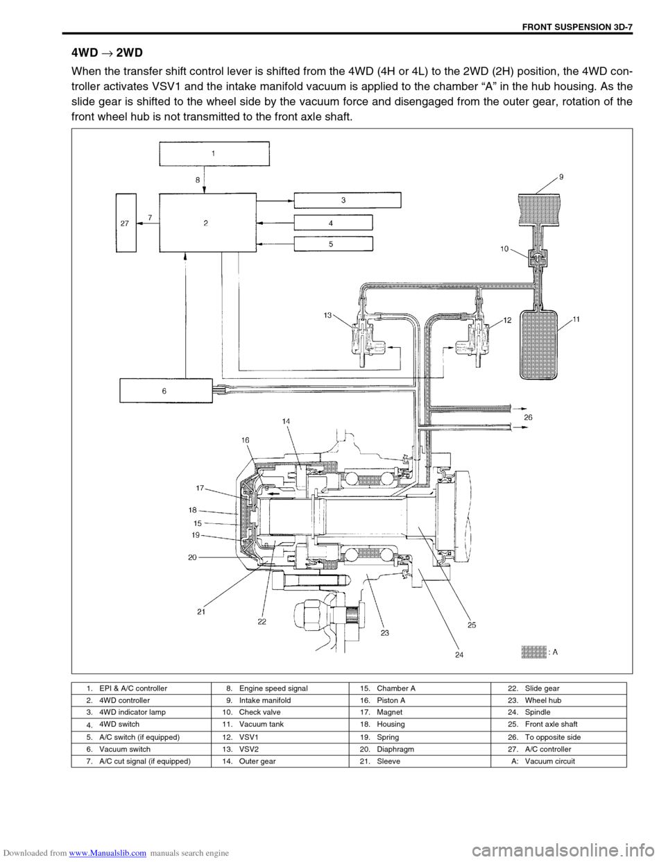
4WD
→ 2WD
When the transfer shift control lever is shifted from the 4WD (4H or 4L) to the 2WD (2H) position, the 4WD con-
troller activates VSV1 and the intake manifold vacuum is applied to the chamber “A” in the hub housing. As the
slide gear is shifted to the wheel side by the vacuum force and disengaged from the outer gear, rotation of the
front wheel hub is not transmitted to the front axle shaft.
1. EPI & A/C controller 8. Engine speed signal 15. Chamber A 22. Slide gear
2. 4WD controller 9. Intake manifold 16. Piston A 23. Wheel hub
3. 4WD indicator lamp 10. Check valve 17. Magnet 24. Spindle
4.4WD switch 11. Vacuum tank 18. Housing 25. Front axle shaft
5. A/C switch (if equipped) 12. VSV1 19. Spring 26. To opposite side
6. Vacuum switch 13. VSV2 20. Diaphragm 27. A/C controller
7. A/C cut signal (if equipped) 14. Outer gear 21. Sleeve A: Vacuum circuit
Page 319 of 687
Downloaded from www.Manualslib.com manuals search engine 5E-2 ANTILOCK BRAKE SYSTEM (ABS)
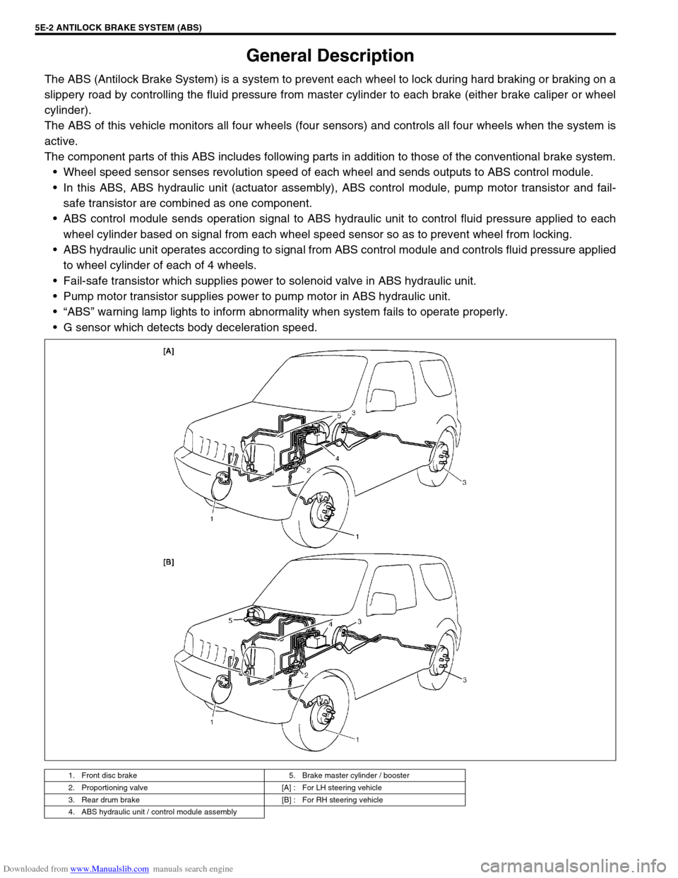
General Description
The ABS (Antilock Brake System) is a system to prevent each wheel to lock during hard braking or braking on a
slippery road by controlling the fluid pressure from master cylinder to each brake (either brake caliper or wheel
cylinder).
The ABS of this vehicle monitors all four wheels (four sensors) and controls all four wheels when the system is
active.
The component parts of this ABS includes following parts in addition to those of the conventional brake system.
Wheel speed sensor senses revolution speed of each wheel and sends outputs to ABS control module.
In this ABS, ABS hydraulic unit (actuator assembly), ABS control module, pump motor transistor and fail-
safe transistor are combined as one component.
ABS control module sends operation signal to ABS hydraulic unit to control fluid pressure applied to each
wheel cylinder based on signal from each wheel speed sensor so as to prevent wheel from locking.
ABS hydraulic unit operates according to signal from ABS control module and controls fluid pressure applied
to wheel cylinder of each of 4 wheels.
Fail-safe transistor which supplies power to solenoid valve in ABS hydraulic unit.
Pump motor transistor supplies power to pump motor in ABS hydraulic unit.
“ABS” warning lamp lights to inform abnormality when system fails to operate properly.
G sensor which detects body deceleration speed.
1. Front disc brake 5. Brake master cylinder / booster
2. Proportioning valve [A] : For LH steering vehicle
3. Rear drum brake [B] : For RH steering vehicle
4. ABS hydraulic unit / control module assembly
Page 330 of 687

Downloaded from www.Manualslib.com manuals search engine ANTILOCK BRAKE SYSTEM (ABS) 5E-13
TERMINAL CIRCUIT
A1 Idle up signal
A2 Stop lamp switch
A3 Right front wheel speed sensor (+)
A4 Right front wheel speed sensor (–)
A5–
A6 Right rear wheel speed sensor (–)
A7 Right rear wheel speed sensor (+)
A8–
A9–
A10–
A11 G sensor signal
A12 Diagnosis switch terminal
A13 G sensor ground
A14“ABS” warning lamp
A15 Left front wheel speed sensor (+)
A16 Left front wheel speed sensor (–)
A17 4WD switch (for 4WD model only)
A18 Ignition switch
A19 Left rear wheel speed sensor (+)
A20 Left rear wheel speed sensor (–)
A21 Data link connector
A22 Ground (for ABS pump motor)
A23 ABS pump motor power supply
A24 Ground (for ABS control module)
A25 Solenoid valve power supply
Wire color
B : Black G/W : Green / White R/W : Red / White
B/BI : Black / Blue Lg/B : Light green / Black W/Bl : White / Blue
B/W : Black / White Lg/R : Light green / Red W/G : White / Green
B/Or : Black / Orange Or : Orange W/R : White / Red
Bl : Blue Or/B : Orange / Black Y : Yellow
Bl/W : Blue / White P/B : Pink / Black Y/B : Yellow / Black
G : Green P/G : Pink / Green
G/B : Green / Black R/Bl : Red / Blue
Page 335 of 687
Downloaded from www.Manualslib.com manuals search engine 5E-18 ANTILOCK BRAKE SYSTEM (ABS)
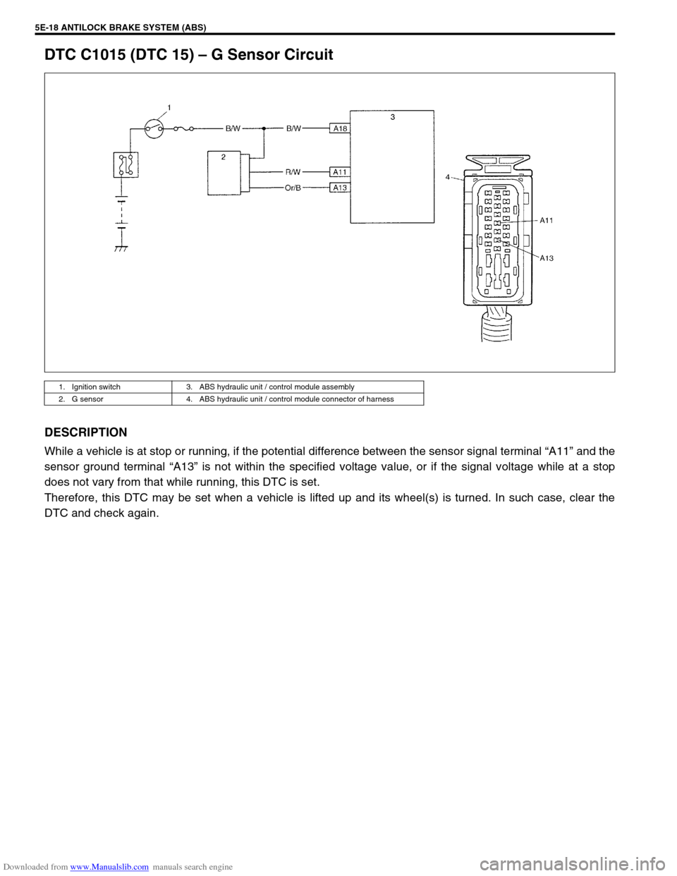
DTC C1015 (DTC 15) – G Sensor Circuit
DESCRIPTION
While a vehicle is at stop or running, if the potential difference between the sensor signal terminal “A11” and the
sensor ground terminal “A13” is not within the specified voltage value, or if the signal voltage while at a stop
does not vary from that while running, this DTC is set.
Therefore, this DTC may be set when a vehicle is lifted up and its wheel(s) is turned. In such case, clear the
DTC and check again.
1. Ignition switch 3. ABS hydraulic unit / control module assembly
2. G sensor 4. ABS hydraulic unit / control module connector of harness
Page 338 of 687
Downloaded from www.Manualslib.com manuals search engine ANTILOCK BRAKE SYSTEM (ABS) 5E-21
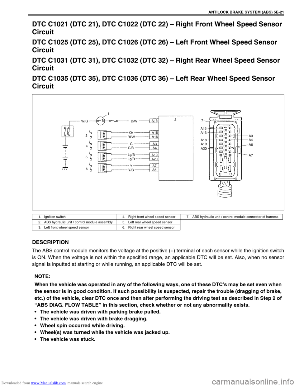
DTC C1021 (DTC 21), DTC C1022 (DTC 22) – Right Front Wheel Speed Sensor
Circuit
DTC C1025 (DTC 25), DTC C1026 (DTC 26) – Left Front Wheel Speed Sensor
Circuit
DTC C1031 (DTC 31), DTC C1032 (DTC 32) – Right Rear Wheel Speed Sensor
Circuit
DTC C1035 (DTC 35), DTC C1036 (DTC 36) – Left Rear Wheel Speed Sensor
Circuit
DESCRIPTION
The ABS control module monitors the voltage at the positive (+) terminal of each sensor while the ignition switch
is ON. When the voltage is not within the specified range, an applicable DTC will be set. Also, when no sensor
signal is inputted at starting or while running, an applicable DTC will be set.
1. Ignition switch 4. Right front wheel speed sensor 7. ABS hydraulic unit / control module connector of harness
2. ABS hydraulic unit / control module assembly 5. Left rear wheel speed sensor
3. Left front wheel speed sensor 6. Right rear wheel speed sensor
NOTE:
When the vehicle was operated in any of the following ways, one of these DTC’s may be set even when
the sensor is in good condition. If such possibility is suspected, repair the trouble (dragging of brake,
etc.) of the vehicle, clear DTC once and then after performing the driving test as described in Step 2 of
“ABS DIAG. FLOW TABLE” in this section, check whether or not any abnormality exists.
The vehicle was driven with parking brake pulled.
The vehicle was driven with brake dragging.
Wheel spin occurred while driving.
Wheel(s) was turned while the vehicle was jacked up.
The vehicle was stuck.