radio SUZUKI MARUTI 2005 1.G Owners Manual
[x] Cancel search | Manufacturer: SUZUKI, Model Year: 2005, Model line: MARUTI, Model: SUZUKI MARUTI 2005 1.GPages: 136, PDF Size: 2.93 MB
Page 3 of 136
Downloaded from www.Manualslib.com manuals search engine 383K
MODIFICATION WARNING
w ww w
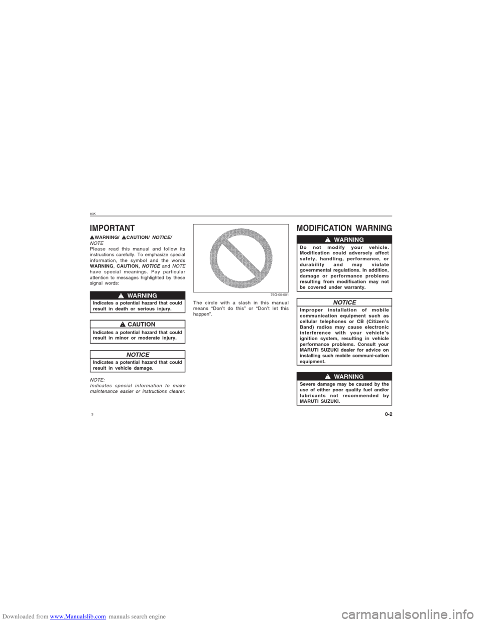
w WARNING
Do not modify your vehicle.
Modification could adversely affect
safety, handling, performance, or
durability and may violate
governmental regulations. In addition,
damage or performance problems
resulting from modification may not
be covered under warranty.
0-2
t tt t
tWARNING/
t tt t
tCAUTION/
NOTICE/
NOTE
Please read this manual and follow its
instructions carefully. To emphasize special
information, the symbol and the words
WARNING, CAUTION,
NOTICE
and
NOTE
have special meanings. Pay particular
attention to messages highlighted by these
signal words:IMPORTANT
w ww w
w WARNING
Indicates a potential hazard that could
result in death or serious injury.
Indicates a potential hazard that could
result in minor or moderate injury.
t tt t
t CAUTION
NOTICE
Indicates a potential hazard that could
result in vehicle damage.NOTE:
Indicates special information to make
maintenance easier or instructions clearer.
76G-00-001
The circle with a slash in this manual
means “Don’t do this” or “Don’t let this
happen”.
NOTICE
Improper installation of mobile
communication equipment such as
cellular telephones or CB (Citizen’s
Band) radios may cause electronic
interference with your vehicle’s
ignition system, resulting in vehicle
performance problems. Consult your
MARUTI SUZUKI dealer for advice on
installing such mobile communi-cation
equipment.
w ww w
w WARNING
Severe damage may be caused by the
use of either poor quality fuel and/or
lubricants not recommended by
MARUTI SUZUKI.
Page 17 of 136
Downloaded from www.Manualslib.com manuals search engine 1783K
BEFORE DRIVING
4-5
Be sure the doors are locked after you
operate the “LOCK” button. If no door is
opened within about 30 seconds after the
“UNLOCK” button is operated, the doors will
automatically lock again.NOTE:
The maximum operating distance of the
keyless entry system transmitter is about
5 m (16 ft.), but this can vary depending
on the surroundings, especially near
other transmitting devices such as radio
towers or CB (citizen’s band).
The door locks can not be operated with
the transmitter if the ignition switch is in
a position other than “LOCK”, or the igni-
tion key is inserted in the ignition switch.
When any door is open, the door locks
can be operated only unlock with the
transmitter, and the turn signal light will
not flash.
If you lose one of the transmitters, con-
tact your MARUTI SUZUKI authorized
dealer as soon as possible for a replace-
ment. Be sure to have your dealer pro-
gram the new transmitter code in your
vehicle’s memory so that the old code
is erased.
CAUTION
The transmitter is a sensitive elec-
tronic instrument. To avoid damaging
the transmitter:
Do not expose it to impacts, mois-
ture or high temperature such as by
leaving it on the dashboard under
direct sunlight.
Keep the transmitter away from
magnetic objects such as a televi-
sion.
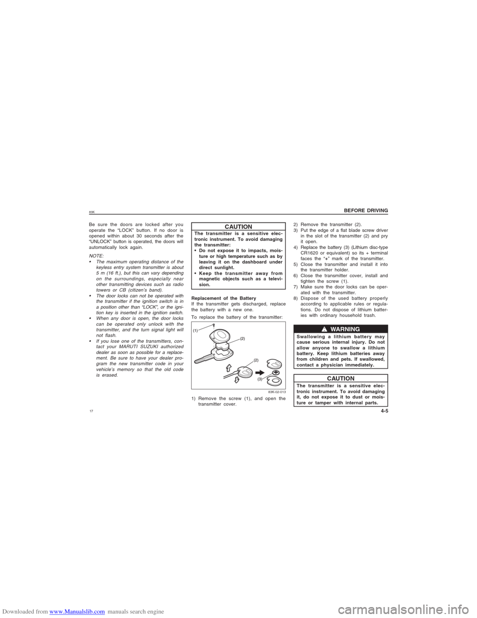
Replacement of the Battery
If the transmitter gets discharged, replace
the battery with a new one.
To replace the battery of the transmitter:
83K-02-013
1) Remove the screw (1), and open the
transmitter cover.2) Remove the transmitter (2).
3) Put the edge of a flat blade screw driver
in the slot of the transmitter (2) and pry
it open.
4) Replace the battery (3) (Lithium disc-type
CR1620 or equivalent) so its + terminal
faces the “+” mark of the transmitter.
5) Close the transmitter and install it into
the transmitter holder.
6) Close the transmitter cover, install and
tighten the screw (1).
7) Make sure the door locks can be oper-
ated with the transmitter.
8) Dispose of the used battery properly
according to applicable rules or regula-
tions. Do not dispose of lithium batter-
ies with ordinary household trash.
CAUTIONw ww w
w WARNING
Swallowing a lithium battery may
cause serious internal injury. Do not
allow anyone to swallow a lithium
battery. Keep lithium batteries away
from children and pets. If swallowed,
contact a physician immediately.
The transmitter is a sensitive elec-
tronic instrument. To avoid damaging
it, do not expose it to dust or mois-
ture or tamper with internal parts.
Page 19 of 136
Downloaded from www.Manualslib.com manuals search engine 1983K
BEFORE DRIVING
4-7
while you are entering/exiting the vehicle.
a) Press and release the Key Unlock but-
ton.
b) Two Siren chrip and two indicator light-
flashes will confirm Disarm and Unlock.
c) Doors will get Unlock and vehicle will get
disarmed.
d) Visible theft warning LED on security
switch will flash fastly.
83K-02-020
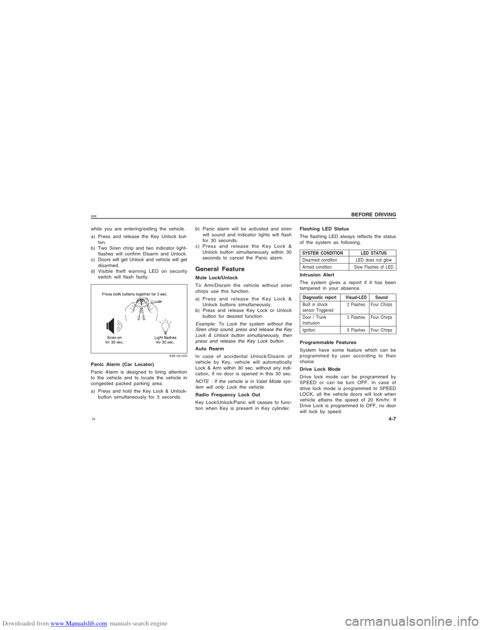
Panic Alarm (Car Locator)
Panic Alarm is designed to bring attention
to the vehicle and to locate the vehicle in
congested packed parking area.
a) Press and hold the Key Lock & Unlock-
button simultaneously for 3 seconds.b) Panic alarm will be activated and siren
will sound and indicator lights will flash
for 30 seconds.
c) Press and release the Key Lock &
Unlock button simultaneously within 30
seconds to cancel the Panic alarm.
General FeatureMute Lock/Unlock
To Arm/Disram the vehicle without siren
chirps use this function.
a) Press and release the Key Lock &
Unlock buttons simultaneously.
b) Press and release Key Lock or Unlock
button for desired function.Example: To Lock the system without the
Siren chirp sound, press and release the Key
Lock & Unlock button simultaneously, then
press and release the Key Lock button.Auto Rearm
In case of accidental Unlock/Disarm of
vehicle by Key, vehicle will automatically
Lock & Arm within 30 sec. without any indi-
cation, if no door is opened in this 30 sec.NOTE : If the vehicle is in Valet Mode sys-
tem will only Lock the vehicle.Radio Frequency Lock Out
Key Lock/Unlock/Panic will ceases to func-
tion when Key is present in Key cylinder.Flashing LED Status
The flashing LED always reflects the status
of the system as following.
SYSTEM CONDITION LED STATUS
Disarmed condition LED does not glow
Armed condition Slow Flashes of LEDDiagnostic report Visual-LED Sound
Built in shock 2 Flashes Four Chirps
sensor Triggered
Door / Trunk 3 Flashes Four Chirps
Instrusion
Ignition 5 Flashes Four ChirpsIntrusion Alert
The system gives a report if it has been
tampered in your absence.
Programmable Features
System have some feature which can be
programmed by user according to their
choice.
Drive Lock Mode
Drive lock mode can be programmed by
SPEED or can be turn OFF. In case of
drive lock mode is programmed to SPEED
LOCK, all the vehicle doors will lock when
vehicle attains the speed of 20 Km/hr. If
Drive Lock is programmed to OFF, no door
will lock by speed.
Page 23 of 136
Downloaded from www.Manualslib.com manuals search engine 2383K
BEFORE DRIVING
4-11
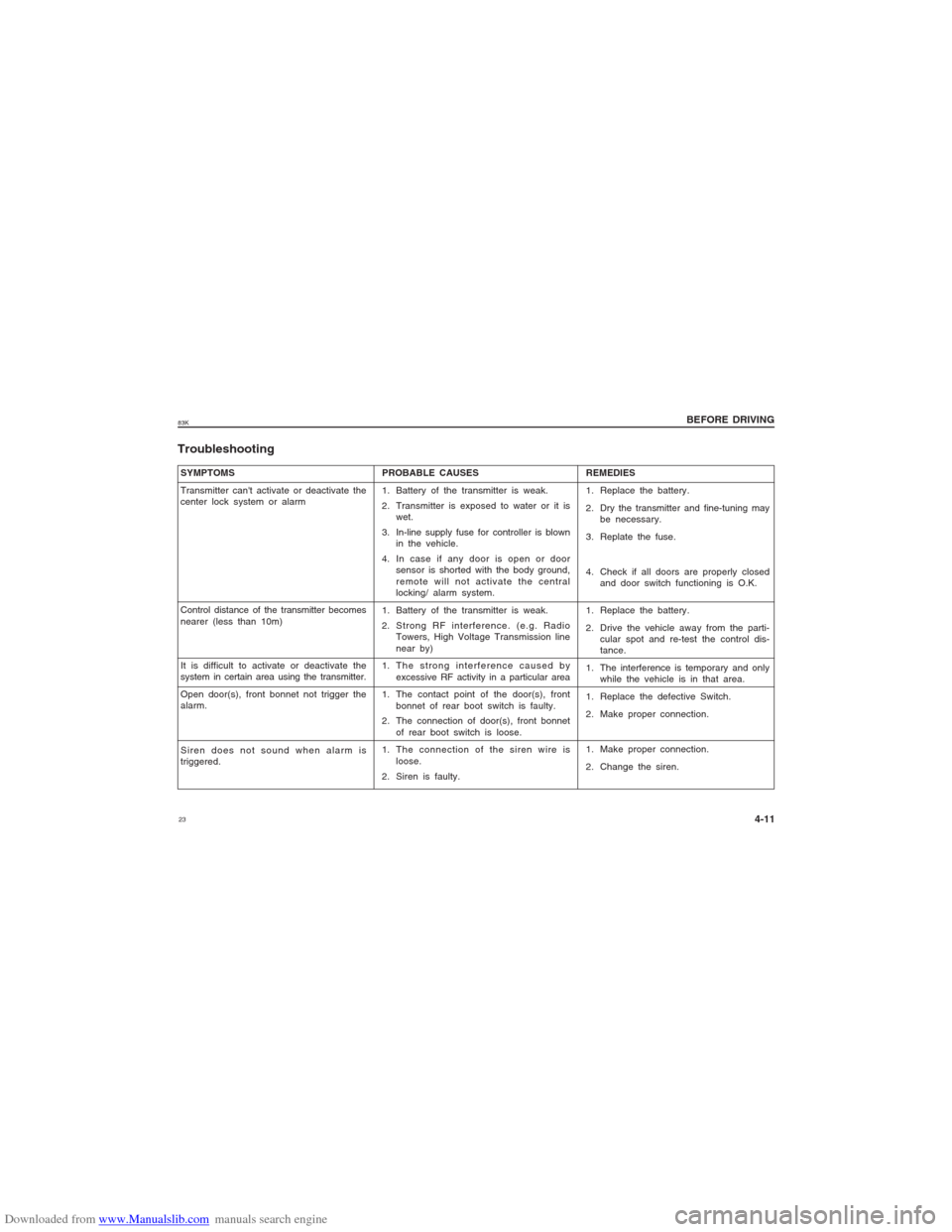
SYMPTOMS
Transmitter can't activate or deactivate the
center lock system or alarm
Control distance of the transmitter becomes
nearer (less than 10m)
It is difficult to activate or deactivate the
system in certain area using the transmitter.
Open door(s), front bonnet not trigger the
alarm.
Siren does not sound when alarm is
triggered.Troubleshooting
PROBABLE CAUSES
1. Battery of the transmitter is weak.
2. Transmitter is exposed to water or it is
wet.
3. In-line supply fuse for controller is blown
in the vehicle.
4. In case if any door is open or door
sensor is shorted with the body ground,
remote will not activate the central
locking/ alarm system.
1. Battery of the transmitter is weak.
2. Strong RF interference. (e.g. Radio
Towers, High Voltage Transmission line
near by)
1. The strong interference caused by
excessive RF activity in a particular area
1. The contact point of the door(s), front
bonnet of rear boot switch is faulty.
2. The connection of door(s), front bonnet
of rear boot switch is loose.
1. The connection of the siren wire is
loose.
2. Siren is faulty.REMEDIES
1. Replace the battery.
2. Dry the transmitter and fine-tuning may
be necessary.
3. Replate the fuse.
4. Check if all doors are properly closed
and door switch functioning is O.K.
1. Replace the battery.
2. Drive the vehicle away from the parti-
cular spot and re-test the control dis-
tance.
1. The interference is temporary and only
while the vehicle is in that area.
1. Replace the defective Switch.
2. Make proper connection.
1. Make proper connection.
2. Change the siren.
Page 58 of 136
Downloaded from www.Manualslib.com manuals search engine 5883K
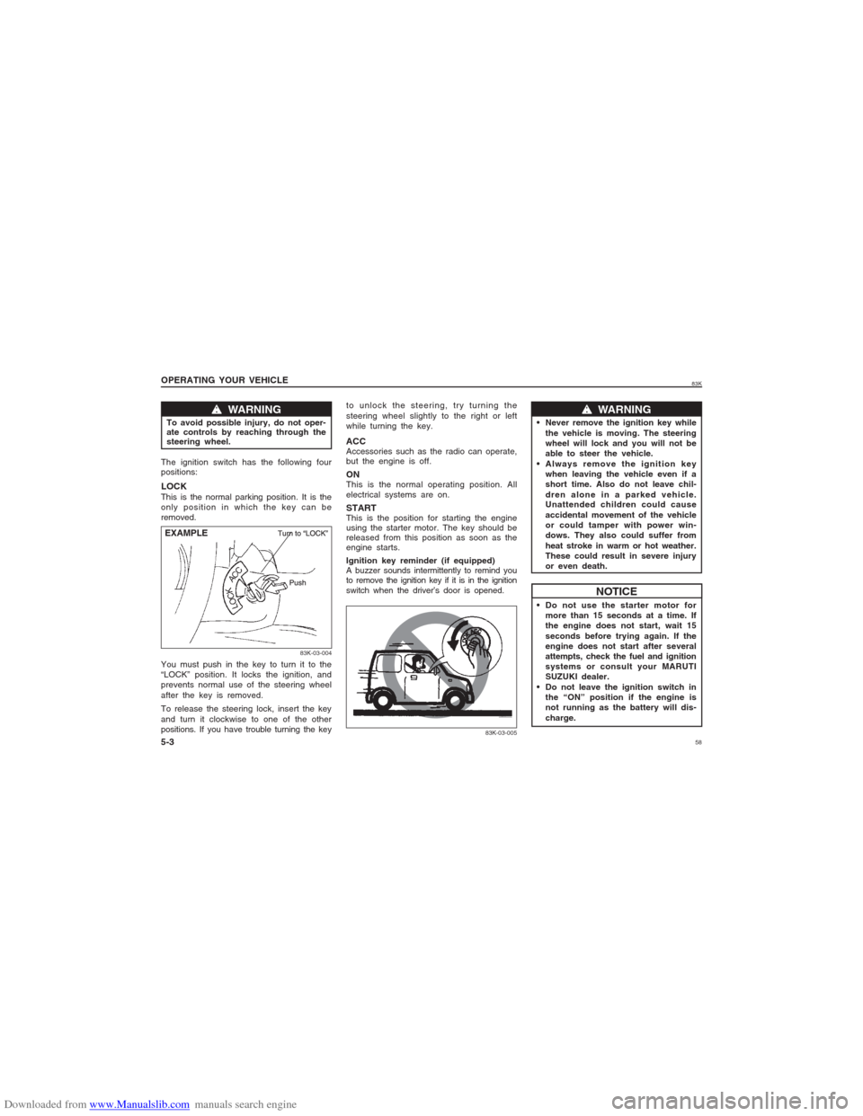
w ww w
w WARNING
To avoid possible injury, do not oper-
ate controls by reaching through the
steering wheel.
83K-03-004
EXAMPLE OPERATING YOUR VEHICLE
5-3The ignition switch has the following four
positions:LOCKThis is the normal parking position. It is the
only position in which the key can be
removed.
You must push in the key to turn it to the
“LOCK” position. It locks the ignition, and
prevents normal use of the steering wheel
after the key is removed.
To release the steering lock, insert the key
and turn it clockwise to one of the other
positions. If you have trouble turning the keyto unlock the steering, try turning the
steering wheel slightly to the right or left
while turning the key.
ACCAccessories such as the radio can operate,
but the engine is off.ONThis is the normal operating position. All
electrical systems are on.STARTThis is the position for starting the engine
using the starter motor. The key should be
released from this position as soon as the
engine starts.
Ignition key reminder (if equipped)
A buzzer sounds intermittently to remind you
to remove the ignition key if it is in the ignition
switch when the driver’s door is opened.
w ww w
w WARNING
Never remove the ignition key while
the vehicle is moving. The steering
wheel will lock and you will not be
able to steer the vehicle.
Always remove the ignition key
when leaving the vehicle even if a
short time. Also do not leave chil-
dren alone in a parked vehicle.
Unattended children could cause
accidental movement of the vehicle
or could tamper with power win-
dows. They also could suffer from
heat stroke in warm or hot weather.
These could result in severe injury
or even death.
NOTICE
Do not use the starter motor for
more than 15 seconds at a time. If
the engine does not start, wait 15
seconds before trying again. If the
engine does not start after several
attempts, check the fuel and ignition
systems or consult your MARUTI
SUZUKI dealer.
Do not leave the ignition switch in
the “ON” position if the engine is
not running as the battery will dis-
charge.
83K-03-005
Page 74 of 136
Downloaded from www.Manualslib.com manuals search engine 7483K
OTHER CONTROLS AND EQUIPMENT
Heating and Air Conditioning System........................................................................... 7-1
Manual Heating and Air Conditioning System............................................................. 7-1
Radio Antenna..................................................................................................................... 7-4
Remote Audio Controls (if equipped)............................................................................ 7-4
Fuel Filler Cap.................................................................................................................... 7-5
Engine Bonnet..................................................................................................................... 7-6
Sun Visor............................................................................................................................. 7-6
Interior Light Switch ..........................................................................................................7-7
Accessory Socket (if equipped)...................................................................................... 7-7
Assist Grips (if equipped)................................................................................................ 7-8
Glove Box............................................................................................................................ 7-8
Instrument Panel Upper Tray........................................................................................... 7-8
Cup Holder........................................................................................................................... 7-9
Front Seat Back Pocket (if equipped)........................................................................... 7-9
Underseat Tray (if equipped)........................................................................................... 7-9
Shopping Hook (if equipped).........................................................................................7-10
Luggage Area Cover (if equipped)...............................................................................7-10
Frame Hooks..................................................................................................................... 7-10
OTHER CONTROLS AND EQUIPMENT
Page 78 of 136
Downloaded from www.Manualslib.com manuals search engine 7883K
OTHER CONTROLS AND EQUIPMENT
7-4Using the wrong refrigerant may
damage your air conditioning system.
Use R-134a only. Do not mix or replace
the R-134a with other refrigerants.
CAUTION
NOTE:
If you need maximum demisting:
set the air flow selector to “DEMIST”,
set the blower speed selector to HIGH,
adjust the temperature selector to the
HOT end,
turn on the “A/C” switch, and
adjust the side outlets so the air blows
on the side windows.MaintenanceIf you do not use the air conditioner for a
long period, such as during winter, it may
not give the best performance when you
start using it again. To help maintain opti-
mum performance and durability of your air
conditioner, it needs to be run periodically.
Operate the air conditioner at least once a
month for one minute with the engine idling.
This circulates the refrigerant and oil and
helps protect the internal components.NOTE:
Your vehicle uses the air conditioning
refrigerant HFC-134a, commonly called “R-
134a”. Only R-134a should be used in your
vehicle.
Audio System (if equipped)Refer supplementary manual for audio
system (if equipped), provided along with
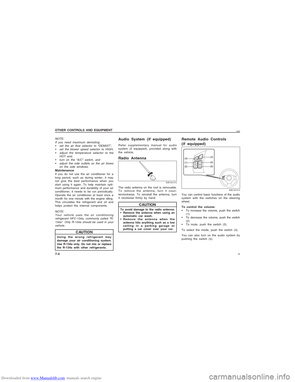
the vehicle.Radio Antenna
83K-05-013
To avoid damage to the radio antenna:
Remove the antenna when using an
automatic car wash.
Remove the antenna when the
antenna hits anything such as a low
ceiling in a parking garage or
putting a car cover over your car.
CAUTION
Remote Audio Controls
(if equipped)
83K-05-014
You can control basic functions of the audio
system with the switches on the steering
wheel.
To control the volume:
To increase the volume, push the switch
(1).
To decrease the volume, push the switch
(2).
To mute, push the switch (3).
To select the mode, push the switch (4).
You can also turn on the audio system by
pushing the switch (4). The radio antenna on the roof is removable.
To remove the antenna, turn it coun-
terclockwise. To reinstall the antenna, turn
it clockwise firmly by hand.
Page 79 of 136
Downloaded from www.Manualslib.com manuals search engine 7983K
OTHER CONTROLS AND EQUIPMENT
7-5
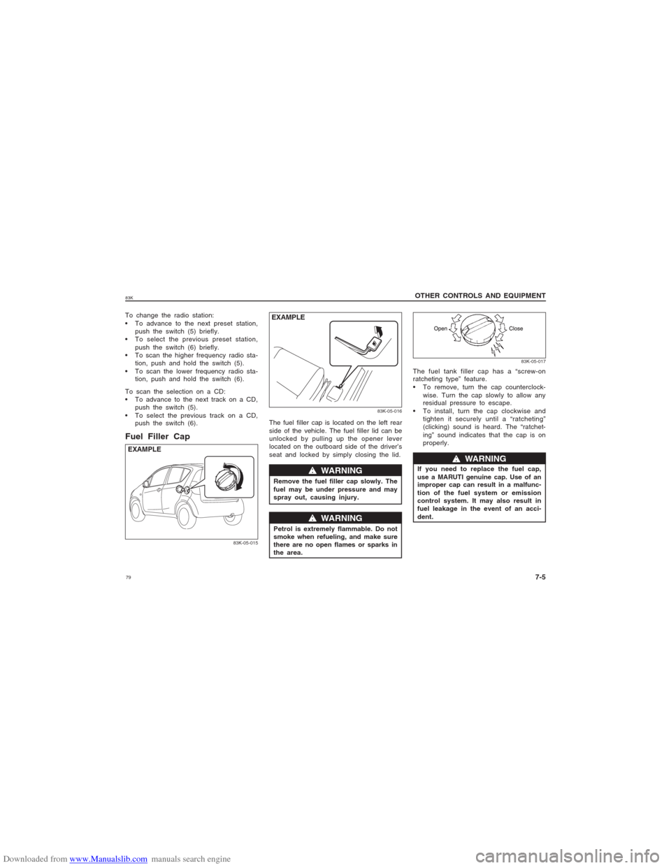
To change the radio station:
To advance to the next preset station,
push the switch (5) briefly.
To select the previous preset station,
push the switch (6) briefly.
To scan the higher frequency radio sta-
tion, push and hold the switch (5).
To scan the lower frequency radio sta-
tion, push and hold the switch (6).
To scan the selection on a CD:
To advance to the next track on a CD,
push the switch (5).
To select the previous track on a CD,
push the switch (6).Fuel Filler Cap
83K-05-015
EXAMPLE
83K-05-016
w ww w
w WARNING
Remove the fuel filler cap slowly. The
fuel may be under pressure and may
spray out, causing injury.
w ww w
w WARNING
Petrol is extremely flammable. Do not
smoke when refueling, and make sure
there are no open flames or sparks in
the area.
EXAMPLE
83K-05-017
The fuel tank filler cap has a “screw-on
ratcheting type” feature.
To remove, turn the cap counterclock-
wise. Turn the cap slowly to allow any
residual pressure to escape.
To install, turn the cap clockwise and
tighten it securely until a “ratcheting”
(clicking) sound is heard. The “ratchet-
ing” sound indicates that the cap is on
properly. The fuel filler cap is located on the left rear
side of the vehicle. The fuel filler lid can be
unlocked by pulling up the opener lever
located on the outboard side of the driver’s
seat and locked by simply closing the lid.
If you need to replace the fuel cap,
use a MARUTI genuine cap. Use of an
improper cap can result in a malfunc-
tion of the fuel system or emission
control system. It may also result in
fuel leakage in the event of an acci-
dent.
w ww w
w WARNING
Page 114 of 136
Downloaded from www.Manualslib.com manuals search engine 11483K
INSPECTION AND MAINTENANCE
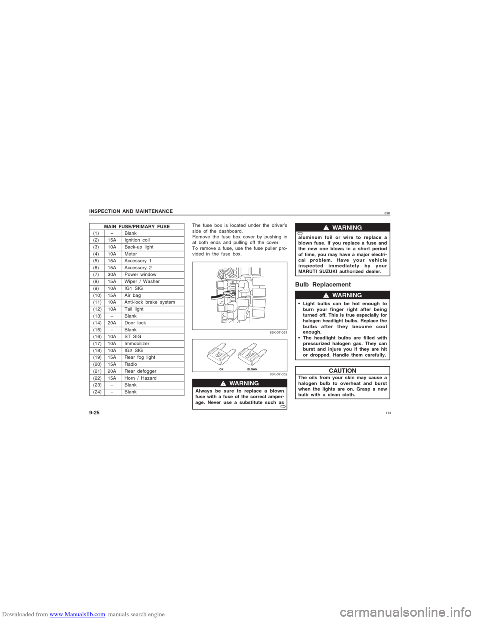
9-25(1) – Blank
(2) 15A Ignition coil
(3) 10A Back-up light
(4) 10A Meter
(5) 15A Accessory 1
(6) 15A Accessory 2
(7) 30A Power window
(8) 15A Wiper / Washer
(9) 10A IG1 SIG
(10) 15A Air bag
(11) 10A Anti-lock brake system
(12) 10ATail light
(13) – Blank
(14) 20A Door lock
(15) – Blank
(16) 10A ST SIG
(17) 10A Immobilizer
(18) 10A IG2 SIG
(19) 15A Rear fog light
(20) 15ARadio
(21) 20A Rear defogger
(22) 15A Horn / Hazard
(23) – Blank
(24) – BlankMAIN FUSE/PRIMARY FUSE
83K-07-051
The fuse box is located under the driver’s
side of the dashboard.
Remove the fuse box cover by pushing in
at both ends and pulling off the cover.
To remove a fuse, use the fuse puller pro-
vided in the fuse box.
83K-07-052
w ww w
w WARNING
Always be sure to replace a blown
fuse with a fuse of the correct amper-
age. Never use a substitute such as
V VV V
V
w ww w
w WARNING
aluminum foil or wire to replace a
blown fuse. If you replace a fuse and
the new one blows in a short period
of time, you may have a major electri-
cal problem. Have your vehicle
inspected immediately by your
MARUTI SUZUKI authorized dealer.V VV V
V
Bulb Replacement Light bulbs can be hot enough to
burn your finger right after being
turned off. This is true especially for
halogen headlight bulbs. Replace the
bulbs after they become cool
enough.
The headlight bulbs are filled with
pressurized halogen gas. They can
burst and injure you if they are hit
or dropped. Handle them carefully.
w ww w
w WARNING
The oils from your skin may cause a
halogen bulb to overheat and burst
when the lights are on. Grasp a new
bulb with a clean cloth.
CAUTION
Page 132 of 136
Downloaded from www.Manualslib.com manuals search engine 13283K
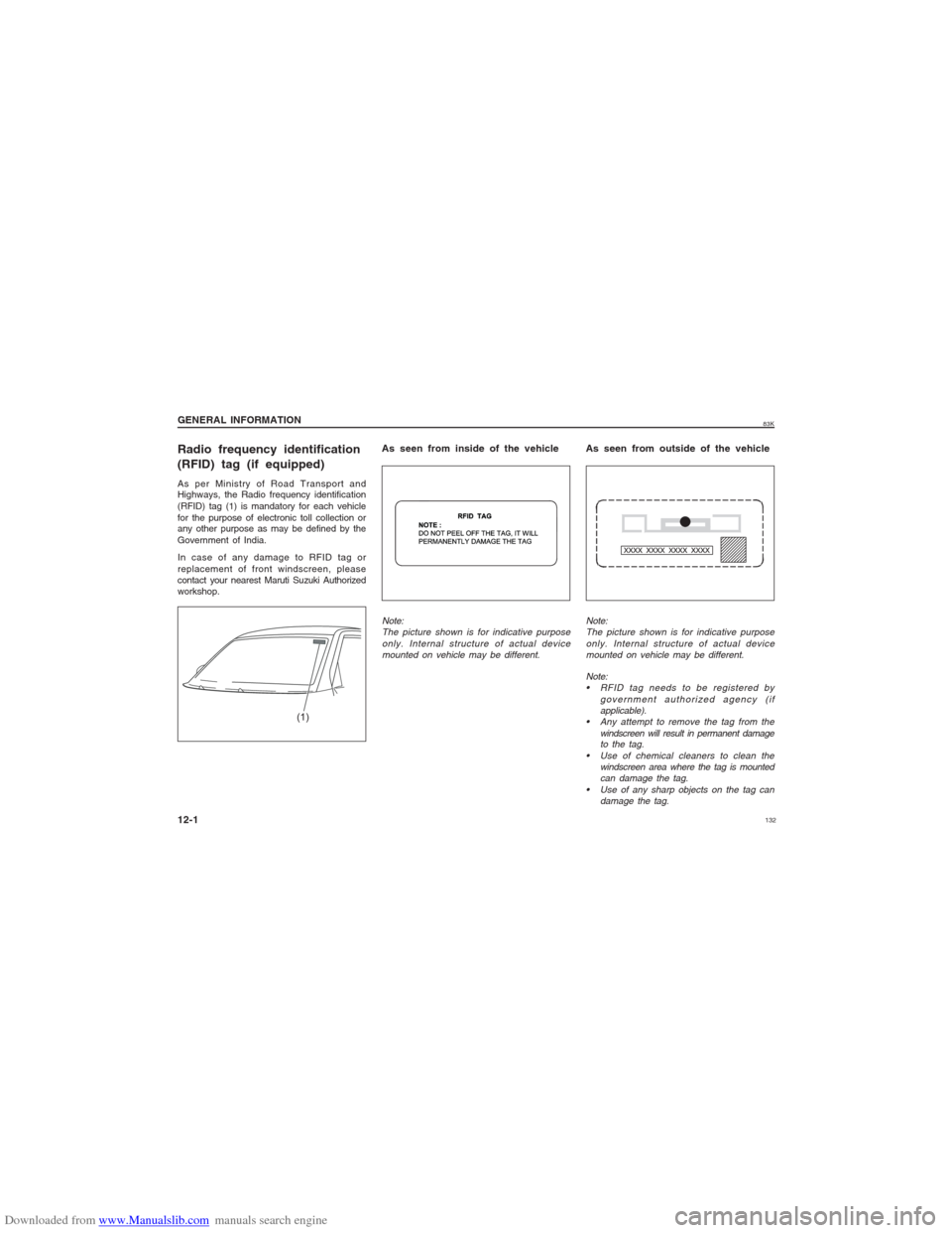
Radio frequency identification
(RFID) tag (if equipped)As per Ministry of Road Transport and
Highways, the Radio frequency identification
(RFID) tag (1) is mandatory for each vehicle
for the purpose of electronic toll collection or
any other purpose as may be defined by the
Government of India.
In case of any damage to RFID tag or
replacement of front windscreen, please
contact your nearest Maruti Suzuki Authorized
workshop.
Note:
RFID tag needs to be registered by
government authorized agency (if
applicable).
Any attempt to remove the tag from the
windscreen will result in permanent damage
to the tag.
Use of chemical cleaners to clean the
windscreen area where the tag is mounted
can damage the tag.
Use of any sharp objects on the tag can
damage the tag.
(1)
As seen from outside of the vehicle As seen from inside of the vehicleNote:
The picture shown is for indicative purpose
only. Internal structure of actual device
mounted on vehicle may be different. Note:
The picture shown is for indicative purpose
only. Internal structure of actual device
mounted on vehicle may be different.
GENERAL INFORMATION
12-1