Air SUZUKI SWIFT 2000 1.G RG413 Service Workshop Manual
[x] Cancel search | Manufacturer: SUZUKI, Model Year: 2000, Model line: SWIFT, Model: SUZUKI SWIFT 2000 1.GPages: 698, PDF Size: 16.01 MB
Page 187 of 698
3C-14 STEERING WHEEL AND COLUMN
INSPECTION
INSTALLATION
1) Be sure that front wheels and steering wheel are in straight
forward state.
If steering lock assembly (ignition switch) is removed, install
it, referring to “STEERING LOCK ASSEMBLY (IGNITION
SWITCH)” in this section.
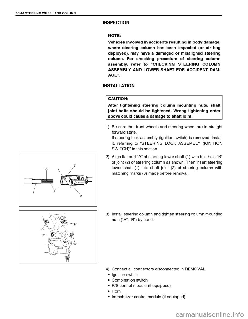
2) Align flat part “A” of steering lower shaft (1) with bolt hole “B”
of joint (2) of steering column as shown. Then insert steering
lower shaft (1) into shaft joint (2) of steering column with
matching marks (3) made before removal.
3) Install steering column and tighten steering column mounting
nuts (“A”, “B”) by hand.
4) Connect all connectors disconnected in REMOVAL.
Ignition switch
Combination switch
P/S control module (if equipped)
Horn
Immobilizer control module (if equipped) NOTE:
Vehicles involved in accidents resulting in body damage,
where steering column has been impacted (or air bag
deployed), may have a damaged or misaligned steering
column. For checking procedure of steering column
assembly, refer to “CHECKING STEERING COLUMN
ASSEMBLY AND LOWER SHAFT FOR ACCIDENT DAM-
AGE”.
CAUTION:
After tightening steering column mounting nuts, shaft
joint bolts should be tightened. Wrong tightening order
above could cause a damage to shaft joint.
Page 188 of 698
STEERING WHEEL AND COLUMN 3C-15
5) If contact coil and combination switch assembly is removed,
install it.
Refer to “CONTACT COIL AND COMBINATION SWITCH
ASSEMBLY”.
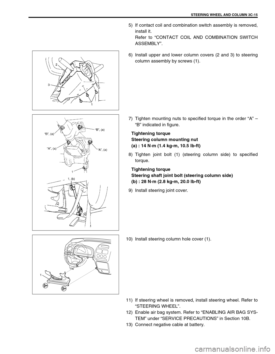
6) Install upper and lower column covers (2 and 3) to steering
column assembly by screws (1).
7) Tighten mounting nuts to specified torque in the order “A” –
“B” indicated in figure.
Tightening torque
Steering column mounting nut
(a) : 14 N·m (1.4 kg-m, 10.5 lb-ft)
8) Tighten joint bolt (1) (steering column side) to specified
torque.
Tightening torque
Steering shaft joint bolt (steering column side)
(b) : 28 N·m (2.8 kg-m, 20.0 lb-ft)
9) Install steering joint cover.
10) Install steering column hole cover (1).
11) If steering wheel is removed, install steering wheel. Refer to
“STEERING WHEEL”.
12) Enable air bag system. Refer to “ENABLING AIR BAG SYS-
TEM” under “SERVICE PRECAUTIONS” in Section 10B.
13) Connect negative cable at battery.
1
Page 191 of 698
3C-18 STEERING WHEEL AND COLUMN
INSTALLATION
1) Be sure that front wheels and steering wheel are in straight
forward state.
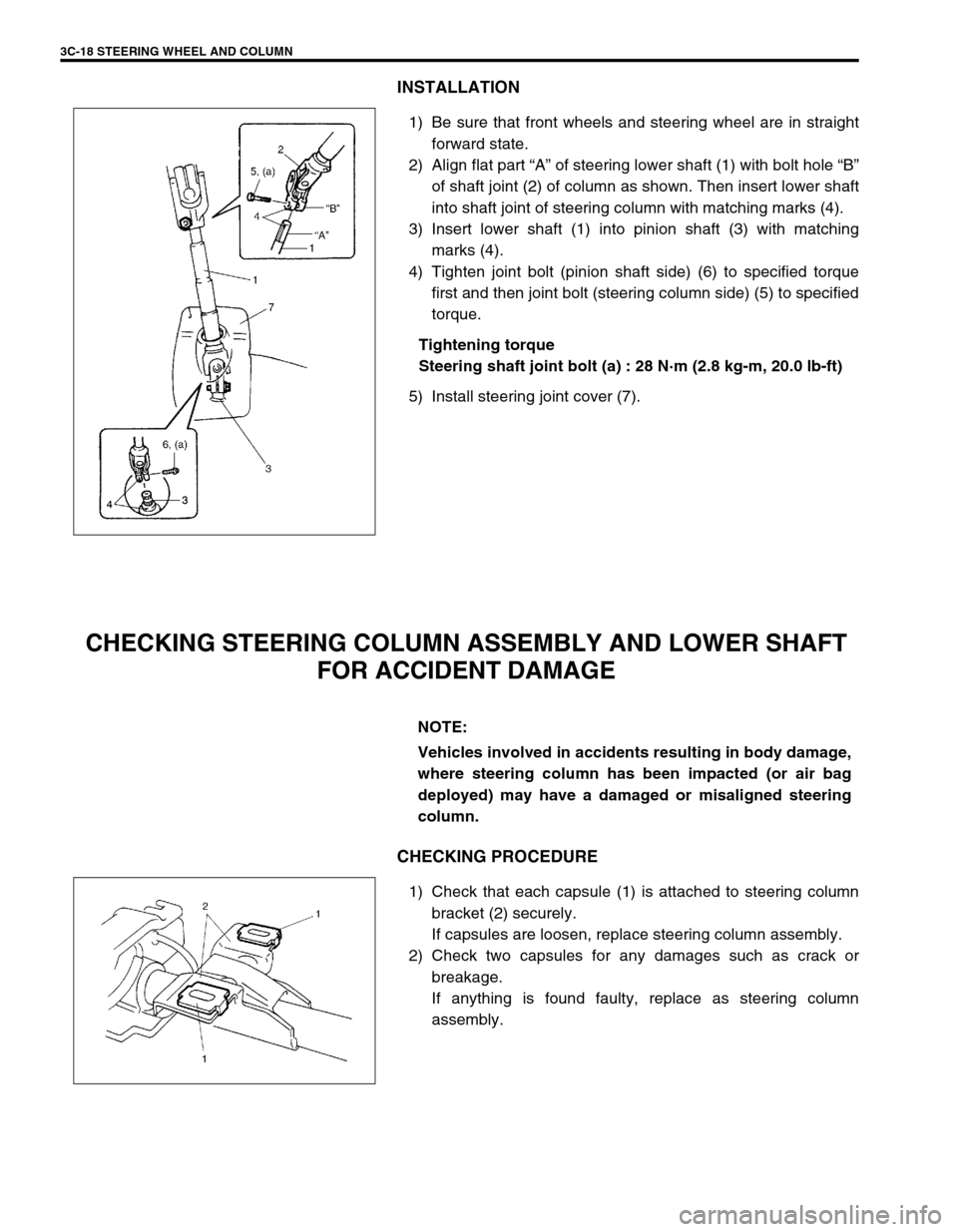
2) Align flat part “A” of steering lower shaft (1) with bolt hole “B”
of shaft joint (2) of column as shown. Then insert lower shaft
into shaft joint of steering column with matching marks (4).
3) Insert lower shaft (1) into pinion shaft (3) with matching
marks (4).
4) Tighten joint bolt (pinion shaft side) (6) to specified torque
first and then joint bolt (steering column side) (5) to specified
torque.
Tightening torque
Steering shaft joint bolt (a) : 28 N·m (2.8 kg-m, 20.0 lb-ft)
5) Install steering joint cover (7).
CHECKING STEERING COLUMN ASSEMBLY AND LOWER SHAFT
FOR ACCIDENT DAMAGE
CHECKING PROCEDURE
1) Check that each capsule (1) is attached to steering column
bracket (2) securely.
If capsules are loosen, replace steering column assembly.
2) Check two capsules for any damages such as crack or
breakage.
If anything is found faulty, replace as steering column
assembly.
NOTE:
Vehicles involved in accidents resulting in body damage,
where steering column has been impacted (or air bag
deployed) may have a damaged or misaligned steering
column.
Page 194 of 698
FRONT SUSPENSION 3D-1
6F1
6F2
6G
1A
6K
7A
7A1
7B1
7C1
3D
7F
8A
8B
8C
8D
8E
9
10
10A
10B
SECTION 3D
FRONT SUSPENSION
CONTENTS
GENERAL DESCRIPTION .............................. 3D-1
DIAGNOSIS ..................................................... 3D-3
STABILIZER BAR AND/OR BUSHING
CHECK ......................................................... 3D-3
STRUT ASSEMBLY CHECK ....................... 3D-3
SUSPENSION CONTROL ARM / STEERING
KNUCKLE CHECK ....................................... 3D-4
SUSPENSION CONTROL ARM BUSHING
CHECK ......................................................... 3D-4
SUSPENSION CONTROL ARM JOINT
CHECK ......................................................... 3D-4
FRONT SUSPENSION FASTENERS
CHECK ......................................................... 3D-5WHEEL DISC, NUT AND BEARING
CHECK ........................................................ 3D-5
ON-VEHICLE SERVICE .................................. 3D-6
STRUT ASSEMBLY..................................... 3D-6
STABILIZER BAR AND/OR BUSHINGS ..... 3D-9
WHEEL HUB AND STEERING
KNUCKLE .................................................. 3D-11
SUSPENSION CONTROL ARM /
BUSHING................................................... 3D-16
REQUIRED SERVICE MATERIAL................ 3D-19
SPECIAL TOOL ............................................ 3D-19
GENERAL DESCRIPTION
The front suspension is the strut type independent suspension. The upper end of a strut is anchored to the vehi-
cle body by a strut support. The strut and strut support are isolated by a rubber mount. A strut bearing is also
installed a little lower to the rubber mount.
The lower end of the strut is connected to the upper end of a steering knuckle and lower end of knuckle is
attached to the stud of a ball joint which is incorporated in a unit with a suspension control arm. And connected
to this steering knuckle is the tie rod end.
Thus, movement of the steering wheel is transmitted to the tie rod end and then to the knuckle, eventually caus-
ing the wheel-and-tire to move. In this operation, with the movement of the knuckle, the strut also rotates by
means of the strut bearing and lower ball joint.NOTE:
All front suspension fasteners are an important attaching part in that it could affect the perfor-
mance of vital parts and systems, and/or could result in major repair expense. They must be
replaced with one of the same part number or with an equivalent part if replacement becomes nec-
essary. Do not use a replacement part of lesser quality or substitute design. Torque values must be
used as specified during reassembly to assure proper retention of this part.
Never attempt to heat, quench or straighten any front suspension part. Replace it with a new part or
damage to the part may result.
Page 214 of 698
REAR SUSPENSION 3E-1
6F1
6F2
6G
1A
6K
7A
7A1
7B1
7C1
3E
8A
8B
8C
8D
8E
9
10
10A
10B
SECTION 3E
REAR SUSPENSION
CONTENTS
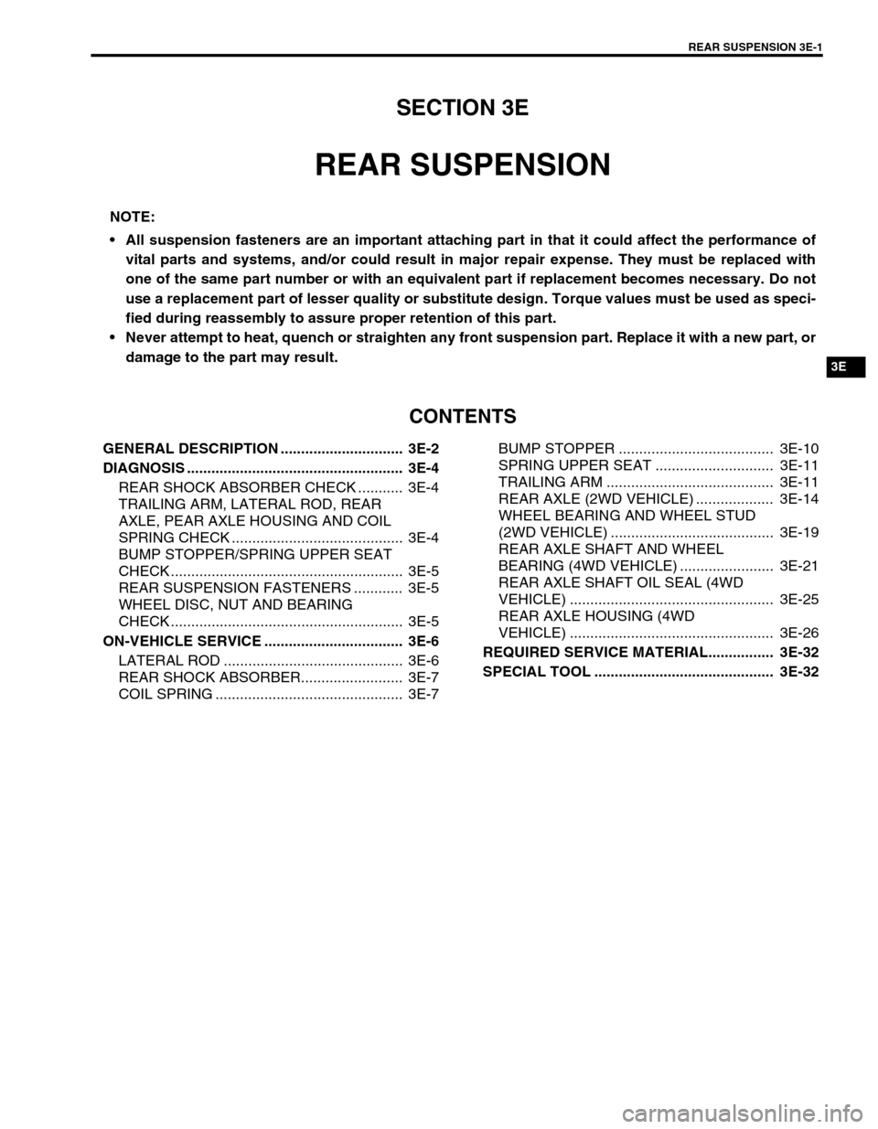
GENERAL DESCRIPTION .............................. 3E-2
DIAGNOSIS ..................................................... 3E-4
REAR SHOCK ABSORBER CHECK ........... 3E-4
TRAILING ARM, LATERAL ROD, REAR
AXLE, PEAR AXLE HOUSING AND COIL
SPRING CHECK .......................................... 3E-4
BUMP STOPPER/SPRING UPPER SEAT
CHECK ......................................................... 3E-5
REAR SUSPENSION FASTENERS ............ 3E-5
WHEEL DISC, NUT AND BEARING
CHECK ......................................................... 3E-5
ON-VEHICLE SERVICE .................................. 3E-6
LATERAL ROD ............................................ 3E-6
REAR SHOCK ABSORBER......................... 3E-7
COIL SPRING .............................................. 3E-7BUMP STOPPER ...................................... 3E-10
SPRING UPPER SEAT ............................. 3E-11
TRAILING ARM ......................................... 3E-11
REAR AXLE (2WD VEHICLE) ................... 3E-14
WHEEL BEARING AND WHEEL STUD
(2WD VEHICLE) ........................................ 3E-19
REAR AXLE SHAFT AND WHEEL
BEARING (4WD VEHICLE) ....................... 3E-21
REAR AXLE SHAFT OIL SEAL (4WD
VEHICLE) .................................................. 3E-25
REAR AXLE HOUSING (4WD
VEHICLE) .................................................. 3E-26
REQUIRED SERVICE MATERIAL................ 3E-32
SPECIAL TOOL ............................................ 3E-32
NOTE:
All suspension fasteners are an important attaching part in that it could affect the performance of
vital parts and systems, and/or could result in major repair expense. They must be replaced with
one of the same part number or with an equivalent part if replacement becomes necessary. Do not
use a replacement part of lesser quality or substitute design. Torque values must be used as speci-
fied during reassembly to assure proper retention of this part.
Never attempt to heat, quench or straighten any front suspension part. Replace it with a new part, or
damage to the part may result.
Page 246 of 698
WHEELS AND TIRES 3F-1
6F1
6F2
6G
3F
8A
8B
8C
8D
8E
9
10
10A
10B
SECTION 3F
WHEELS AND TIRES
CONTENTS
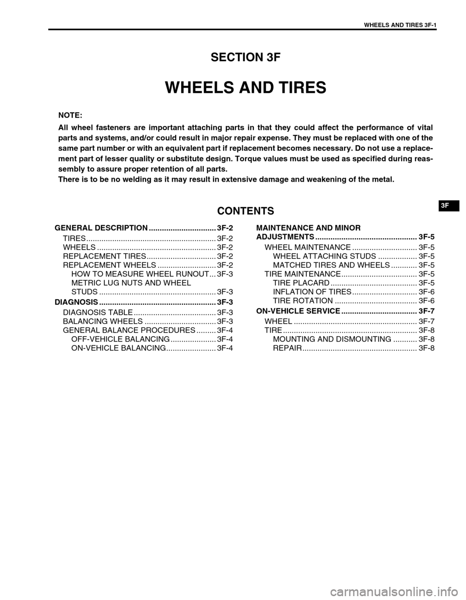
GENERAL DESCRIPTION ............................... 3F-2
TIRES ............................................................ 3F-2
WHEELS ....................................................... 3F-2
REPLACEMENT TIRES ................................ 3F-2
REPLACEMENT WHEELS ........................... 3F-2
HOW TO MEASURE WHEEL RUNOUT... 3F-3
METRIC LUG NUTS AND WHEEL
STUDS ...................................................... 3F-3
DIAGNOSIS ...................................................... 3F-3
DIAGNOSIS TABLE ...................................... 3F-3
BALANCING WHEELS ................................. 3F-3
GENERAL BALANCE PROCEDURES ......... 3F-4
OFF-VEHICLE BALANCING ..................... 3F-4
ON-VEHICLE BALANCING....................... 3F-4MAINTENANCE AND MINOR
ADJUSTMENTS ............................................... 3F-5
WHEEL MAINTENANCE .............................. 3F-5
WHEEL ATTACHING STUDS .................. 3F-5
MATCHED TIRES AND WHEELS ............ 3F-5
TIRE MAINTENANCE................................... 3F-5
TIRE PLACARD ........................................ 3F-5
INFLATION OF TIRES .............................. 3F-6
TIRE ROTATION ...................................... 3F-6
ON-VEHICLE SERVICE ................................... 3F-7
WHEEL ......................................................... 3F-7
TIRE .............................................................. 3F-8
MOUNTING AND DISMOUNTING ........... 3F-8
REPAIR ..................................................... 3F-8
NOTE:
All wheel fasteners are important attaching parts in that they could affect the performance of vital
parts and systems, and/or could result in major repair expense. They must be replaced with one of the
same part number or with an equivalent part if replacement becomes necessary. Do not use a replace-
ment part of lesser quality or substitute design. Torque values must be used as specified during reas-
sembly to assure proper retention of all parts.
There is to be no welding as it may result in extensive damage and weakening of the metal.
Page 247 of 698
3F-2 WHEELS AND TIRES
GENERAL DESCRIPTION
TIRES
This vehicle is equipped with the following tire.
Tire size
: 165/70R14
The tire is of tubeless type. The tire is designed to operate satisfactorily with loads up to the full rated load
capacity when inflated to the recommended inflation pressures.
Correct tire pressures and driving habits have an important influence on tire life. Heavy cornering, excessively
rapid acceleration, and unnecessary sharp braking increase tire wear.
WHEELS
Standard equipment wheels are the following steel wheel.
Wheel size
: 14 x 4 1/2 J
REPLACEMENT TIRES
When replacement is necessary, the original equipment type tire should be used. Refer to the “Tire Placard”.
Replacement tires should be of the same size, load range and construction as those originally on the vehicle.
Use of any other size or type tire may affect ride, handling, speedometer/odometer calibration, vehicle ground
clearance and tire or snow chain clearance to the body and chassis.
It is recommended that new tires be installed in pairs on the same axle. If necessary to replace only one tire, it
should be paired with the tire having the most tread, to equalize braking traction.
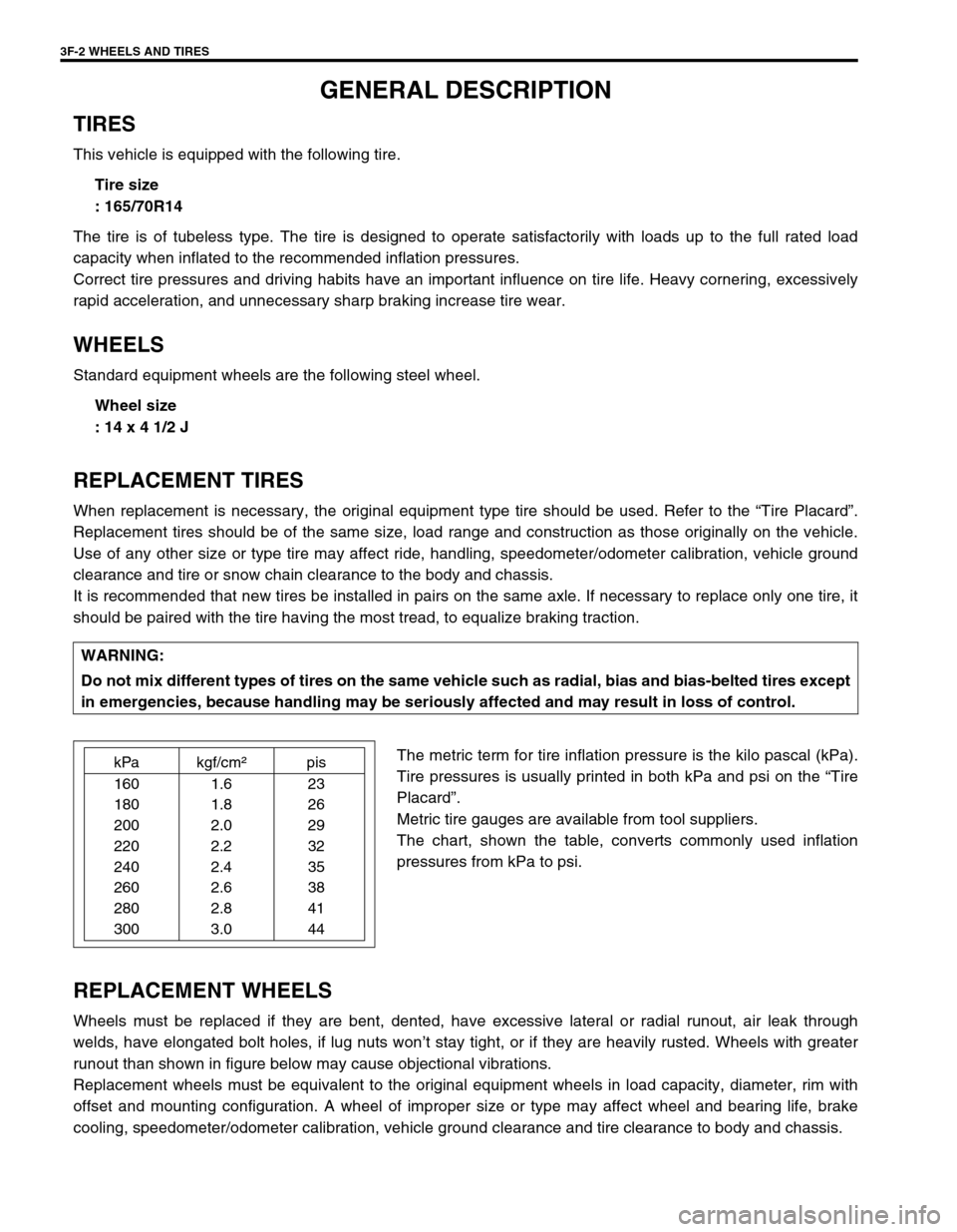
The metric term for tire inflation pressure is the kilo pascal (kPa).
Tire pressures is usually printed in both kPa and psi on the “Tire
Placard”.
Metric tire gauges are available from tool suppliers.
The chart, shown the table, converts commonly used inflation
pressures from kPa to psi.
REPLACEMENT WHEELS
Wheels must be replaced if they are bent, dented, have excessive lateral or radial runout, air leak through
welds, have elongated bolt holes, if lug nuts won’t stay tight, or if they are heavily rusted. Wheels with greater
runout than shown in figure below may cause objectional vibrations.
Replacement wheels must be equivalent to the original equipment wheels in load capacity, diameter, rim with
offset and mounting configuration. A wheel of improper size or type may affect wheel and bearing life, brake
cooling, speedometer/odometer calibration, vehicle ground clearance and tire clearance to body and chassis.WARNING:
Do not mix different types of tires on the same vehicle such as radial, bias and bias-belted tires except
in emergencies, because handling may be seriously affected and may result in loss of control.
kPa kgf/cm²pis
160 1.6 23
180 1.8 26
200 2.0 29
220 2.2 32
240 2.4 35
260 2.6 38
280 2.8 41
300 3.0 44
Page 250 of 698

WHEELS AND TIRES 3F-5
MAINTENANCE AND MINOR ADJUSTMENTS
WHEEL MAINTENANCE
Wheel repairs that use welding, heating, or peening are not approved. All damaged wheels should be replaced.
WHEEL ATTACHING STUDS
If a broken stud is found, see Section 3E (rear) or Section 3D (front) for Note and Replacement procedure.
MATCHED TIRES AND WHEELS
Tires and wheels are match mounted at the assembly plant.
This means that the radially stiffest part of the tire, or “high spot”,
is matched to the smallest radius or “low spot” of the wheel.
This is done to provide the smoothest possible ride.
The “high spot” of the tire is originally marked by paint dot (1) on
the outboard sidewall. This paint dot will eventually wash off the
tire.
The “ow spot” of the wheel is originally marked by paint dot (2) on
the wheel rim-flange. Properly assembled, the wheel rims’ paint
dot should be aligned with the tires’ paint dot as shown in left fig-
ure.
Whenever a tire is dismounted from its wheel, it should be
remounted so that the tire and wheel are matched. If the tire’s
paint dot cannot be located, a line should be scribed on the tire
and wheel before dismounting to assure that it is remounted in
the same position.
TIRE MAINTENANCE
TIRE PLACARD
The “Tire Placard” is located on the left door (right door for right-hand side steering vehicle) lock pillar and
should be referred to tire information.
The placard lists the maximum load, tire size and cold tire pressure where applicable.
NOTE:
Whether rim size and/or maximum load are listed or not depends on regulations of each country.
Page 253 of 698
3F-8 WHEELS AND TIRES
TIRE
MOUNTING AND DISMOUNTING
Use a tire changing machine to mount or dismount tires. Follow equipment manufacturer’s instructions. Do not
use hand tools or tire irons alone to change tires as they may damage tire beads or wheel rim.
Rim bead seats should be cleaned with a wire brush or coarse steel wool to remove lubricants, old rubber and
light rust. Before mounting or dismounting a tire, bead area should be well lubricated with approved tire lubri-
cant.
After mounting, inflate to specified pressure shown on tire placard so that beads are completely seated.
Install valve core and inflate to proper pressure.
REPAIR
There are many different materials and techniques on the market to repair tires. As not all of these work on all
types of tires, tire manufacturers have published detailed instructions on how and when to repair tires. These
instructions can be obtained from each tire manufacturer.WARNING:
Do not stand over tire when inflating. Bead may break when bead snaps over rim’s safety hump and
cause serious personal injury.
Do not exceed specified pressure when inflating. If specified pressure will not seat beads, deflate, re-
lubricate and reinflate.
Over inflation may cause bead to break and cause serious personal injury.
Page 261 of 698
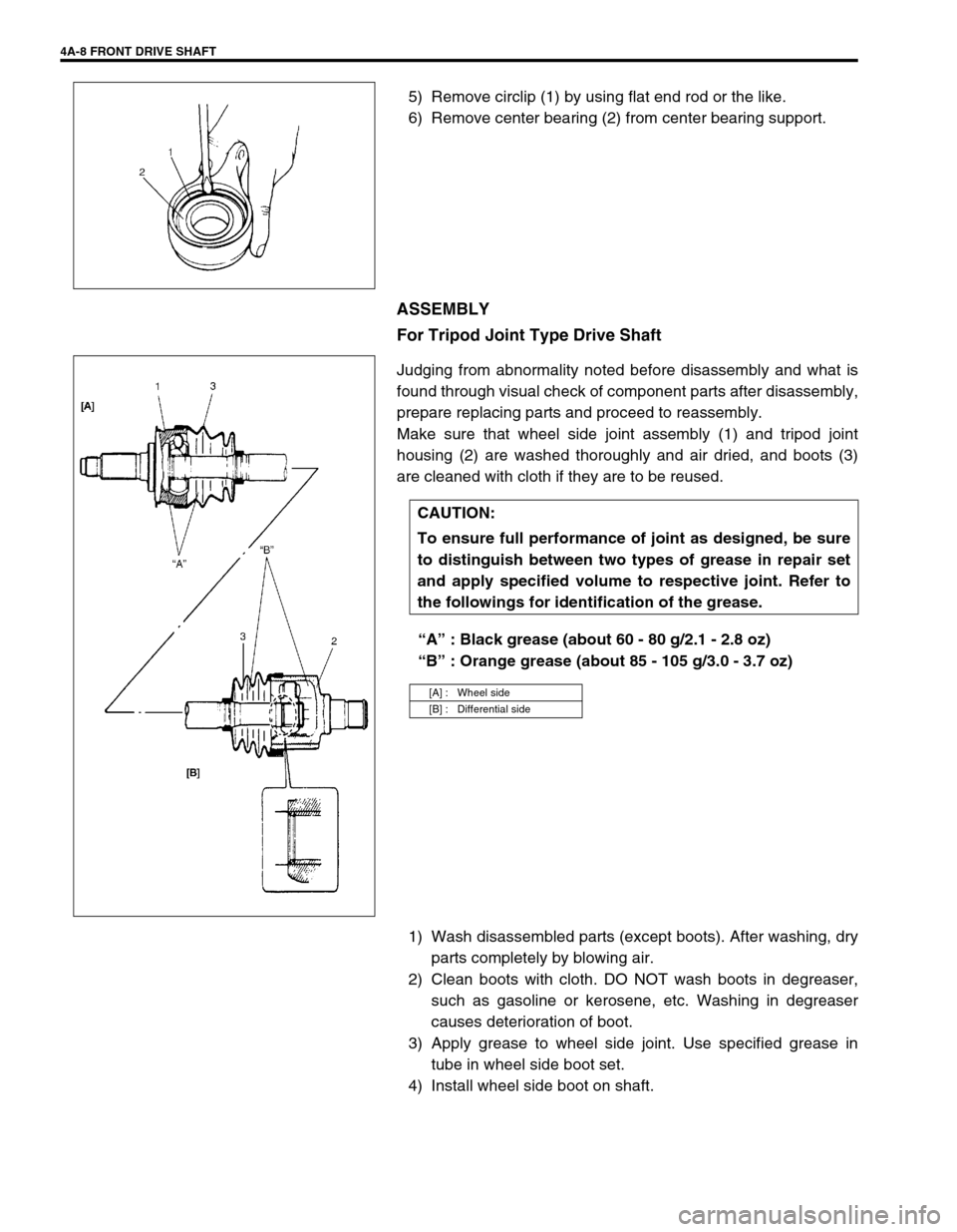
4A-8 FRONT DRIVE SHAFT
5) Remove circlip (1) by using flat end rod or the like.
6) Remove center bearing (2) from center bearing support.
ASSEMBLY
For Tripod Joint Type Drive Shaft
Judging from abnormality noted before disassembly and what is
found through visual check of component parts after disassembly,
prepare replacing parts and proceed to reassembly.
Make sure that wheel side joint assembly (1) and tripod joint
housing (2) are washed thoroughly and air dried, and boots (3)
are cleaned with cloth if they are to be reused.
“A” : Black grease (about 60 - 80 g/2.1 - 2.8 oz)
“B” : Orange grease (about 85 - 105 g/3.0 - 3.7 oz)
1) Wash disassembled parts (except boots). After washing, dry
parts completely by blowing air.
2) Clean boots with cloth. DO NOT wash boots in degreaser,
such as gasoline or kerosene, etc. Washing in degreaser
causes deterioration of boot.
3) Apply grease to wheel side joint. Use specified grease in
tube in wheel side boot set.
4) Install wheel side boot on shaft.
CAUTION:
To ensure full performance of joint as designed, be sure
to distinguish between two types of grease in repair set
and apply specified volume to respective joint. Refer to
the followings for identification of the grease.
[A] : Wheel side
[B] : Differential side