sensor SUZUKI SWIFT 2000 1.G RG413 Service Workshop Manual
[x] Cancel search | Manufacturer: SUZUKI, Model Year: 2000, Model line: SWIFT, Model: SUZUKI SWIFT 2000 1.GPages: 698, PDF Size: 16.01 MB
Page 587 of 698
6A1-86 ENGINE MECHANICAL (M13 ENGINE)
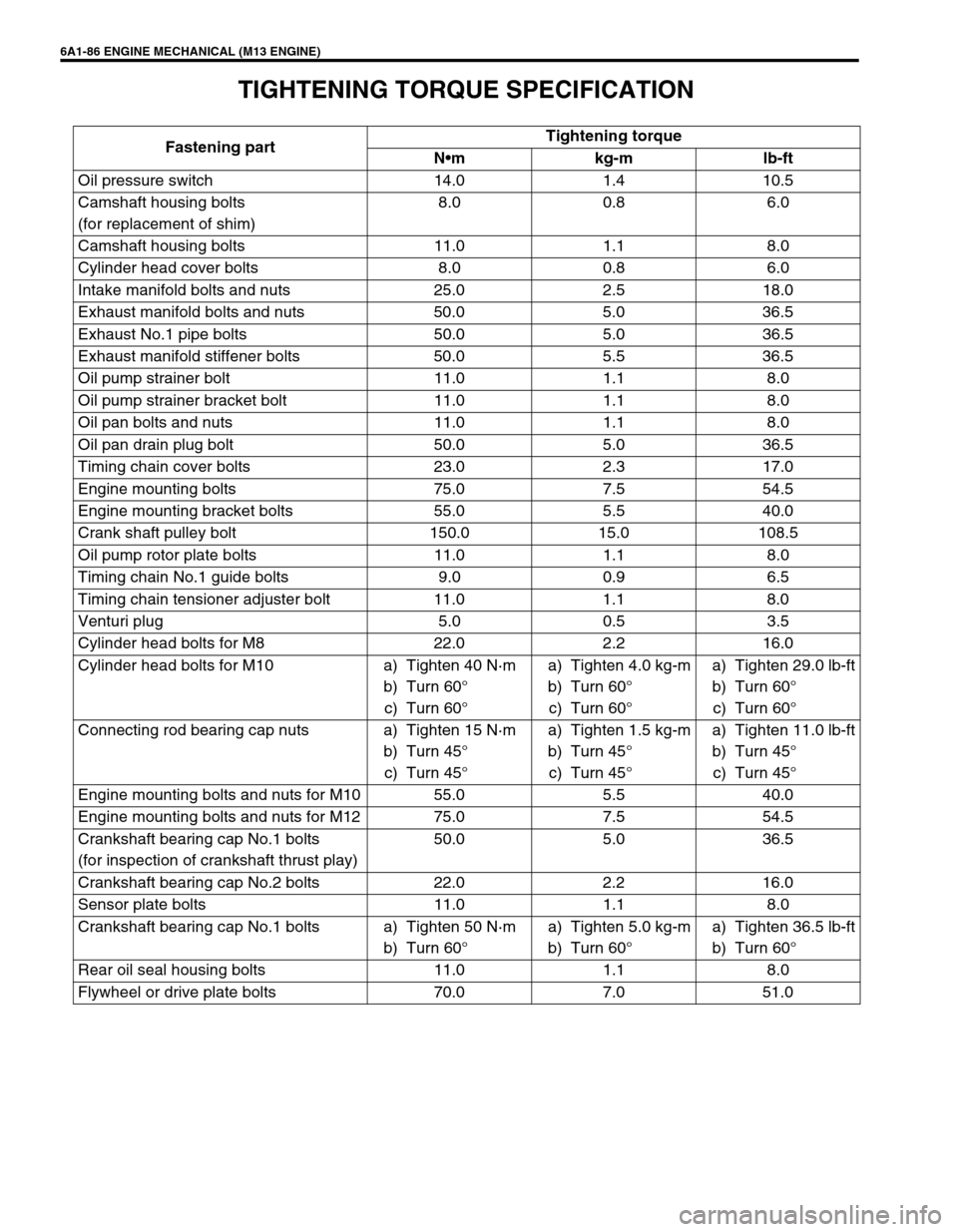
TIGHTENING TORQUE SPECIFICATION
Fastening partTightening torque
Nm kg-m lb-ft
Oil pressure switch 14.0 1.4 10.5
Camshaft housing bolts
(for replacement of shim)8.0 0.8 6.0
Camshaft housing bolts 11.0 1.1 8.0
Cylinder head cover bolts 8.0 0.8 6.0
Intake manifold bolts and nuts 25.0 2.5 18.0
Exhaust manifold bolts and nuts 50.0 5.0 36.5
Exhaust No.1 pipe bolts 50.0 5.0 36.5
Exhaust manifold stiffener bolts 50.0 5.5 36.5
Oil pump strainer bolt 11.0 1.1 8.0
Oil pump strainer bracket bolt 11.0 1.1 8.0
Oil pan bolts and nuts 11.0 1.1 8.0
Oil pan drain plug bolt 50.0 5.0 36.5
Timing chain cover bolts 23.0 2.3 17.0
Engine mounting bolts 75.0 7.5 54.5
Engine mounting bracket bolts 55.0 5.5 40.0
Crank shaft pulley bolt 150.0 15.0 108.5
Oil pump rotor plate bolts 11.0 1.1 8.0
Timing chain No.1 guide bolts 9.0 0.9 6.5
Timing chain tensioner adjuster bolt 11.0 1.1 8.0
Venturi plug 5.0 0.5 3.5
Cylinder head bolts for M8 22.0 2.2 16.0
Cylinder head bolts for M10 a) Tighten 40 N·m
b) Turn 60°
c) Turn 60°a) Tighten 4.0 kg-m
b) Turn 60°
c) Turn 60°a) Tighten 29.0 lb-ft
b) Turn 60°
c) Turn 60°
Connecting rod bearing cap nuts a) Tighten 15 N·m
b) Turn 45°
c) Turn 45°a) Tighten 1.5 kg-m
b) Turn 45°
c) Turn 45°a) Tighten 11.0 lb-ft
b) Turn 45°
c) Turn 45°
Engine mounting bolts and nuts for M10 55.0 5.5 40.0
Engine mounting bolts and nuts for M12 75.0 7.5 54.5
Crankshaft bearing cap No.1 bolts
(for inspection of crankshaft thrust play)50.0 5.0 36.5
Crankshaft bearing cap No.2 bolts 22.0 2.2 16.0
Sensor plate bolts 11.0 1.1 8.0
Crankshaft bearing cap No.1 bolts a) Tighten 50 N·m
b) Turn 60°a) Tighten 5.0 kg-m
b) Turn 60°a) Tighten 36.5 lb-ft
b) Turn 60°
Rear oil seal housing bolts 11.0 1.1 8.0
Flywheel or drive plate bolts 70.0 7.0 51.0
Page 590 of 698
ENGINE COOLING 6B-1
6B
SECTION 6B
ENGINE COOLING
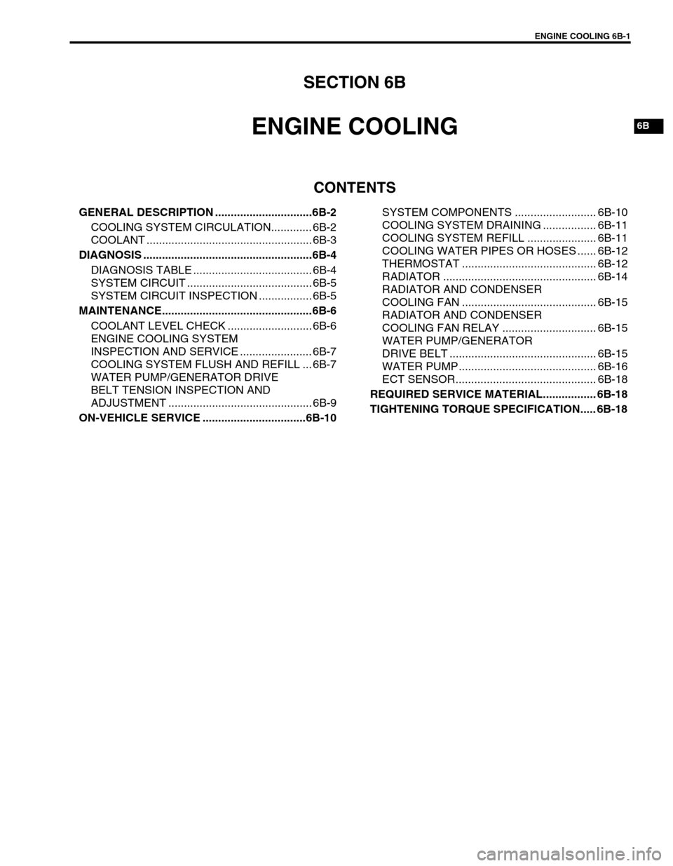
CONTENTS
GENERAL DESCRIPTION ...............................6B-2
COOLING SYSTEM CIRCULATION............. 6B-2
COOLANT ..................................................... 6B-3
DIAGNOSIS ......................................................6B-4
DIAGNOSIS TABLE ...................................... 6B-4
SYSTEM CIRCUIT ........................................ 6B-5
SYSTEM CIRCUIT INSPECTION ................. 6B-5
MAINTENANCE................................................6B-6
COOLANT LEVEL CHECK ........................... 6B-6
ENGINE COOLING SYSTEM
INSPECTION AND SERVICE ....................... 6B-7
COOLING SYSTEM FLUSH AND REFILL ... 6B-7
WATER PUMP/GENERATOR DRIVE
BELT TENSION INSPECTION AND
ADJUSTMENT .............................................. 6B-9
ON-VEHICLE SERVICE .................................6B-10SYSTEM COMPONENTS .......................... 6B-10
COOLING SYSTEM DRAINING ................. 6B-11
COOLING SYSTEM REFILL ...................... 6B-11
COOLING WATER PIPES OR HOSES ...... 6B-12
THERMOSTAT ........................................... 6B-12
RADIATOR ................................................. 6B-14
RADIATOR AND CONDENSER
COOLING FAN ........................................... 6B-15
RADIATOR AND CONDENSER
COOLING FAN RELAY .............................. 6B-15
WATER PUMP/GENERATOR
DRIVE BELT ............................................... 6B-15
WATER PUMP............................................ 6B-16
ECT SENSOR............................................. 6B-18
REQUIRED SERVICE MATERIAL................. 6B-18
TIGHTENING TORQUE SPECIFICATION..... 6B-18
Page 593 of 698
6B-4 ENGINE COOLING
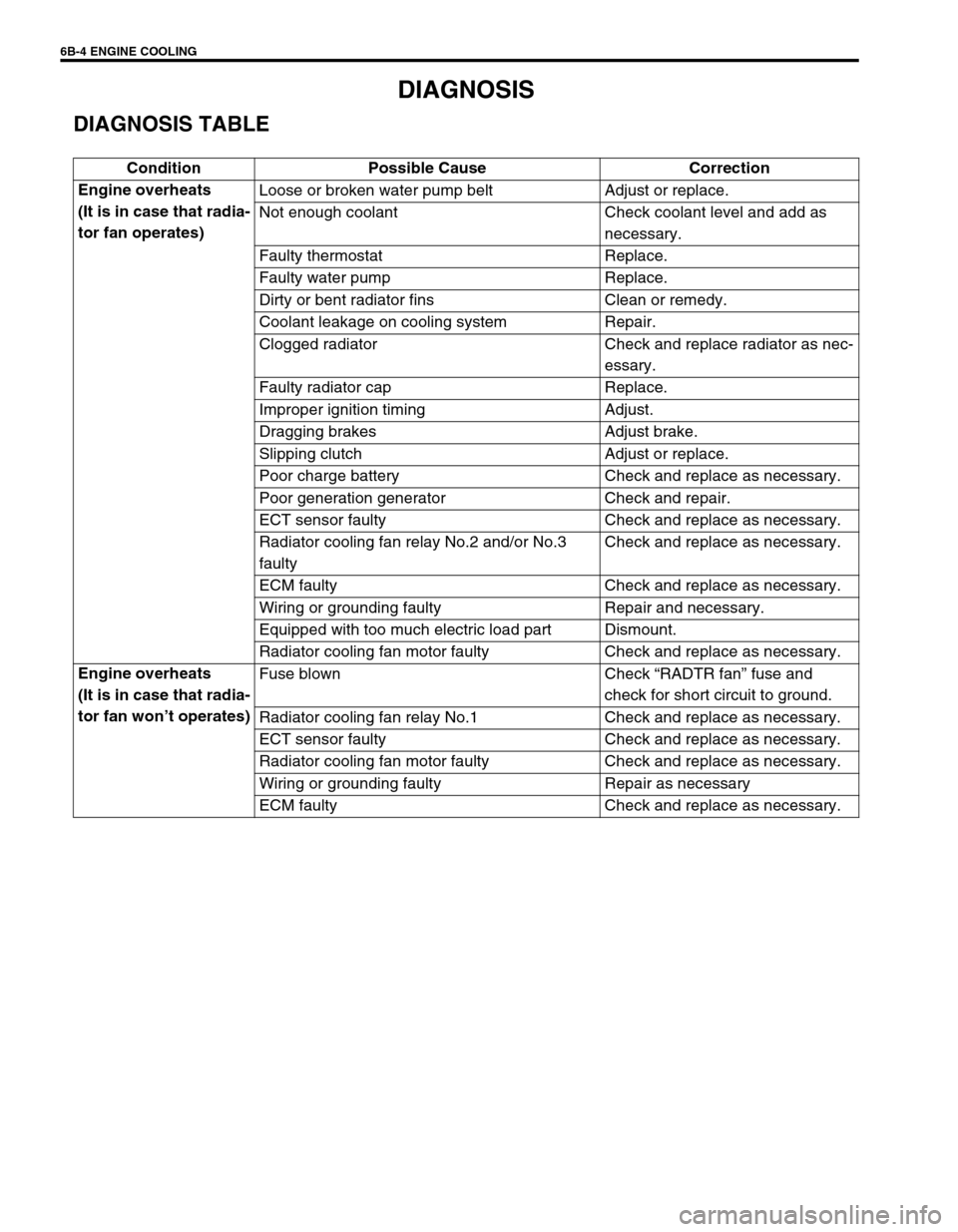
DIAGNOSIS
DIAGNOSIS TABLE
Condition Possible Cause Correction
Engine overheats
(It is in case that radia-
tor fan operates)Loose or broken water pump belt Adjust or replace.
Not enough coolant Check coolant level and add as
necessary.
Faulty thermostat Replace.
Faulty water pump Replace.
Dirty or bent radiator fins Clean or remedy.
Coolant leakage on cooling system Repair.
Clogged radiator Check and replace radiator as nec-
essary.
Faulty radiator cap Replace.
Improper ignition timing Adjust.
Dragging brakes Adjust brake.
Slipping clutch Adjust or replace.
Poor charge battery Check and replace as necessary.
Poor generation generator Check and repair.
ECT sensor faulty Check and replace as necessary.
Radiator cooling fan relay No.2 and/or No.3
faultyCheck and replace as necessary.
ECM faulty Check and replace as necessary.
Wiring or grounding faulty Repair and necessary.
Equipped with too much electric load part Dismount.
Radiator cooling fan motor faulty Check and replace as necessary.
Engine overheats
(It is in case that radia-
tor fan won’t operates)Fuse blown Check “RADTR fan” fuse and
check for short circuit to ground.
Radiator cooling fan relay No.1 Check and replace as necessary.
ECT sensor faulty Check and replace as necessary.
Radiator cooling fan motor faulty Check and replace as necessary.
Wiring or grounding faulty Repair as necessary
ECM faulty Check and replace as necessary.
Page 594 of 698
ENGINE COOLING 6B-5
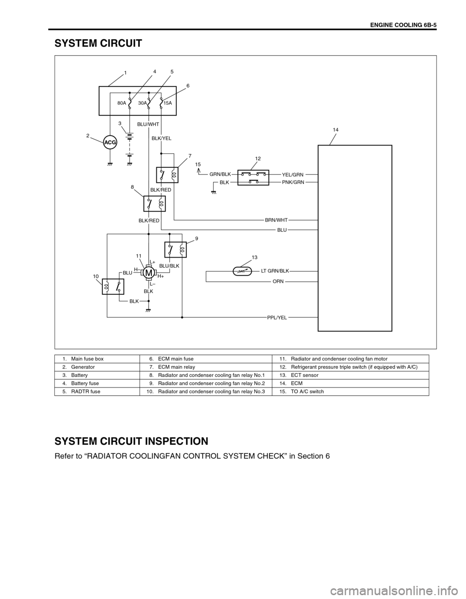
SYSTEM CIRCUIT
SYSTEM CIRCUIT INSPECTION
Refer to “RADIATOR COOLINGFAN CONTROL SYSTEM CHECK” in Section 6
1. Main fuse box 6. ECM main fuse 11. Radiator and condenser cooling fan motor
2. Generator 7. ECM main relay 12. Refrigerant pressure triple switch (if equipped with A/C)
3. Battery 8. Radiator and condenser cooling fan relay No.1 13. ECT sensor
4. Battery fuse 9. Radiator and condenser cooling fan relay No.2 14. ECM
5. RADTR fuse 10. Radiator and condenser cooling fan relay No.3 15. TO A/C switch
ACG
15A 30A
BLU/WHT
BLK/YEL
BLK
BLU
ORN
BLK
BLK
BLUH–
H+
L– L+
GRN/BLK
BLU/BLK
BRN/WHT
YEL/GRN
PNK/GRN
PPL/YEL
LT GRN/BLK
BLK/RED
BLK/RED 80A
145
6
2
3
7
8
9
11
10
13 15
12
14
Page 599 of 698
6B-10 ENGINE COOLING
ON-VEHICLE SERVICE
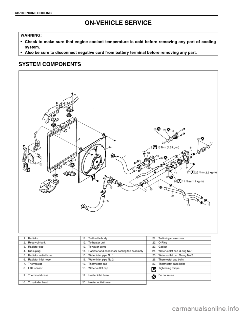
SYSTEM COMPONENTS
WARNING:
Check to make sure that engine coolant temperature is cold before removing any part of cooling
system.
Also be sure to disconnect negative cord from battery terminal before removing any part.
1. Radiator 11. To throttle body 21. To timing chain cover
2. Reservoir tank 12. To heater unit 22. O-Ring
3. Radiator cap 13. To water pump 23. Gasket
4. Drain plug 14. Radiator and condenser cooling fan assembly 24. Water outlet cap O-ring No.1
5. Radiator outlet hose 15. Water inlet pipe No.1 25. Water outlet cap O-ring No.2
6. Radiator inlet hose 16. Water inlet pipe No.2 26. Thermostat cap bolts
7. Thermostat 17. Thermostat cap 27. Thermostat case bolts
8. ECT sensor 18. Water outlet cap Tightening torque
9. Thermostat case 19. Heater inlet hose Do not reuse.
10. To cylinder head 20. Heater outlet hose
Page 607 of 698

6B-18 ENGINE COOLING
ECT SENSOR
Refer to “ECT SENSOR” in Section 6E1.
REQUIRED SERVICE MATERIAL
TIGHTENING TORQUE SPECIFICATION
MaterialRecommended SUZUKI product
(Part Number)Use
Ethylene glycol base
coolant (Anti-freeze/
Anti-corrosion coolant)—Additive to engine cooling system for improving
cooling efficiency and for protection against
rusting.
SealantSUZUKI BOND NO. 1207C
(99000-31150)To apply to mating surface of water pump
Fastening partTightening torque
Nm kg-m lb-ft
Generator adjusting bolt 23 2.3 17
Generator pivot bolt 50 5 36
Water pump bolt and Nuts 22 2.2 16
Page 617 of 698
6C-10 ENGINE FUEL
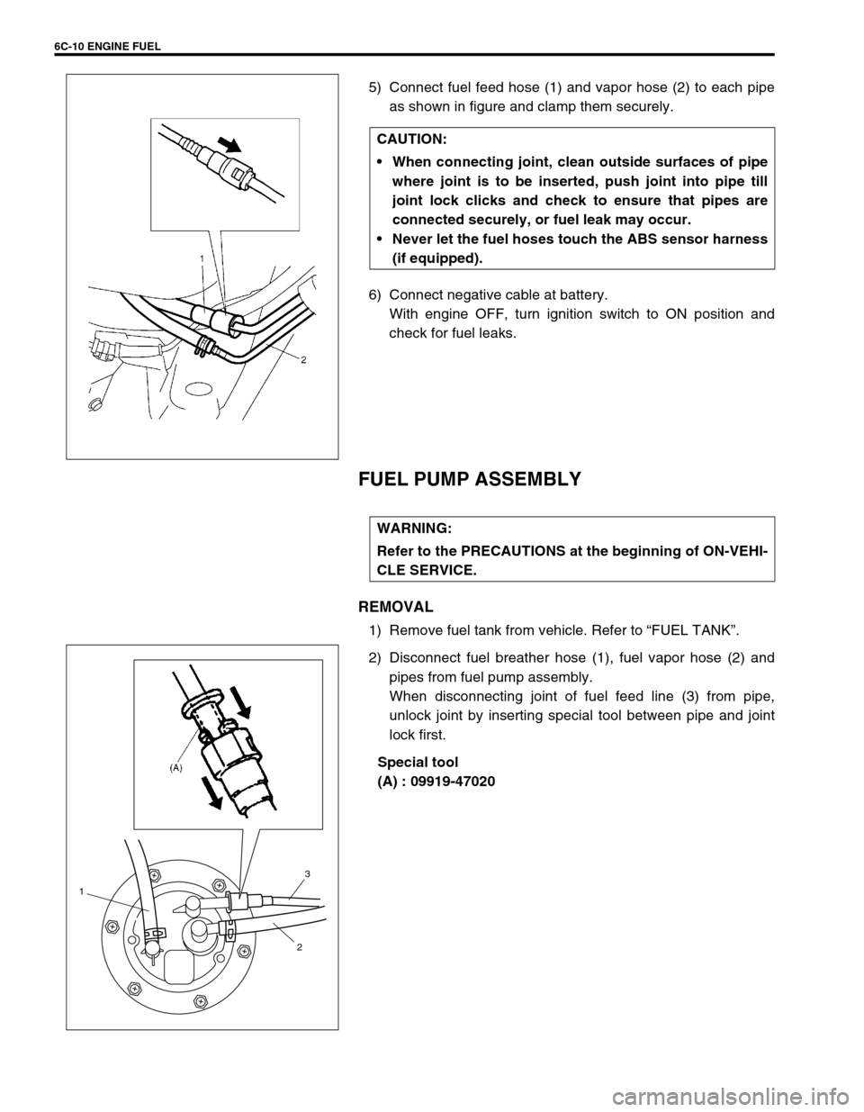
5) Connect fuel feed hose (1) and vapor hose (2) to each pipe
as shown in figure and clamp them securely.
6) Connect negative cable at battery.
With engine OFF, turn ignition switch to ON position and
check for fuel leaks.
FUEL PUMP ASSEMBLY
REMOVAL
1) Remove fuel tank from vehicle. Refer to “FUEL TANK”.
2) Disconnect fuel breather hose (1), fuel vapor hose (2) and
pipes from fuel pump assembly.
When disconnecting joint of fuel feed line (3) from pipe,
unlock joint by inserting special tool between pipe and joint
lock first.
Special tool
(A) : 09919-47020 CAUTION:
When connecting joint, clean outside surfaces of pipe
where joint is to be inserted, push joint into pipe till
joint lock clicks and check to ensure that pipes are
connected securely, or fuel leak may occur.
Never let the fuel hoses touch the ABS sensor harness
(if equipped).
WARNING:
Refer to the PRECAUTIONS at the beginning of ON-VEHI-
CLE SERVICE.
1
23
Page 619 of 698
6C-12 ENGINE FUEL
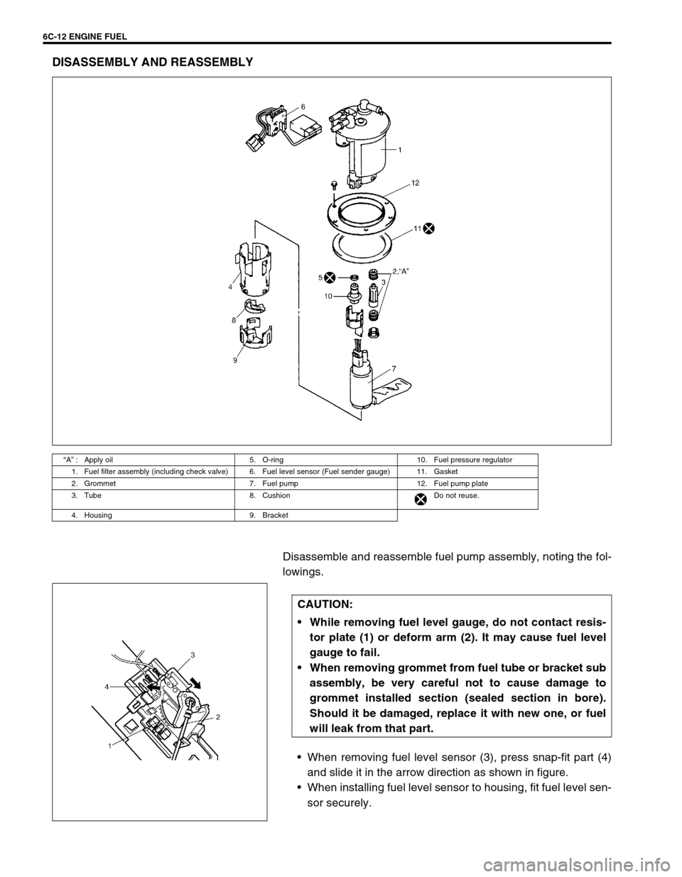
DISASSEMBLY AND REASSEMBLY
Disassemble and reassemble fuel pump assembly, noting the fol-
lowings.
When removing fuel level sensor (3), press snap-fit part (4)
and slide it in the arrow direction as shown in figure.
When installing fuel level sensor to housing, fit fuel level sen-
sor securely.
“A” : Apply oil 5. O-ring 10. Fuel pressure regulator
1. Fuel filter assembly (including check valve) 6. Fuel level sensor (Fuel sender gauge) 11. Gasket
2. Grommet 7. Fuel pump 12. Fuel pump plate
3. Tube 8. Cushion Do not reuse.
4. Housing 9. Bracket
CAUTION:
While removing fuel level gauge, do not contact resis-
tor plate (1) or deform arm (2). It may cause fuel level
gauge to fail.
When removing grommet from fuel tube or bracket sub
assembly, be very careful not to cause damage to
grommet installed section (sealed section in bore).
Should it be damaged, replace it with new one, or fuel
will leak from that part.
Page 622 of 698
ENGINE AND EMISSION CONTROL SYSTEM 6E1-1
6F1
6F2
6G
6H
6E1
7A
7A1
7B1
7C1
7D
7E
7F
8A
8B
8C
8D
8E
9
10
10A
10B
SECTION 6E1
ENGINE AND EMISSION CONTROL SYSTEM
CONTENTS
GENERAL DESCRIPTION ............................ 6E1-2
AIR INTAKE SYSTEM ............................... 6E1-5
FUEL DELIVERY SYSTEM ....................... 6E1-6
FUEL PUMP ........................................... 6E1-6
ELECTRONIC CONTROL SYSTEM .......... 6E1-7
ENGINE & EMISSION CONTROL
INPUT/OUTPUT TABLE ........................ 6E1-8
ECM INPUT/OUTPUT CIRCUIT
DIAGRAM............................................... 6E1-9
ECM TERMINAL ARRANGEMENT
TABLE .................................................. 6E1-13
ON-VEHICLE SERVICE .............................. 6E1-15
ACCELERATOR CABLE
ADJUSTMENT ..................................... 6E1-15
IDLE SPEED/IDLE AIR CONTROL
(IAC) DUTY INSPECTION ................... 6E1-15
IDLE MIXTURE INSPECTION /
ADJUSTMENT (VEHICLE WITHOUT
HEATED OXYGEN SENSOR) ............. 6E1-17
AIR INTAKE SYSTEM ............................. 6E1-18
THROTTLE BODY ............................... 6E1-18IDLE AIR CONTROL VALVE (IAC
VALVE) ................................................ 6E1-20
FUEL DELIVERY SYSTEM ..................... 6E1-21
FUEL PRESSURE INSPECTION ........ 6E1-21
FUEL PUMP WITH PRESSURE
REGULATOR ....................................... 6E1-22
FUEL INJECTOR ................................. 6E1-23
ELECTRONIC CONTROL SYSTEM ....... 6E1-27
ENGINE CONTROL MODULE
(ECM) ................................................... 6E1-27
MANIFOLD ABSOLUTE PRESSURE
SENSOR (MAP SENSOR)................... 6E1-27
THROTTLE POSITION SENSOR (TP
SENSOR) ............................................. 6E1-28
INTAKE AIR TEMPERATURE
SENSOR (IAT SENSOR) ..................... 6E1-29
ENGINE COOLANT TEMPERATURE
SENSOR (ECT SENSOR) ................... 6E1-30
HEATED OXYGEN SENSOR (HO2S-1
AND HO2S-2) ...................................... 6E1-31
CAMSHAFT POSITION SENSOR ....... 6E1-32 WARNING:
For vehicles equipped with Supplemental Restraint (Air Bag) System :
Service on and around the air bag system components or wiring must be performed only by an
authorized SUZUKI dealer. Refer to “Air Bag System Components and Wiring Location View” under
“General Description” in air bag system section in order to confirm whether you are performing ser-
vice on or near the air bag system components or wiring. Please observe all WARNINGS and “Ser-
vice Precautions” under “On-Vehicle Service” in air bag system section before performing service
on or around the air bag system components or wiring. Failure to follow WARNINGS could result in
unintentional activation of the system or could render the system inoperative. Either of these two
conditions may result in severe injury.
Technical service work must be started at least 90 seconds after the ignition switch is turned to the
“LOCK” position and the negative cable is disconnected from the battery. Otherwise, the system
may be activated by reserve energy in the Sensing and Diagnostic Module (SDM).
NOTE:
Whether the following system (parts) are used in the particular vehicle or not depends on vehicle
specifications. Be sure to bear this in mind when performing service work.
EGR valve
Heated oxygen sensor(s) or CO adjusting resistor
Three way catalytic converter
Immobilizer indicator lamp
Knock sensor
Page 623 of 698
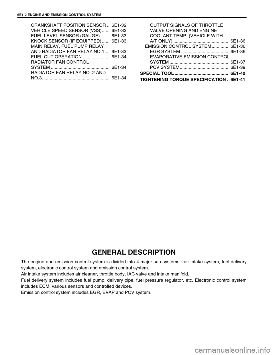
6E1-2 ENGINE AND EMISSION CONTROL SYSTEM
CRANKSHAFT POSITION SENSOR .. 6E1-32
VEHICLE SPEED SENSOR (VSS) ...... 6E1-33
FUEL LEVEL SENSOR (GAUGE) ....... 6E1-33
KNOCK SENSOR (IF EQUIPPED) ...... 6E1-33
MAIN RELAY, FUEL PUMP RELAY
AND RADIATOR FAN RELAY NO.1.... 6E1-33
FUEL CUT OPERATION ..................... 6E1-34
RADIATOR FAN CONTROL
SYSTEM .............................................. 6E1-34
RADIATOR FAN RELAY NO. 2 AND
NO.3 ..................................................... 6E1-34OUTPUT SIGNALS OF THROTTLE
VALVE OPENING AND ENGINE
COOLANT TEMP. (VEHICLE WITH
A/T ONLY) ........................................... 6E1-36
EMISSION CONTROL SYSTEM ............. 6E1-36
EGR SYSTEM ..................................... 6E1-36
EVAPORATIVE EMISSION CONTROL
SYSTEM .............................................. 6E1-37
PCV SYSTEM ...................................... 6E1-39
SPECIAL TOOL .......................................... 6E1-40
TIGHTENING TORQUE SPECIFICATION . 6E1-41
GENERAL DESCRIPTION
The engine and emission control system is divided into 4 major sub-systems : air intake system, fuel delivery
system, electronic control system and emission control system.
Air intake system includes air cleaner, throttle body, IAC valve and intake manifold.
Fuel delivery system includes fuel pump, delivery pipe, fuel pressure regulator, etc. Electronic control system
includes ECM, various sensors and controlled devices.
Emission control system includes EGR, EVAP and PCV system.