sensor SUZUKI SWIFT 2000 1.G RG413 Service Workshop Manual
[x] Cancel search | Manufacturer: SUZUKI, Model Year: 2000, Model line: SWIFT, Model: SUZUKI SWIFT 2000 1.GPages: 698, PDF Size: 16.01 MB
Page 641 of 698

6E1-20 ENGINE AND EMISSION CONTROL SYSTEM
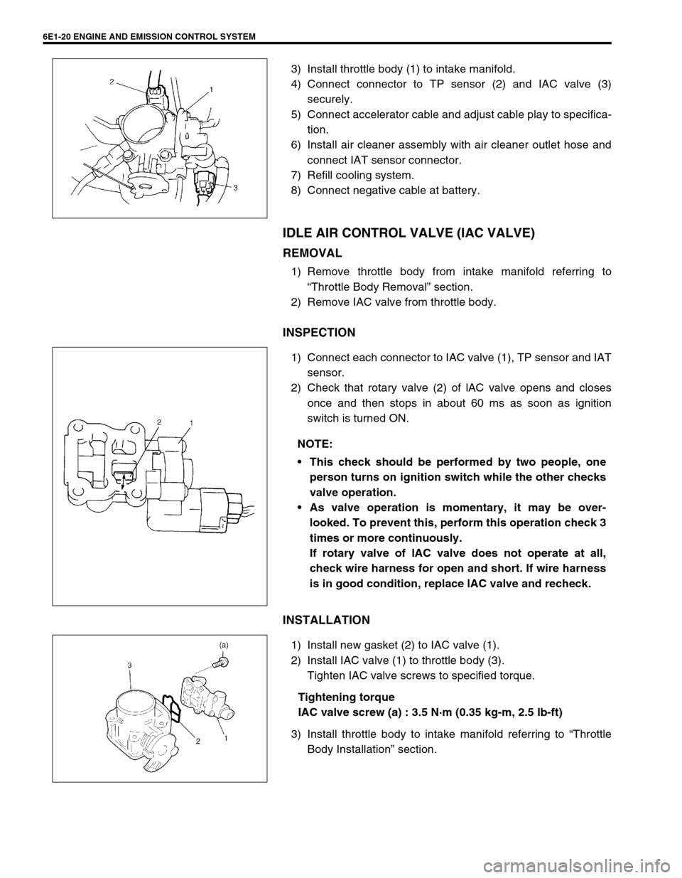
3) Install throttle body (1) to intake manifold.
4) Connect connector to TP sensor (2) and IAC valve (3)
securely.
5) Connect accelerator cable and adjust cable play to specifica-
tion.
6) Install air cleaner assembly with air cleaner outlet hose and
connect IAT sensor connector.
7) Refill cooling system.
8) Connect negative cable at battery.
IDLE AIR CONTROL VALVE (IAC VALVE)
REMOVAL
1) Remove throttle body from intake manifold referring to
“Throttle Body Removal” section.
2) Remove IAC valve from throttle body.
INSPECTION
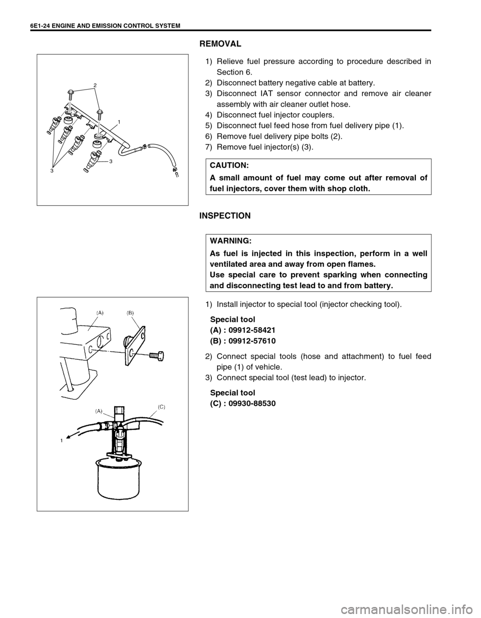
1) Connect each connector to IAC valve (1), TP sensor and IAT
sensor.
2) Check that rotary valve (2) of lAC valve opens and closes
once and then stops in about 60 ms as soon as ignition
switch is turned ON.
INSTALLATION
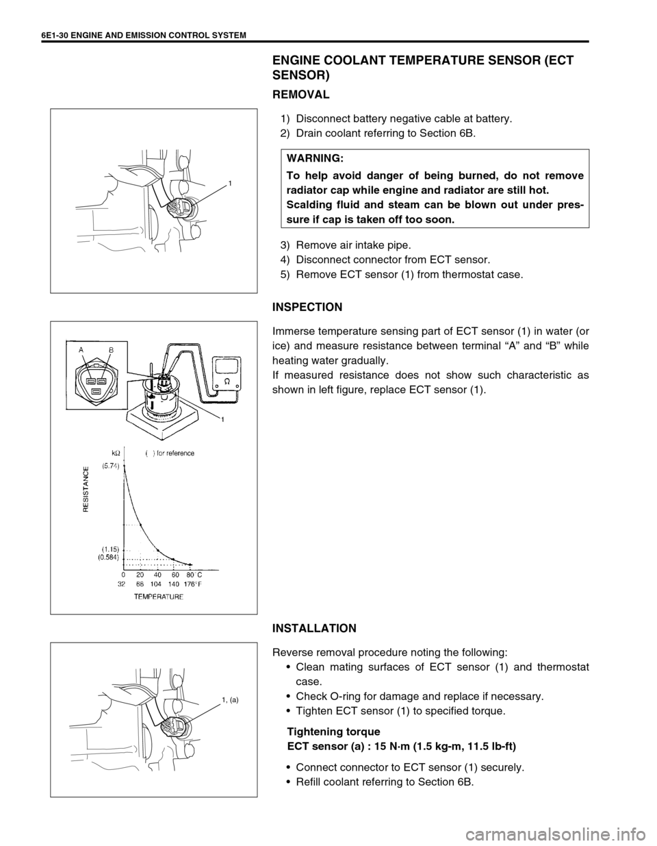
1) Install new gasket (2) to IAC valve (1).
2) Install IAC valve (1) to throttle body (3).
Tighten IAC valve screws to specified torque.
Tightening torque
IAC valve screw (a) : 3.5 N·m (0.35 kg-m, 2.5 lb-ft)
3) Install throttle body to intake manifold referring to “Throttle
Body Installation” section.
NOTE:
This check should be performed by two people, one
person turns on ignition switch while the other checks
valve operation.
As valve operation is momentary, it may be over-
looked. To prevent this, perform this operation check 3
times or more continuously.
If rotary valve of lAC valve does not operate at all,
check wire harness for open and short. If wire harness
is in good condition, replace lAC valve and recheck.
Page 645 of 698

6E1-24 ENGINE AND EMISSION CONTROL SYSTEM
REMOVAL
1) Relieve fuel pressure according to procedure described in
Section 6.
2) Disconnect battery negative cable at battery.
3) Disconnect IAT sensor connector and remove air cleaner
assembly with air cleaner outlet hose.
4) Disconnect fuel injector couplers.
5) Disconnect fuel feed hose from fuel delivery pipe (1).
6) Remove fuel delivery pipe bolts (2).
7) Remove fuel injector(s) (3).
INSPECTION
1) Install injector to special tool (injector checking tool).
Special tool
(A) : 09912-58421
(B) : 09912-57610
2) Connect special tools (hose and attachment) to fuel feed
pipe (1) of vehicle.
3) Connect special tool (test lead) to injector.
Special tool
(C) : 09930-88530 CAUTION:
A small amount of fuel may come out after removal of
fuel injectors, cover them with shop cloth.
2
1
3
3
WARNING:
As fuel is injected in this inspection, perform in a well
ventilated area and away from open flames.
Use special care to prevent sparking when connecting
and disconnecting test lead to and from battery.
Page 648 of 698

ENGINE AND EMISSION CONTROL SYSTEM 6E1-27
ELECTRONIC CONTROL SYSTEM
ENGINE CONTROL MODULE (ECM)
REMOVAL
1) Disconnect battery negative cable at battery.
2) Disable air bag system, referring to “Disabling The Air Bag
System” in Section 10B if equipped.
3) Disconnect ECM (1) and TCM (2) (if equipped) connectors.
4) Remove bolt and nuts, remove ECM and TCM (if equipped).
INSTALLATION
Reverse removal procedure noting the following:
Connect connectors to ECM and TCM (if equipped) securely.
MANIFOLD ABSOLUTE PRESSURE SENSOR (MAP
SENSOR)
INSPECTION
Check MAP sensor referring to “MAP Sensor Individual Check” in
DTC P0105 (No.11) Flow Table. If malfunction is found, replace.CAUTION:
As ECM consists of precision parts, be careful not to
expose it to excessive shock.
2
1
Page 649 of 698

6E1-28 ENGINE AND EMISSION CONTROL SYSTEM
THROTTLE POSITION SENSOR (TP SENSOR)
INSPECTION
1) Disconnect negative cable at battery and connector from IAT
sensor.
2) Remove air cleaner assembly with air cleaner outlet hose
and disconnect TP sensor connector.
3) Using ohmmeter, check resistance between terminals under
each condition given in table below.
If check result is not satisfactory, replace TP sensor.
TP sensor resistance
4) Connect TP sensor connector securely.
5) Connect negative cable to battery.
REMOVAL
1) Disconnect battery negative cable at battery.
2) Remove throttle body from intake manifold referring to
“Throttle Body Removal” in this section.
3) Remove TP sensor from throttle body.
INSTALLATION
1) Install TP sensor (1) to throttle body.
Fit TP sensor to throttle body in such way that its holes (3)
are a little away from TP sensor screw holes (2) as shown in
left figure and turn TP sensor clockwise so that those holes
align (4).
Tightening torque
TP sensor screw (a) : 2.5 N·m (0.25 kg-m, 1.8 lb-ft)
2) Connect connector to TP sensor securely.
3) Connect battery negative cable to battery.TERMINALS RESISTANCE
Between 1 and
3 terminals4.0 – 6.0 k
Ω
Between 2 and
3 terminals20
Ω – 6.0 k
Ω, varying according to throt-
tle valve opening.
NOTE:
There should be more than 2 k
Ω resistance difference
between when throttle valve is at idle position and when
it is fully open.
1. Reference voltage terminal
2. Output voltage terminal
3. Ground terminal
Page 650 of 698

ENGINE AND EMISSION CONTROL SYSTEM 6E1-29
INTAKE AIR TEMPERATURE SENSOR (IAT SENSOR)
REMOVAL
1) Disconnect battery negative cable at battery.
2) Disconnect coupler (1) from IAT sensor.
3) Remove IAT sensor from air cleaner case (2).
INSPECTION
Immerse temperature sensing part of IAT sensor in water (or ice)
and measure resistance between sensor terminals while heating
water gradually.
If measured resistance does not show such characteristic as
shown in left figure, replace IAT sensor.
INSTALLATION
Reverse removal procedure noting the following.
Clean mating surfaces of IAT sensor and air cleaner case.
Connect IAT sensor connector (1) securely.
1
2
1
Page 651 of 698

6E1-30 ENGINE AND EMISSION CONTROL SYSTEM
ENGINE COOLANT TEMPERATURE SENSOR (ECT
SENSOR)
REMOVAL
1) Disconnect battery negative cable at battery.
2) Drain coolant referring to Section 6B.
3) Remove air intake pipe.
4) Disconnect connector from ECT sensor.
5) Remove ECT sensor (1) from thermostat case.
INSPECTION
Immerse temperature sensing part of ECT sensor (1) in water (or
ice) and measure resistance between terminal “A” and “B” while
heating water gradually.
If measured resistance does not show such characteristic as
shown in left figure, replace ECT sensor (1).
INSTALLATION
Reverse removal procedure noting the following:
Clean mating surfaces of ECT sensor (1) and thermostat
case.
Check O-ring for damage and replace if necessary.
Tighten ECT sensor (1) to specified torque.
Tightening torque
ECT sensor (a) : 15 N·m (1.5 kg-m, 11.5 lb-ft)
Connect connector to ECT sensor (1) securely.
Refill coolant referring to Section 6B. WARNING:
To help avoid danger of being burned, do not remove
radiator cap while engine and radiator are still hot.
Scalding fluid and steam can be blown out under pres-
sure if cap is taken off too soon.
1
1, (a)
Page 652 of 698

ENGINE AND EMISSION CONTROL SYSTEM 6E1-31
HEATED OXYGEN SENSOR (HO2S-1 AND HO2S-2)
OXYGEN SENSOR HEATER INSPECTION
1) Disconnect sensor connector.
2) Using ohmmeter, measure resistance between terminals
“V
B” and “GND” of sensor connector.
If found faulty, replace oxygen sensor.
Resistance of oxygen sensor heater
HO2S-1 : 5.0 – 6.4
Ω at 20°C (68°F)
HO2S-2 : 11.7 – 14.3
Ω at 20°C (68°F)
3) Connect sensor connector securely.
REMOVAL
1) Disconnect negative cable at battery.
2) For HO2S-1, disconnect connector of heated oxygen sensor
and release its wire harness from clamps, then remove front
bumper and heat insulator panel.
3) For HO2S-2, disconnect connector of heated oxygen sensor
and release its wire harness from clamp and hoist vehicle.
4) Remove heated oxygen sensor (1) from exhaust manifold or
exhaust pipe.
INSTALLATION
Reverse removal procedure noting the following.
Tighten heated oxygen sensor (1) to specified torque.
Tightening torque
Heated oxygen sensor (a) : 45 N·m (4.5 kg-m, 32.5 lb-ft)
Connect connector of heated oxygen sensor (1) and clamp
wire harness securely.
After installing heated oxygen sensor (1), start engine and
check that no exhaust gas leakage exists. NOTE:
Temperature of sensor affects resistance value largely.
Make sure that sensor heater is at correct temperature.
1. Viewed from terminal side
WARNING:
To avoid danger of being burned, do not touch exhaust
system when system is hot. Oxygen sensor removal
should be performed when system is cool.
[A] : HO2S-1
[B] : HO2S-2
Page 653 of 698

6E1-32 ENGINE AND EMISSION CONTROL SYSTEM
CAMSHAFT POSITION SENSOR
INSPECTION
Check camshaft position sensor referring to DTC P0340 (No.15)
Diag. Flow Table in Section 6. If malfunction is found, replace.
REMOVAL
1) Disconnect negative cable at battery.
2) Disconnect connector from camshaft position sensor.
3) Remove camshaft position sensor from cylinder head.
INSTALLATION
1) Check that O-ring is free from damage.
2) Check that camshaft position sensor and signal rotor teeth
are free from any metal particles and damage.
3) Install camshaft position sensor to cylinder head.
Tightening torque
Camshaft position sensor bolt
(a) : 10 N·m (1.0 kg-m, 7.5 lb-ft)
4) Connect connector to it securely.
5) Connect negative cable to battery.
CRANKSHAFT POSITION SENSOR
INSPECTION
Check crankshaft position sensor referring to step 1 and 2 of DTC
P0335 (No.23) Flow Table. If malfunction is found, replace.
REMOVAL
1) Disconnect negative cable at battery.
2) Remove generator drive belt, loosen pivot bolt and move
generator outward.
3) Disconnect connector from crankshaft position sensor.
4) Remove crankshaft position sensor (1) from cylinder block.
INSTALLATION
1) Check to make sure that crankshaft position sensor and pul-
ley teeth are free from any metal particles and damage.
2) Install crankshaft position sensor to cylinder block.
3) Connect connector to it securely.
4) Adjust generator belt tension, refer to Section 6B.
5) Connect negative cable to battery.
Page 654 of 698

ENGINE AND EMISSION CONTROL SYSTEM 6E1-33
VEHICLE SPEED SENSOR (VSS)
INSPECTION
Check vehicle speed sensor referring to step 3 of DTC P0500
(No.16) Flow Table. If malfunction is found, replace.
REMOVAL/INSTALLATION
Refer to Section 7A.
FUEL LEVEL SENSOR (GAUGE)
INSPECTION
Refer to Section 8.
REMOVAL/INSTALLATION
Refer to Section 6C.
KNOCK SENSOR (IF EQUIPPED)
INSPECTION
Check knock sensor referring to DTC P0325 (No.17) Flow Table.
If malfunction is found, replace.
REMOVAL/INSTALLATION
Refer to Section 6A.
MAIN RELAY, FUEL PUMP RELAY AND RADIATOR
FAN RELAY NO.1
INSPECTION
1) Disconnect negative cable at battery.
2) Remove main relay (1), fuel pump relay (2) and radiator fan
control relay No.1 (3) from vehicle.
3) Check that there is no continuity between terminal “C” and
“D”. If there is continuity, replace relay.
4) Connect battery positive (+) terminal to terminal “B” of relay.
Connect battery negative (–) terminal “A” of relay.
Check continuity between terminal “C” and “D”.
If there is no continuity when relay is connected to the bat-
tery, replace relay.
“D” “B”“A”“C”
3
1
2
Page 655 of 698

6E1-34 ENGINE AND EMISSION CONTROL SYSTEM
FUEL CUT OPERATION
INSPECTION
1) Warm up engine to normal operating temperature.
2) While listening to sound of injector (1) by using sound scope
(2) or such, increase engine speed to higher than 3,000 r/
min.
3) Check to make sure that sound to indicate operation of injec-
tor stops when throttle valve is closed instantly and it is
heard again when engine speed is reduced to less than
about 2,000 r/min.
RADIATOR FAN CONTROL SYSTEM
SYSTEM INSPECTION
Check system for operation referring to Flow Table B-7 in Section
6.
If radiator fan fails to operate properly, check relay, radiator fan
and electrical circuit.
RADIATOR FAN RELAY NO. 2 AND NO.3
INSPECTION
1) Disconnect negative cable at battery.
2) Remove relay(s) from connector(s).NOTE:
Before inspection, check to make sure that gear shift
lever is in neutral position (with A/T model, selector lever
in “P” range), A/C is OFF and that parking brake lever is
pulled all the way up.
WARNING:
Keep hands, tools, and clothing away from engine cool-
ing fan to help prevent personal injury. This fan is electric
and can come on whether or not the engine is running.
The fan can start automatically in response to the ECT
sensor with the ignition switch in the “ON” position.
1. Radiator fan relay No. 2
2. Radiator fan relay No. 3
1
2