ABS SUZUKI SWIFT 2000 1.G RG413 Service User Guide
[x] Cancel search | Manufacturer: SUZUKI, Model Year: 2000, Model line: SWIFT, Model: SUZUKI SWIFT 2000 1.GPages: 698, PDF Size: 16.01 MB
Page 205 of 698
3D-12 FRONT SUSPENSION
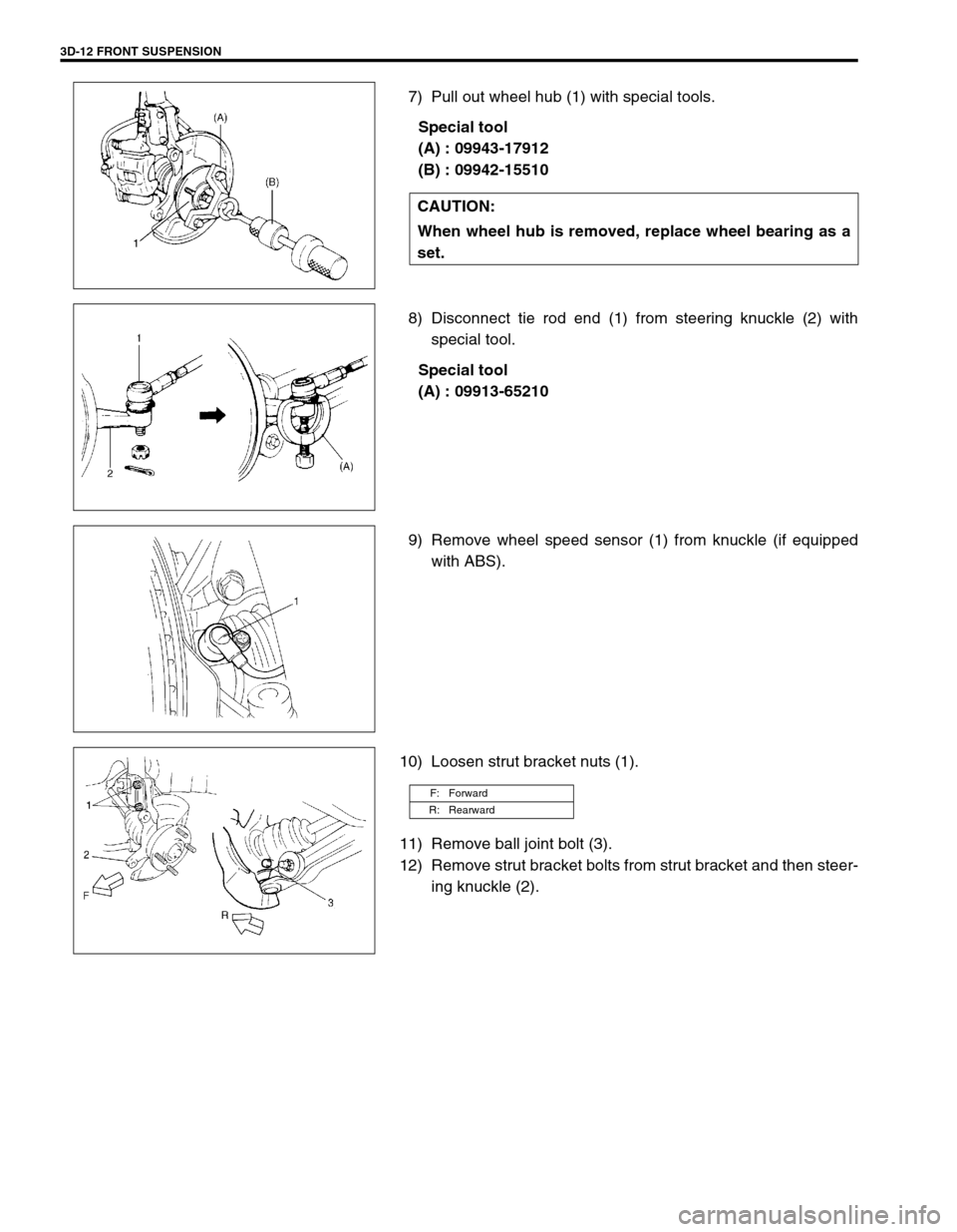
7) Pull out wheel hub (1) with special tools.
Special tool
(A) : 09943-17912
(B) : 09942-15510
8) Disconnect tie rod end (1) from steering knuckle (2) with
special tool.
Special tool
(A) : 09913-65210
9) Remove wheel speed sensor (1) from knuckle (if equipped
with ABS).
10) Loosen strut bracket nuts (1).
11) Remove ball joint bolt (3).
12) Remove strut bracket bolts from strut bracket and then steer-
ing knuckle (2). CAUTION:
When wheel hub is removed, replace wheel bearing as a
set.
F: Forward
R: Rearward
Page 208 of 698
FRONT SUSPENSION 3D-15
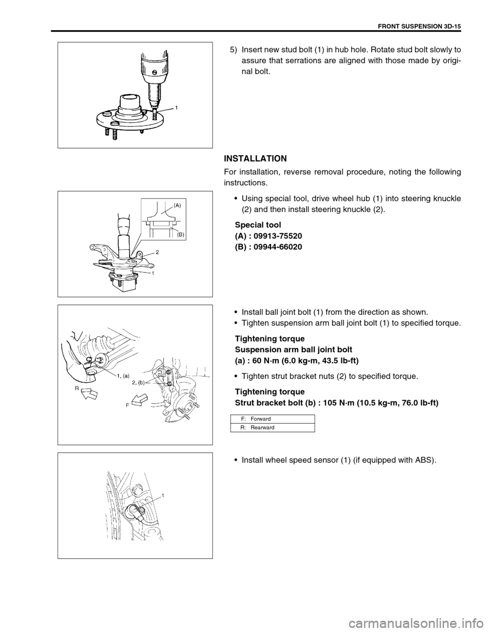
5) Insert new stud bolt (1) in hub hole. Rotate stud bolt slowly to
assure that serrations are aligned with those made by origi-
nal bolt.
INSTALLATION
For installation, reverse removal procedure, noting the following
instructions.
Using special tool, drive wheel hub (1) into steering knuckle
(2) and then install steering knuckle (2).
Special tool
(A) : 09913-75520
(B) : 09944-66020
Install ball joint bolt (1) from the direction as shown.
Tighten suspension arm ball joint bolt (1) to specified torque.
Tightening torque
Suspension arm ball joint bolt
(a) : 60 N·m (6.0 kg-m, 43.5 lb-ft)
Tighten strut bracket nuts (2) to specified torque.
Tightening torque
Strut bracket bolt (b) : 105 N·m (10.5 kg-m, 76.0 lb-ft)
Install wheel speed sensor (1) (if equipped with ABS).
F: Forward
R: Rearward
Page 214 of 698
REAR SUSPENSION 3E-1
6F1
6F2
6G
1A
6K
7A
7A1
7B1
7C1
3E
8A
8B
8C
8D
8E
9
10
10A
10B
SECTION 3E
REAR SUSPENSION
CONTENTS
GENERAL DESCRIPTION .............................. 3E-2
DIAGNOSIS ..................................................... 3E-4
REAR SHOCK ABSORBER CHECK ........... 3E-4
TRAILING ARM, LATERAL ROD, REAR
AXLE, PEAR AXLE HOUSING AND COIL
SPRING CHECK .......................................... 3E-4
BUMP STOPPER/SPRING UPPER SEAT
CHECK ......................................................... 3E-5
REAR SUSPENSION FASTENERS ............ 3E-5
WHEEL DISC, NUT AND BEARING
CHECK ......................................................... 3E-5
ON-VEHICLE SERVICE .................................. 3E-6
LATERAL ROD ............................................ 3E-6
REAR SHOCK ABSORBER......................... 3E-7
COIL SPRING .............................................. 3E-7BUMP STOPPER ...................................... 3E-10
SPRING UPPER SEAT ............................. 3E-11
TRAILING ARM ......................................... 3E-11
REAR AXLE (2WD VEHICLE) ................... 3E-14
WHEEL BEARING AND WHEEL STUD
(2WD VEHICLE) ........................................ 3E-19
REAR AXLE SHAFT AND WHEEL
BEARING (4WD VEHICLE) ....................... 3E-21
REAR AXLE SHAFT OIL SEAL (4WD
VEHICLE) .................................................. 3E-25
REAR AXLE HOUSING (4WD
VEHICLE) .................................................. 3E-26
REQUIRED SERVICE MATERIAL................ 3E-32
SPECIAL TOOL ............................................ 3E-32
NOTE:
All suspension fasteners are an important attaching part in that it could affect the performance of
vital parts and systems, and/or could result in major repair expense. They must be replaced with
one of the same part number or with an equivalent part if replacement becomes necessary. Do not
use a replacement part of lesser quality or substitute design. Torque values must be used as speci-
fied during reassembly to assure proper retention of this part.
Never attempt to heat, quench or straighten any front suspension part. Replace it with a new part, or
damage to the part may result.
Page 215 of 698
3E-2 REAR SUSPENSION
GENERAL DESCRIPTION
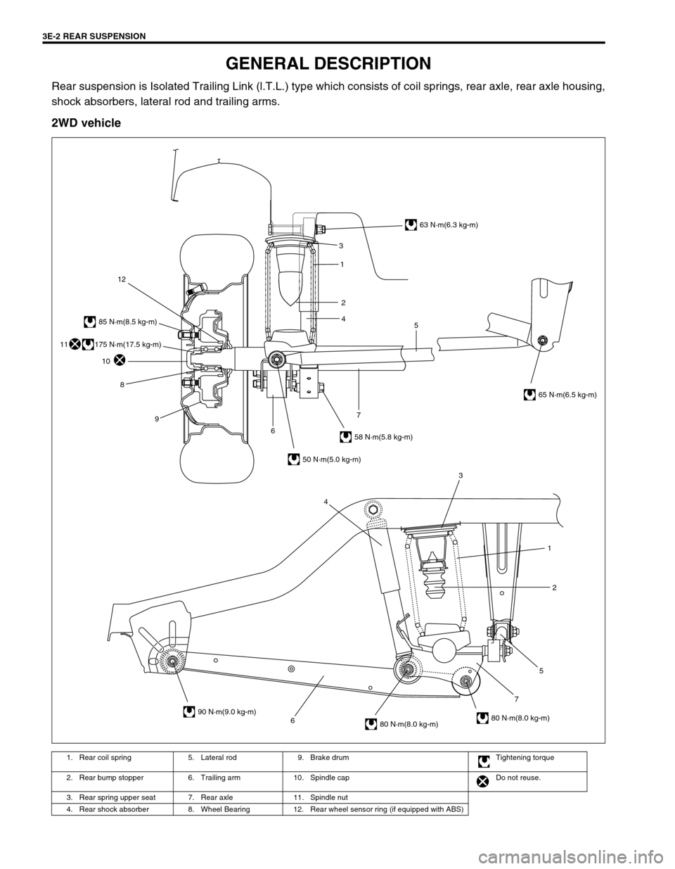
Rear suspension is Isolated Trailing Link (l.T.L.) type which consists of coil springs, rear axle, rear axle housing,
shock absorbers, lateral rod and trailing arms.
2WD vehicle
1. Rear coil spring 5. Lateral rod 9. Brake drum Tightening torque
2. Rear bump stopper 6. Trailing arm 10. Spindle cap Do not reuse.
3. Rear spring upper seat 7. Rear axle 11. Spindle nut
4. Rear shock absorber 8. Wheel Bearing 12. Rear wheel sensor ring (if equipped with ABS)
6752 1 3
4
3
5 1
2
4
63 N·m(6.3 kg-m)
65 N·m(6.5 kg-m)
58 N·m(5.8 kg-m)
50 N·m(5.0 kg-m)
90 N·m(9.0 kg-m)
80 N·m(8.0 kg-m)80 N·m(8.0 kg-m)
85 N·m(8.5 kg-m)
12
10
8
9
67
175 N·m(17.5 kg-m)11
Page 216 of 698
REAR SUSPENSION 3E-3
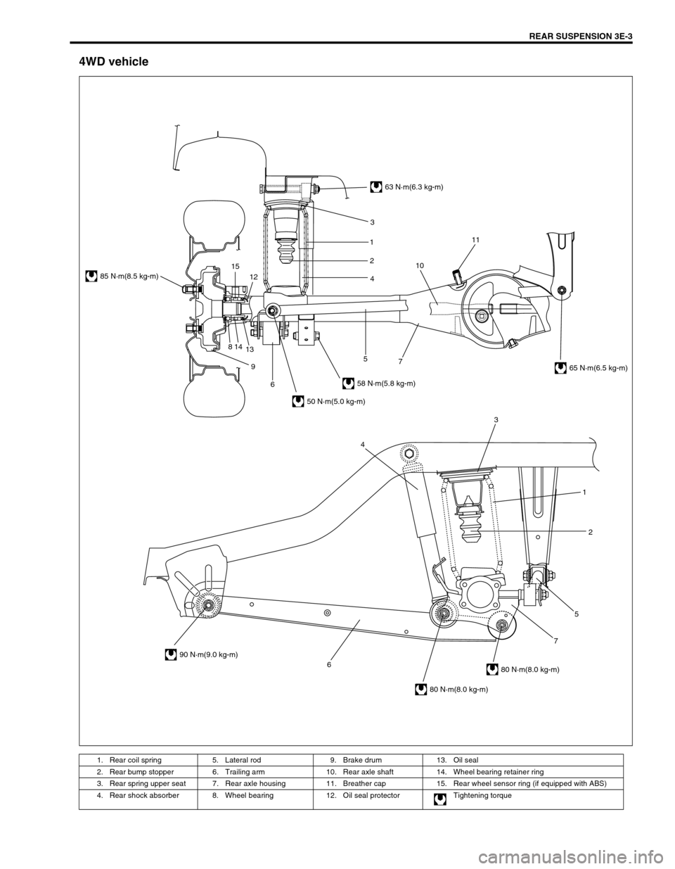
4WD vehicle
1. Rear coil spring 5. Lateral rod 9. Brake drum 13. Oil seal
2. Rear bump stopper 6. Trailing arm 10. Rear axle shaft 14. Wheel bearing retainer ring
3. Rear spring upper seat 7. Rear axle housing 11. Breather cap 15. Rear wheel sensor ring (if equipped with ABS)
4. Rear shock absorber 8. Wheel bearing 12. Oil seal protector Tightening torque
6752 1 3
4
63 N·m(6.3 kg-m)
58 N·m(5.8 kg-m)
50 N·m(5.0 kg-m)
85 N·m(8.5 kg-m)
90 N·m(9.0 kg-m)
80 N·m(8.0 kg-m)
80 N·m(8.0 kg-m)
65 N·m(6.5 kg-m) 3
1
2
4
7 5
6 9 814
1312 151011
Page 217 of 698
3E-4 REAR SUSPENSION
DIAGNOSIS
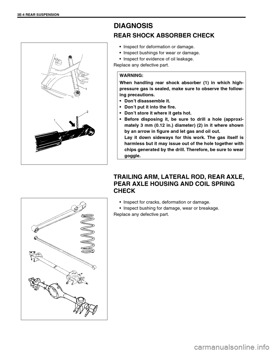
REAR SHOCK ABSORBER CHECK
Inspect for deformation or damage.
Inspect bushings for wear or damage.
Inspect for evidence of oil leakage.
Replace any defective part.
TRAILING ARM, LATERAL ROD, REAR AXLE,
PEAR AXLE HOUSING AND COIL SPRING
CHECK
Inspect for cracks, deformation or damage.
Inspect bushing for damage, wear or breakage.
Replace any defective part.WARNING:
When handling rear shock absorber (1) in which high-
pressure gas is sealed, make sure to observe the follow-
ing precautions.
Don’t disassemble it.
Don’t put it into the fire.
Don’t store it where it gets hot.
Before disposing it, be sure to drill a hole (approxi-
mately 3 mm (0.12 in.) diameter) (2) in it where shown
by an arrow in figure and let gas and oil out.
Lay it down sideways for this work. The gas itself is
harmless but it may issue out of the hole together with
chips generated by the drill. Therefore, be sure to wear
goggle.
Page 220 of 698

REAR SUSPENSION 3E-7
3) Tighten lateral rod nuts (1) to specified torque. It is the most
desirable to have vehicle off hoist and in no-loaded condition
when tightening them.
Tightening torque
Lateral rod left side nut (a) : 50 N·m (5.0 kg-m, 36.5 lb-ft)
Lateral rod right side nut (b) : 65 N·m (6.5 kg-m, 47.0 lb-ft)
REAR SHOCK ABSORBER
REMOVAL
1) Hoist vehicle.
2) Support rear axle (1) (2WD vehicle) or rear axle housing
(4WD vehicle) using floor jack to prevent it from lowering.
3) Remove lower bolt (2).
4) Remove upper bolt (3) and nut (4). Then remove shock
absorber (5).
INSTALLATION
1) Install shock absorber (5) referring to the figure.
Tighten bolt and nut temporarily at this step.
2) Remove floor jack from rear axle (2WD vehicle) or rear axle
housing (4WD vehicle) (1) and lower hoist.
3) Tighten bolt and nut to specified torque.
Tightening torque
Rear shock absorber upper nut
(a) : 63 N·m (6.3 kg-m, 46.0 lb-ft)
Rear shock absorber lower nut
(b) : 58 N·m (5.8 kg-m, 42.0 lb-ft)
COIL SPRING
REMOVAL
1) Hoist vehicle and remove rear wheel (s).
2) Support rear axle (1) (2WD vehicle) or rear axle housing
(4WD vehicle) using floor jack (2) to prevent it from lowering.
A : Vehicle inside
Page 221 of 698

3E-8 REAR SUSPENSION
3) Remove lateral rod right side bolt (1) and nut (2).
4) Detach lateral rod right side from vehicle body.
5) Remove brake flexible hose E-ring (1).
6) Remove LSPV adjust nut and detach spring end from rear
axle (2WD vehicle) or axle housing (4WD vehicle) (if
equipped with LSPV).
7) Remove shock absorber lower bolt (1).
8) Detach shock absorber lower side from rear axle (2WD vehi-
cle) or rear axle housing (4WD vehicle).
9) Lower rear axle (1) (2WD vehicle) or rear axle housing (4WD
vehicle) gradually as far down as where coil springs (2) can
be removed.
10) Remove coil spring.
CAUTION:
Be careful not to let rear axle (2WD vehicle) or rear axle
housing (4WD vehicle) down too much.
It may cause damage to brake flexible hose.
Page 222 of 698

REAR SUSPENSION 3E-9
INSTALLATION
1) Install coil springs (1) (right & left) on spring seat (2) of rear
axle (2WD vehicle) or rear axle housing (4WD vehicle) and
raise rear axle (2WD vehicle) or rear axle housing (4WD
vehicle).
2) Install shock absorber (1) lower side to rear axle (2WD vehi-
cle) or rear axle housing (4WD vehicle).
Tighten shock absorber lower bolt (2) temporarily at this
step.
3) Remove floor jack from rear axle (2WD vehicle) or axle
housing (4WD vehicle).
4) Install brake flexible hose E-ring.
5) Install LSPV spring to rear axle (2WD vehicle) or axle hous-
ing (4WD vehicle). Tighten LSPV adjust nut temporarily at
this step (if equipped with LSPV).
6) Install lateral rod (1) right side to vehicle body, refer to the
figure for proper installing direction of bolt (2).
Tighten nut (3) temporarily at this step.
7) Remove floor jack from rear axle (2WD vehicle) or rear axle
housing (4WD vehicle).
8) Install wheel (1) and tighten wheel nuts (2) to specified
torque.
Tightening torque
Wheel nuts (a) : 85 N·m (8.5 kg-m, 61.5 lb-ft) NOTE:
Upper and lower diameters of coil spring are different.
Bring larger diameter end at bottom and set its open end
in place on spring seat.
A : Upper side
A : Forward
Page 223 of 698

3E-10 REAR SUSPENSION
9) Lower hoist and vehicle in non-loaded condition, tighten
absorber lower bolt (1) and lateral rod right side nut (2) to
specified torque.
Tightening torque
Rear shock absorber lower bolt
(a) : 58 N·m (5.8 kg-m, 42.0 lb-ft)
Lateral rod right side nut
(b) : 65 N·m (6.5 kg-m, 47.0 lb-ft)
10) If equipped with LSPV, check and adjust LSPV spring refer-
ring to “LSPV INSPECTION AND ADJUSTMENT” and per-
form “FLUID PRESSURE TEST” in Section 5.
BUMP STOPPER
REMOVAL
1) Hoist vehicle and remove rear wheel.
2) Remove bump stopper (1) using flat tip rod or the like (2).
INSTALLATION
1) Install bumper stopper.
2) Install wheel (1) and tighten wheel nuts (2) to specified
torque.
Tightening torque
Wheel nuts (a) : 85 N·m (8.5 kg-m, 61.5 lb-ft)
NOTE:
Before installing bushing, apply soap water on it.