ESP SUZUKI SWIFT 2000 1.G RG413 Service User Guide
[x] Cancel search | Manufacturer: SUZUKI, Model Year: 2000, Model line: SWIFT, Model: SUZUKI SWIFT 2000 1.GPages: 698, PDF Size: 16.01 MB
Page 181 of 698
3C-8 STEERING WHEEL AND COLUMN
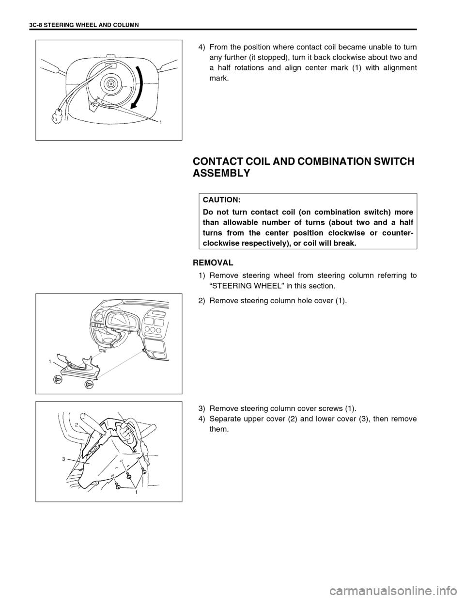
4) From the position where contact coil became unable to turn
any further (it stopped), turn it back clockwise about two and
a half rotations and align center mark (1) with alignment
mark.
CONTACT COIL AND COMBINATION SWITCH
ASSEMBLY
REMOVAL
1) Remove steering wheel from steering column referring to
“STEERING WHEEL” in this section.
2) Remove steering column hole cover (1).
3) Remove steering column cover screws (1).
4) Separate upper cover (2) and lower cover (3), then remove
them.
CAUTION:
Do not turn contact coil (on combination switch) more
than allowable number of turns (about two and a half
turns from the center position clockwise or counter-
clockwise respectively), or coil will break.
1
Page 251 of 698
3F-6 WHEELS AND TIRES
INFLATION OF TIRES
The pressure recommended for any model is carefully calculated to give a satisfactory ride, stability, steering,
tread wear, tire life and resistance to bruises.
Tire pressure, with tires cold, (after vehicle has set for 3 hours or more, or driven less than one mile) should be
checked monthly or before any extended trip. Set to the specifications on the “Tire Placard” located on the left
door (right door for right-hand side steering vehicle) lock pillar.
It is normal for tire pressure to increase when the tires become hot during driving.
Do not bleed or reduce tire pressure after driving. Bleeding reduces the “Cold Inflation Pressure”.
Higher than recommended pressure can cause :
Hard ride
Tire bruising or carcass damage
Rapid tread wear at center of tire
Unequal pressure on same axle can cause :
Uneven braking
Steering lead
Reduced handling
Swerve on acceleration
Lower than recommended pressure can cause :
Tire squeal on turns
Hard Steering
Rapid and uneven wear on the edges of the tread
Tire rim bruises and rupture
Tire cord breakage
High tire temperature
Reduced handling
High fuel consumption
TIRE ROTATION
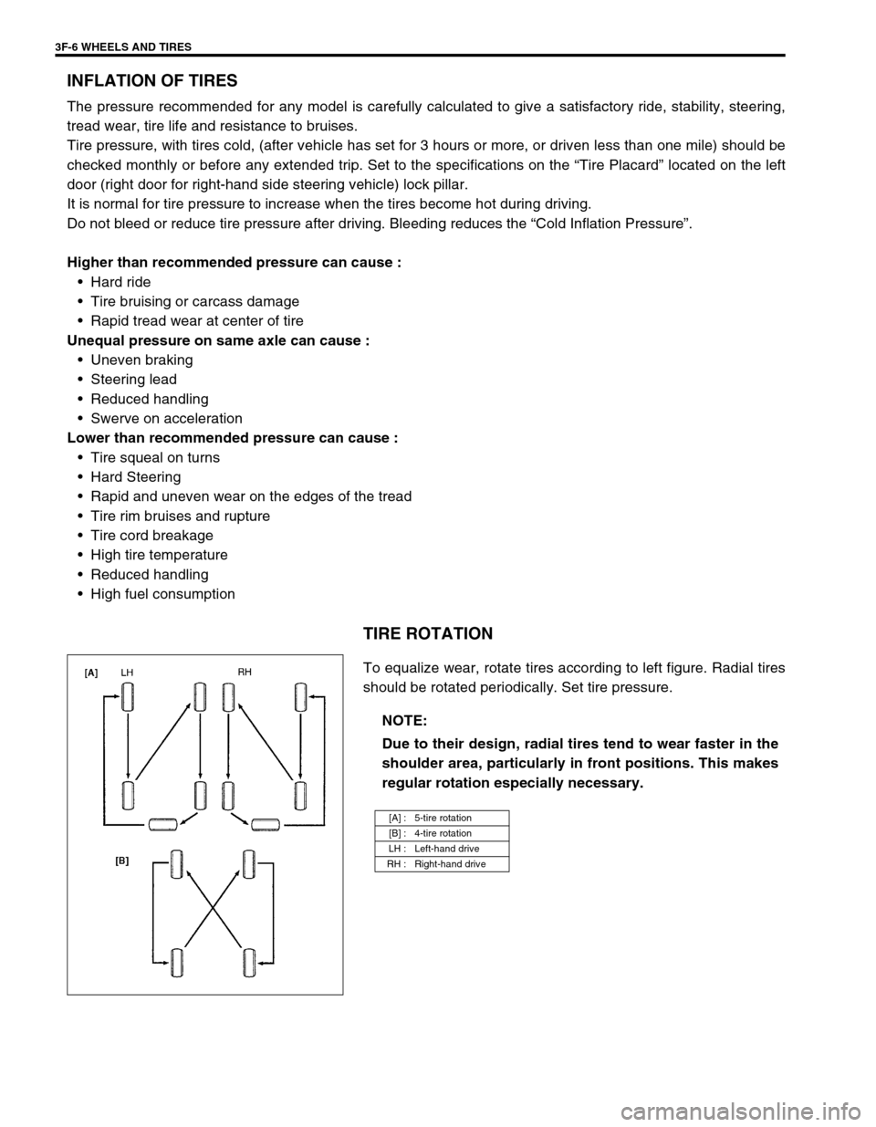
To equalize wear, rotate tires according to left figure. Radial tires
should be rotated periodically. Set tire pressure.
NOTE:
Due to their design, radial tires tend to wear faster in the
shoulder area, particularly in front positions. This makes
regular rotation especially necessary.
[A] : 5-tire rotation
[B] : 4-tire rotation
LH : Left-hand drive
RH : Right-hand drive
Page 261 of 698
4A-8 FRONT DRIVE SHAFT
5) Remove circlip (1) by using flat end rod or the like.
6) Remove center bearing (2) from center bearing support.
ASSEMBLY
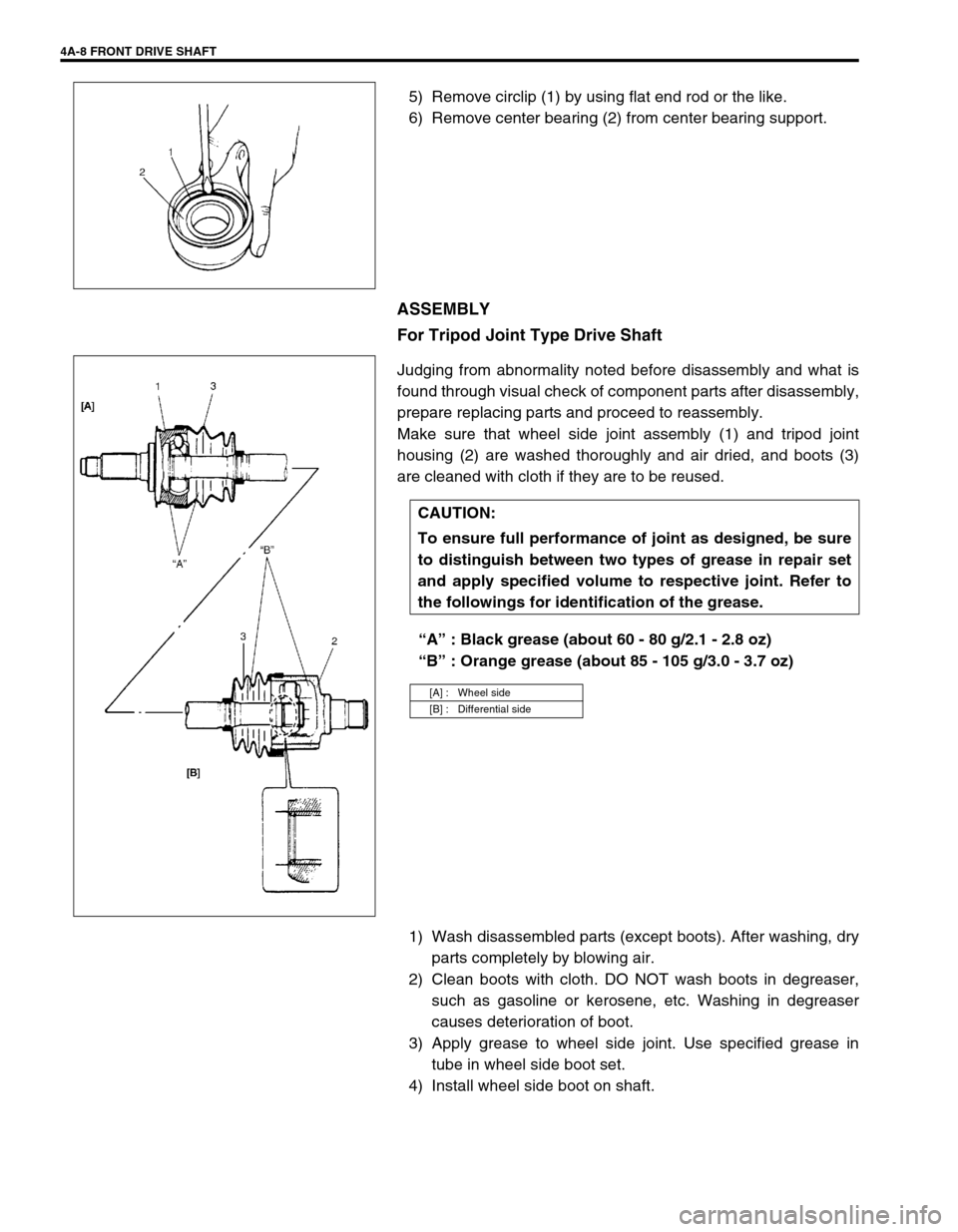
For Tripod Joint Type Drive Shaft
Judging from abnormality noted before disassembly and what is
found through visual check of component parts after disassembly,
prepare replacing parts and proceed to reassembly.
Make sure that wheel side joint assembly (1) and tripod joint
housing (2) are washed thoroughly and air dried, and boots (3)
are cleaned with cloth if they are to be reused.
“A” : Black grease (about 60 - 80 g/2.1 - 2.8 oz)
“B” : Orange grease (about 85 - 105 g/3.0 - 3.7 oz)
1) Wash disassembled parts (except boots). After washing, dry
parts completely by blowing air.
2) Clean boots with cloth. DO NOT wash boots in degreaser,
such as gasoline or kerosene, etc. Washing in degreaser
causes deterioration of boot.
3) Apply grease to wheel side joint. Use specified grease in
tube in wheel side boot set.
4) Install wheel side boot on shaft.
CAUTION:
To ensure full performance of joint as designed, be sure
to distinguish between two types of grease in repair set
and apply specified volume to respective joint. Refer to
the followings for identification of the grease.
[A] : Wheel side
[B] : Differential side
Page 264 of 698
FRONT DRIVE SHAFT 4A-11
For DOJ Type Drive Shaft
Judging from abnormality noted before disassembly and what is
found though visual check of component parts after disassembly,
prepare replacing parts and proceed to reassembly.
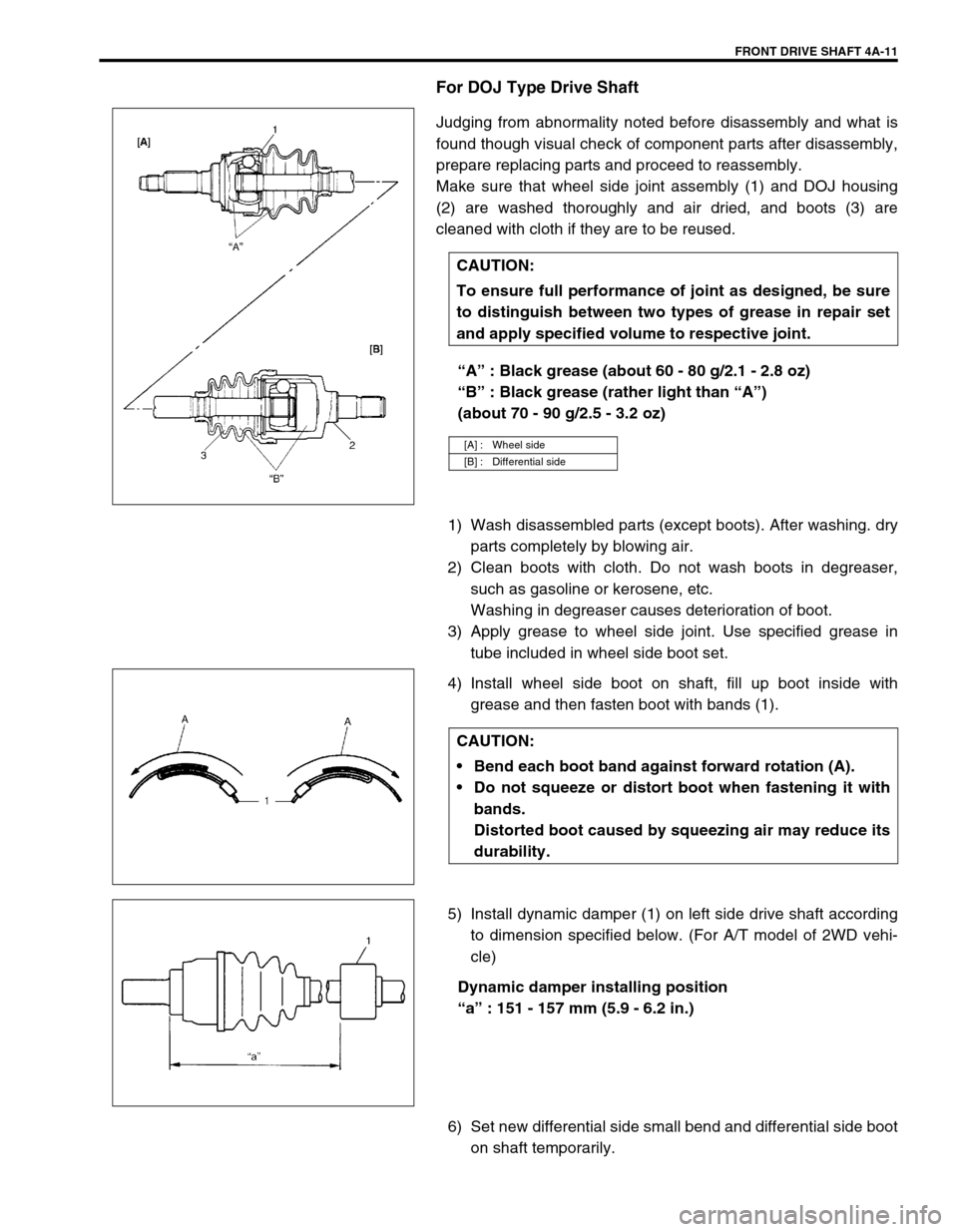
Make sure that wheel side joint assembly (1) and DOJ housing
(2) are washed thoroughly and air dried, and boots (3) are
cleaned with cloth if they are to be reused.
“A” : Black grease (about 60 - 80 g/2.1 - 2.8 oz)
“B” : Black grease (rather light than “A”)
(about 70 - 90 g/2.5 - 3.2 oz)
1) Wash disassembled parts (except boots). After washing. dry
parts completely by blowing air.
2) Clean boots with cloth. Do not wash boots in degreaser,
such as gasoline or kerosene, etc.
Washing in degreaser causes deterioration of boot.
3) Apply grease to wheel side joint. Use specified grease in
tube included in wheel side boot set.
4) Install wheel side boot on shaft, fill up boot inside with
grease and then fasten boot with bands (1).
5) Install dynamic damper (1) on left side drive shaft according
to dimension specified below. (For A/T model of 2WD vehi-
cle)
Dynamic damper installing position
“a” : 151 - 157 mm (5.9 - 6.2 in.)
6) Set new differential side small bend and differential side boot
on shaft temporarily. CAUTION:
To ensure full performance of joint as designed, be sure
to distinguish between two types of grease in repair set
and apply specified volume to respective joint.
[A] : Wheel side
[B] : Differential side
CAUTION:
Bend each boot band against forward rotation (A).
Do not squeeze or distort boot when fastening it with
bands.
Distorted boot caused by squeezing air may reduce its
durability.
Page 283 of 698
5-10 BRAKES
PARKING BRAKE INSPECTION AND
ADJUSTMENT
INSPECTION
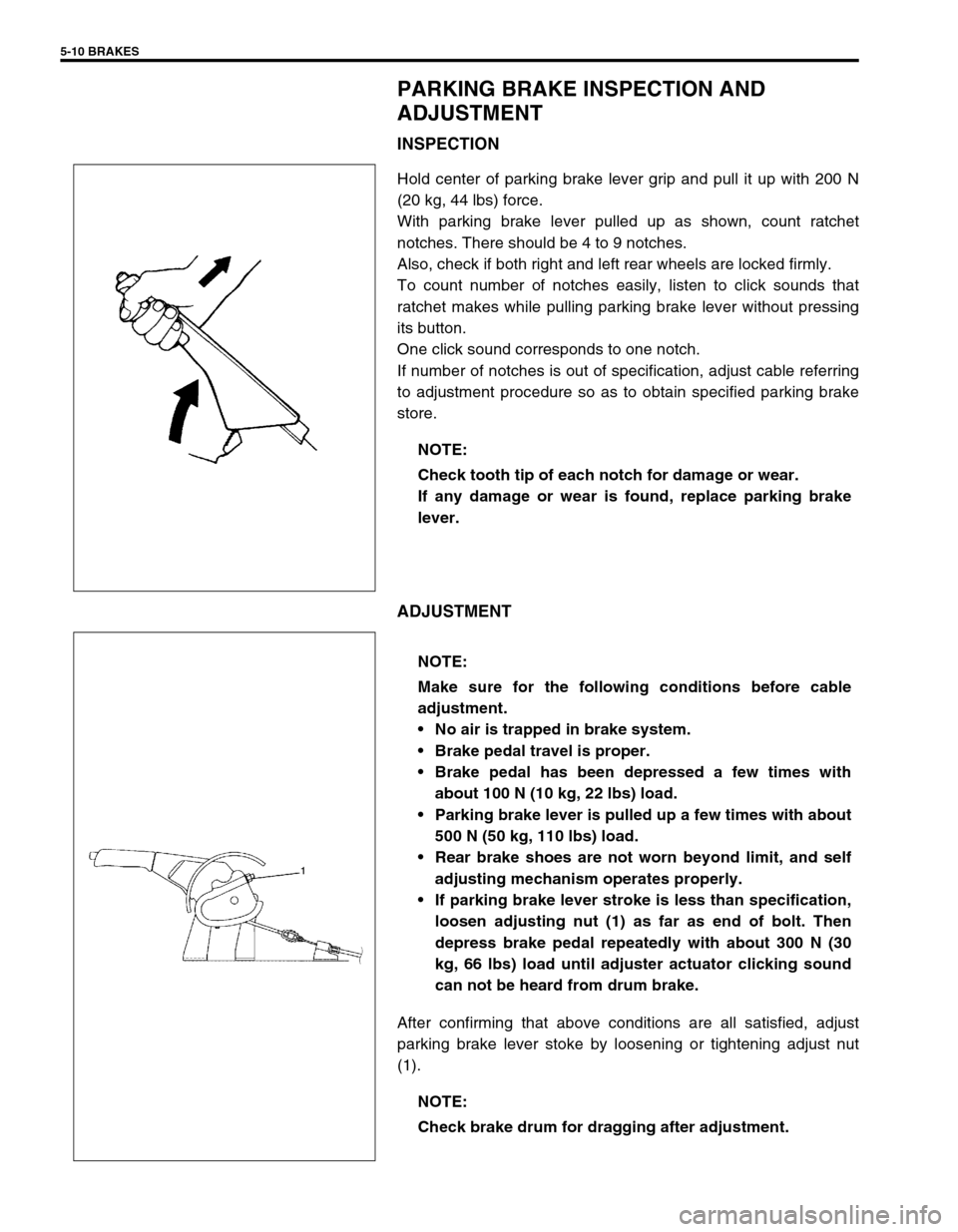
Hold center of parking brake lever grip and pull it up with 200 N
(20 kg, 44 lbs) force.
With parking brake lever pulled up as shown, count ratchet
notches. There should be 4 to 9 notches.
Also, check if both right and left rear wheels are locked firmly.
To count number of notches easily, listen to click sounds that
ratchet makes while pulling parking brake lever without pressing
its button.
One click sound corresponds to one notch.
If number of notches is out of specification, adjust cable referring
to adjustment procedure so as to obtain specified parking brake
store.
ADJUSTMENT
After confirming that above conditions are all satisfied, adjust
parking brake lever stoke by loosening or tightening adjust nut
(1).NOTE:
Check tooth tip of each notch for damage or wear.
If any damage or wear is found, replace parking brake
lever.
NOTE:
Make sure for the following conditions before cable
adjustment.
No air is trapped in brake system.
Brake pedal travel is proper.
Brake pedal has been depressed a few times with
about 100 N (10 kg, 22 lbs) load.
Parking brake lever is pulled up a few times with about
500 N (50 kg, 110 lbs) load.
Rear brake shoes are not worn beyond limit, and self
adjusting mechanism operates properly.
If parking brake lever stroke is less than specification,
loosen adjusting nut (1) as far as end of bolt. Then
depress brake pedal repeatedly with about 300 N (30
kg, 66 lbs) load until adjuster actuator clicking sound
can not be heard from drum brake.
NOTE:
Check brake drum for dragging after adjustment.
Page 286 of 698
BRAKES 5-13
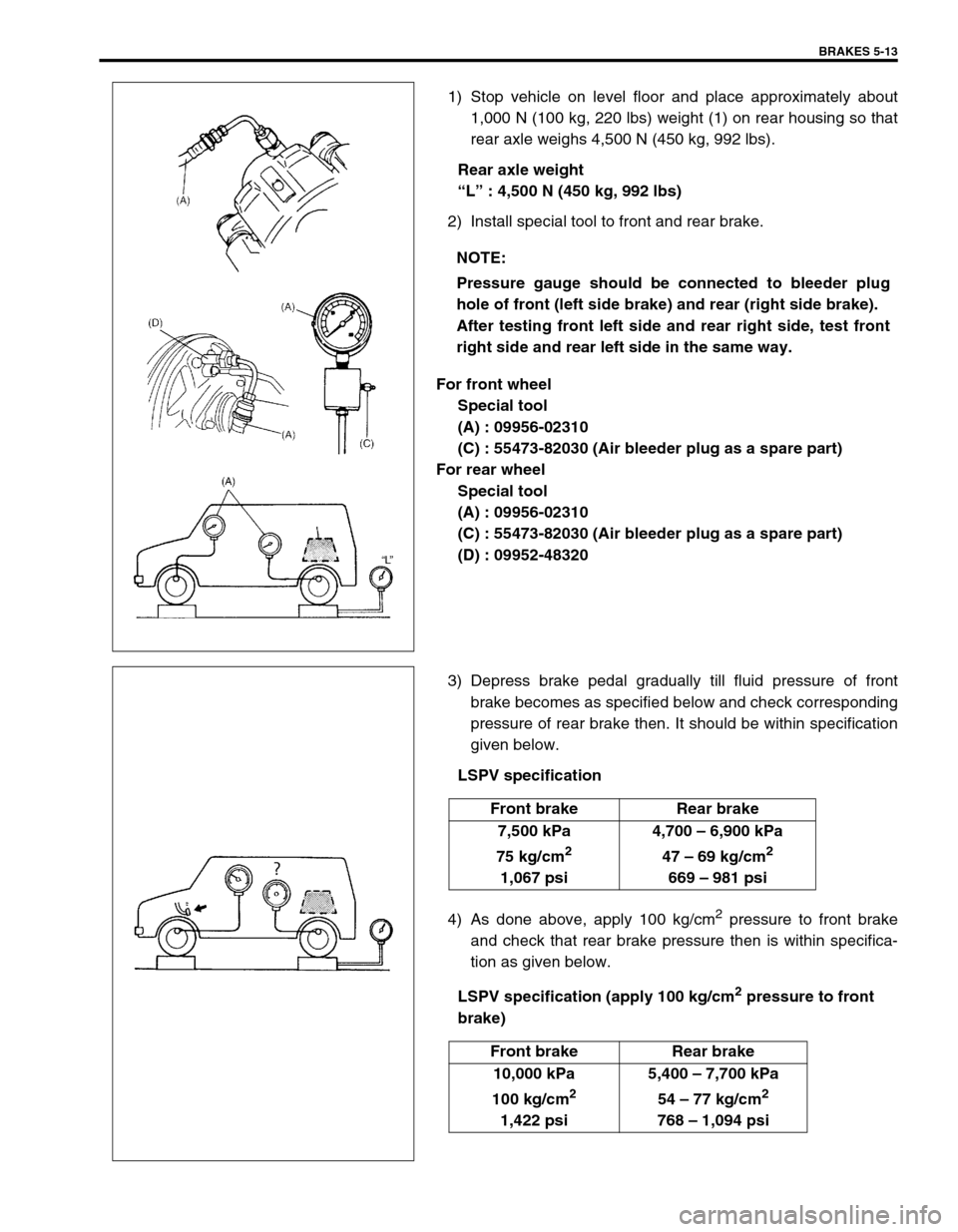
1) Stop vehicle on level floor and place approximately about
1,000 N (100 kg, 220 lbs) weight (1) on rear housing so that
rear axle weighs 4,500 N (450 kg, 992 lbs).
Rear axle weight
“L” : 4,500 N (450 kg, 992 lbs)
2) Install special tool to front and rear brake.
For front wheel
Special tool
(A) : 09956-02310
(C) : 55473-82030 (Air bleeder plug as a spare part)
For rear wheel
Special tool
(A) : 09956-02310
(C) : 55473-82030 (Air bleeder plug as a spare part)
(D) : 09952-48320
3) Depress brake pedal gradually till fluid pressure of front
brake becomes as specified below and check corresponding
pressure of rear brake then. It should be within specification
given below.
LSPV specification
4) As done above, apply 100 kg/cm
2 pressure to front brake
and check that rear brake pressure then is within specifica-
tion as given below.
LSPV specification (apply 100 kg/cm
2 pressure to front
brake) NOTE:
Pressure gauge should be connected to bleeder plug
hole of front (left side brake) and rear (right side brake).
After testing front left side and rear right side, test front
right side and rear left side in the same way.
Front brake Rear brake
7,500 kPa
75 kg/cm
2
1,067 psi4,700 – 6,900 kPa
47 – 69 kg/cm
2
669 – 981 psi
Front brake Rear brake
10,000 kPa
100 kg/cm
2
1,422 psi5,400 – 7,700 kPa
54 – 77 kg/cm
2
768 – 1,094 psi
Page 322 of 698
BRAKES 5-49
INSTALLATION
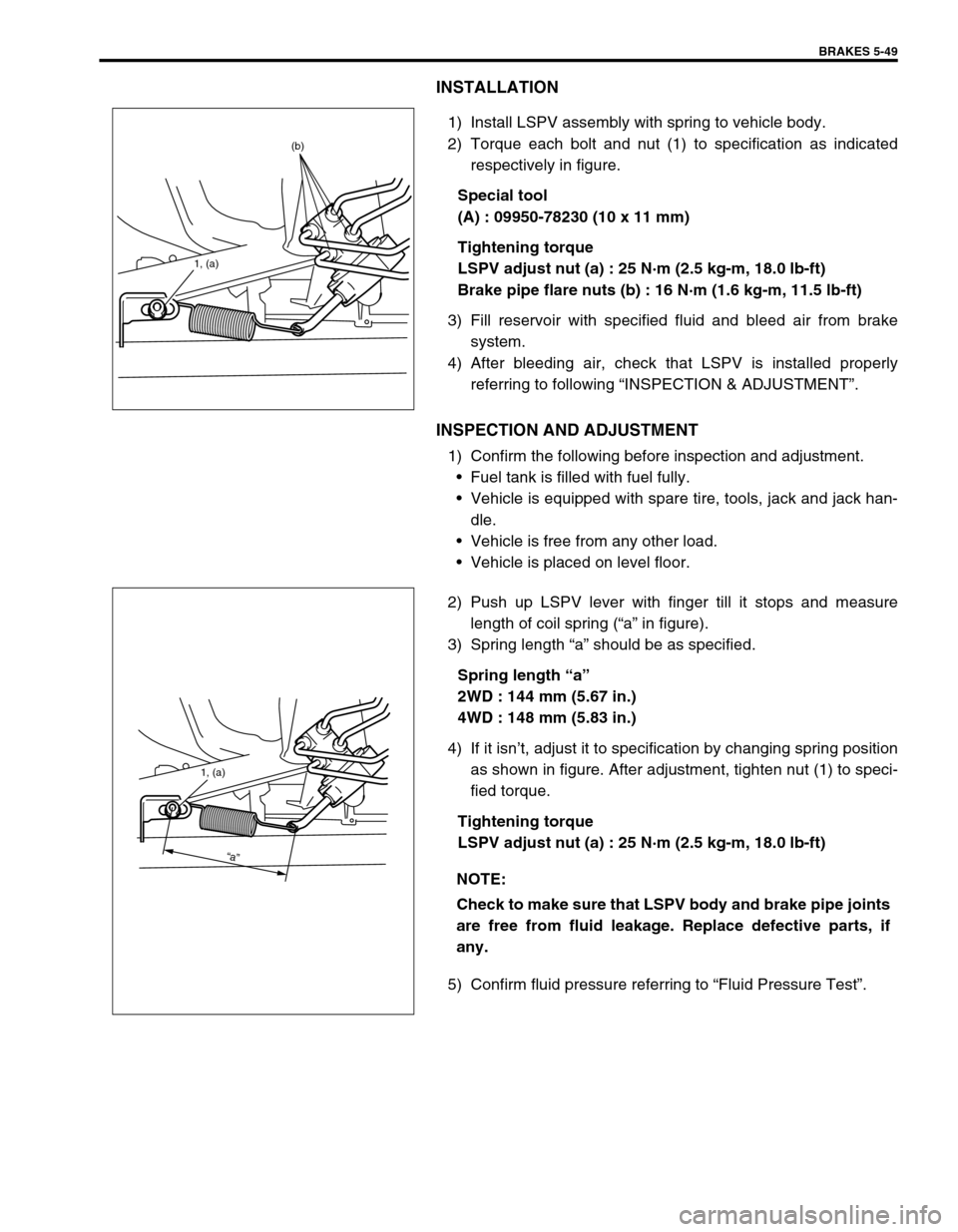
1) Install LSPV assembly with spring to vehicle body.
2) Torque each bolt and nut (1) to specification as indicated
respectively in figure.
Special tool
(A) : 09950-78230 (10 x 11 mm)
Tightening torque
LSPV adjust nut (a) : 25 N·m (2.5 kg-m, 18.0 lb-ft)
Brake pipe flare nuts (b) : 16 N·m (1.6 kg-m, 11.5 lb-ft)
3) Fill reservoir with specified fluid and bleed air from brake
system.
4) After bleeding air, check that LSPV is installed properly
referring to following “INSPECTION & ADJUSTMENT”.
INSPECTION AND ADJUSTMENT
1) Confirm the following before inspection and adjustment.
Fuel tank is filled with fuel fully.
Vehicle is equipped with spare tire, tools, jack and jack han-
dle.
Vehicle is free from any other load.
Vehicle is placed on level floor.
2) Push up LSPV lever with finger till it stops and measure
length of coil spring (“a” in figure).
3) Spring length “a” should be as specified.
Spring length “a”
2WD : 144 mm (5.67 in.)
4WD : 148 mm (5.83 in.)
4) If it isn’t, adjust it to specification by changing spring position
as shown in figure. After adjustment, tighten nut (1) to speci-
fied torque.
Tightening torque
LSPV adjust nut (a) : 25 N·m (2.5 kg-m, 18.0 lb-ft)
5) Confirm fluid pressure referring to “Fluid Pressure Test”.
1, (a)
(b)
NOTE:
Check to make sure that LSPV body and brake pipe joints
are free from fluid leakage. Replace defective parts, if
any.
1, (a)
“a”
Page 350 of 698
ANTILOCK BRAKE SYSTEM (ABS) 5E-25
INSPECTION
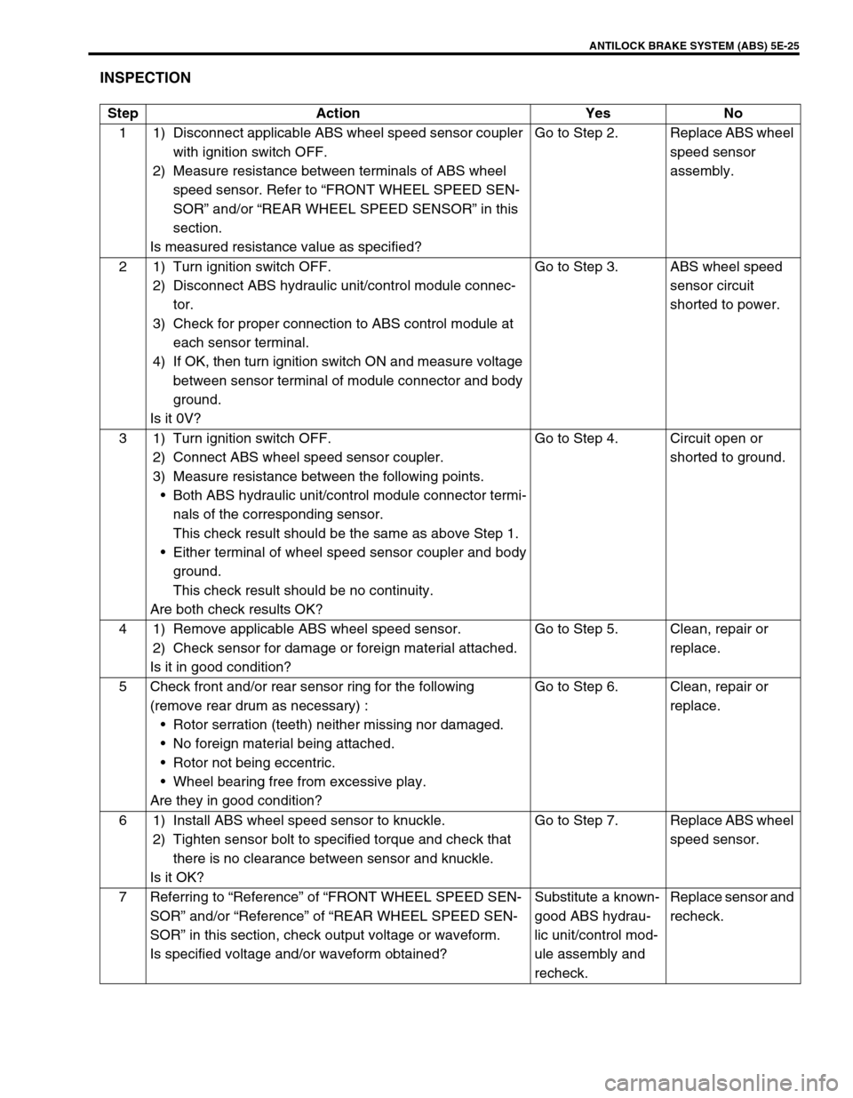
Step Action Yes No
1 1) Disconnect applicable ABS wheel speed sensor coupler
with ignition switch OFF.
2) Measure resistance between terminals of ABS wheel
speed sensor. Refer to “FRONT WHEEL SPEED SEN-
SOR” and/or “REAR WHEEL SPEED SENSOR” in this
section.
Is measured resistance value as specified?Go to Step 2. Replace ABS wheel
speed sensor
assembly.
2 1) Turn ignition switch OFF.
2) Disconnect ABS hydraulic unit/control module connec-
tor.
3) Check for proper connection to ABS control module at
each sensor terminal.
4) If OK, then turn ignition switch ON and measure voltage
between sensor terminal of module connector and body
ground.
Is it 0V?Go to Step 3. ABS wheel speed
sensor circuit
shorted to power.
3 1) Turn ignition switch OFF.
2) Connect ABS wheel speed sensor coupler.
3) Measure resistance between the following points.
Both ABS hydraulic unit/control module connector termi-
nals of the corresponding sensor.
This check result should be the same as above Step 1.
Either terminal of wheel speed sensor coupler and body
ground.
This check result should be no continuity.
Are both check results OK?Go to Step 4. Circuit open or
shorted to ground.
4 1) Remove applicable ABS wheel speed sensor.
2) Check sensor for damage or foreign material attached.
Is it in good condition?Go to Step 5. Clean, repair or
replace.
5 Check front and/or rear sensor ring for the following
(remove rear drum as necessary) :
Rotor serration (teeth) neither missing nor damaged.
No foreign material being attached.
Rotor not being eccentric.
Wheel bearing free from excessive play.
Are they in good condition?Go to Step 6. Clean, repair or
replace.
6 1) Install ABS wheel speed sensor to knuckle.
2) Tighten sensor bolt to specified torque and check that
there is no clearance between sensor and knuckle.
Is it OK?Go to Step 7. Replace ABS wheel
speed sensor.
7 Referring to “Reference” of “FRONT WHEEL SPEED SEN-
SOR” and/or “Reference” of “REAR WHEEL SPEED SEN-
SOR” in this section, check output voltage or waveform.
Is specified voltage and/or waveform obtained?Substitute a known-
good ABS hydrau-
lic unit/control mod-
ule assembly and
recheck.Replace sensor and
recheck.
Page 371 of 698
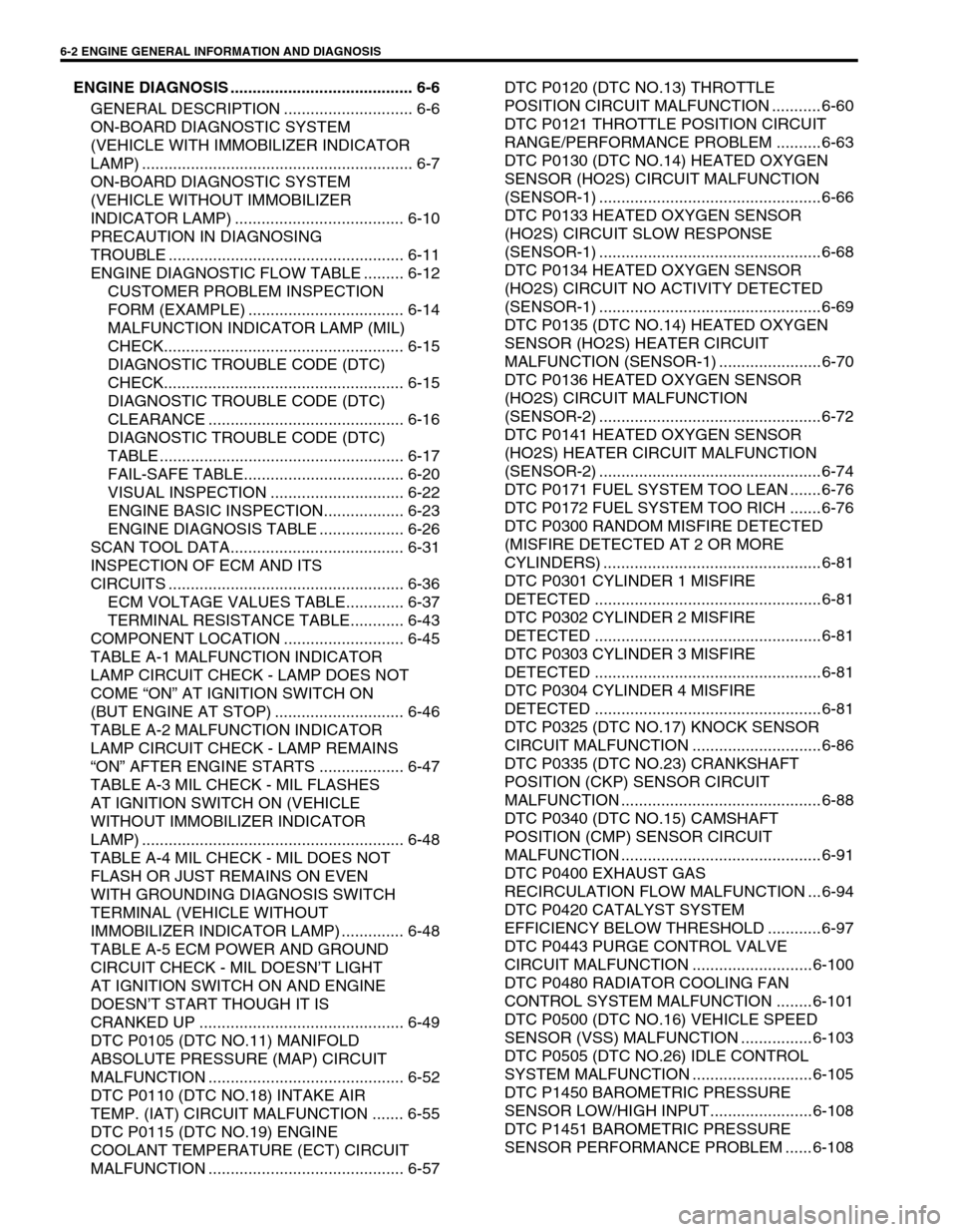
6-2 ENGINE GENERAL INFORMATION AND DIAGNOSIS
ENGINE DIAGNOSIS ......................................... 6-6
GENERAL DESCRIPTION ............................. 6-6
ON-BOARD DIAGNOSTIC SYSTEM
(VEHICLE WITH IMMOBILIZER INDICATOR
LAMP) ............................................................. 6-7
ON-BOARD DIAGNOSTIC SYSTEM
(VEHICLE WITHOUT IMMOBILIZER
INDICATOR LAMP) ...................................... 6-10
PRECAUTION IN DIAGNOSING
TROUBLE ..................................................... 6-11
ENGINE DIAGNOSTIC FLOW TABLE ......... 6-12
CUSTOMER PROBLEM INSPECTION
FORM (EXAMPLE) ................................... 6-14
MALFUNCTION INDICATOR LAMP (MIL)
CHECK...................................................... 6-15
DIAGNOSTIC TROUBLE CODE (DTC)
CHECK...................................................... 6-15
DIAGNOSTIC TROUBLE CODE (DTC)
CLEARANCE ............................................ 6-16
DIAGNOSTIC TROUBLE CODE (DTC)
TABLE ....................................................... 6-17
FAIL-SAFE TABLE.................................... 6-20
VISUAL INSPECTION .............................. 6-22
ENGINE BASIC INSPECTION.................. 6-23
ENGINE DIAGNOSIS TABLE ................... 6-26
SCAN TOOL DATA....................................... 6-31
INSPECTION OF ECM AND ITS
CIRCUITS ..................................................... 6-36
ECM VOLTAGE VALUES TABLE............. 6-37
TERMINAL RESISTANCE TABLE............ 6-43
COMPONENT LOCATION ........................... 6-45
TABLE A-1 MALFUNCTION INDICATOR
LAMP CIRCUIT CHECK - LAMP DOES NOT
COME “ON” AT IGNITION SWITCH ON
(BUT ENGINE AT STOP) ............................. 6-46
TABLE A-2 MALFUNCTION INDICATOR
LAMP CIRCUIT CHECK - LAMP REMAINS
“ON” AFTER ENGINE STARTS ................... 6-47
TABLE A-3 MIL CHECK - MIL FLASHES
AT IGNITION SWITCH ON (VEHICLE
WITHOUT IMMOBILIZER INDICATOR
LAMP) ........................................................... 6-48
TABLE A-4 MIL CHECK - MIL DOES NOT
FLASH OR JUST REMAINS ON EVEN
WITH GROUNDING DIAGNOSIS SWITCH
TERMINAL (VEHICLE WITHOUT
IMMOBILIZER INDICATOR LAMP) .............. 6-48
TABLE A-5 ECM POWER AND GROUND
CIRCUIT CHECK - MIL DOESN’T LIGHT
AT IGNITION SWITCH ON AND ENGINE
DOESN’T START THOUGH IT IS
CRANKED UP .............................................. 6-49
DTC P0105 (DTC NO.11) MANIFOLD
ABSOLUTE PRESSURE (MAP) CIRCUIT
MALFUNCTION ............................................ 6-52
DTC P0110 (DTC NO.18) INTAKE AIR
TEMP. (IAT) CIRCUIT MALFUNCTION ....... 6-55
DTC P0115 (DTC NO.19) ENGINE
COOLANT TEMPERATURE (ECT) CIRCUIT
MALFUNCTION ............................................ 6-57DTC P0120 (DTC NO.13) THROTTLE
POSITION CIRCUIT MALFUNCTION ........... 6-60
DTC P0121 THROTTLE POSITION CIRCUIT
RANGE/PERFORMANCE PROBLEM .......... 6-63
DTC P0130 (DTC NO.14) HEATED OXYGEN
SENSOR (HO2S) CIRCUIT MALFUNCTION
(SENSOR-1) .................................................. 6-66
DTC P0133 HEATED OXYGEN SENSOR
(HO2S) CIRCUIT SLOW RESPONSE
(SENSOR-1) .................................................. 6-68
DTC P0134 HEATED OXYGEN SENSOR
(HO2S) CIRCUIT NO ACTIVITY DETECTED
(SENSOR-1) .................................................. 6-69
DTC P0135 (DTC NO.14) HEATED OXYGEN
SENSOR (HO2S) HEATER CIRCUIT
MALFUNCTION (SENSOR-1) ....................... 6-70
DTC P0136 HEATED OXYGEN SENSOR
(HO2S) CIRCUIT MALFUNCTION
(SENSOR-2) .................................................. 6-72
DTC P0141 HEATED OXYGEN SENSOR
(HO2S) HEATER CIRCUIT MALFUNCTION
(SENSOR-2) .................................................. 6-74
DTC P0171 FUEL SYSTEM TOO LEAN ....... 6-76
DTC P0172 FUEL SYSTEM TOO RICH ....... 6-76
DTC P0300 RANDOM MISFIRE DETECTED
(MISFIRE DETECTED AT 2 OR MORE
CYLINDERS) ................................................. 6-81
DTC P0301 CYLINDER 1 MISFIRE
DETECTED ................................................... 6-81
DTC P0302 CYLINDER 2 MISFIRE
DETECTED ................................................... 6-81
DTC P0303 CYLINDER 3 MISFIRE
DETECTED ................................................... 6-81
DTC P0304 CYLINDER 4 MISFIRE
DETECTED ................................................... 6-81
DTC P0325 (DTC NO.17) KNOCK SENSOR
CIRCUIT MALFUNCTION ............................. 6-86
DTC P0335 (DTC NO.23) CRANKSHAFT
POSITION (CKP) SENSOR CIRCUIT
MALFUNCTION ............................................. 6-88
DTC P0340 (DTC NO.15) CAMSHAFT
POSITION (CMP) SENSOR CIRCUIT
MALFUNCTION ............................................. 6-91
DTC P0400 EXHAUST GAS
RECIRCULATION FLOW MALFUNCTION ... 6-94
DTC P0420 CATALYST SYSTEM
EFFICIENCY BELOW THRESHOLD ............ 6-97
DTC P0443 PURGE CONTROL VALVE
CIRCUIT MALFUNCTION ........................... 6-100
DTC P0480 RADIATOR COOLING FAN
CONTROL SYSTEM MALFUNCTION ........ 6-101
DTC P0500 (DTC NO.16) VEHICLE SPEED
SENSOR (VSS) MALFUNCTION ................ 6-103
DTC P0505 (DTC NO.26) IDLE CONTROL
SYSTEM MALFUNCTION ........................... 6-105
DTC P1450 BAROMETRIC PRESSURE
SENSOR LOW/HIGH INPUT....................... 6-108
DTC P1451 BAROMETRIC PRESSURE
SENSOR PERFORMANCE PROBLEM ...... 6-108
Page 380 of 698
ENGINE GENERAL INFORMATION AND DIAGNOSIS 6-11
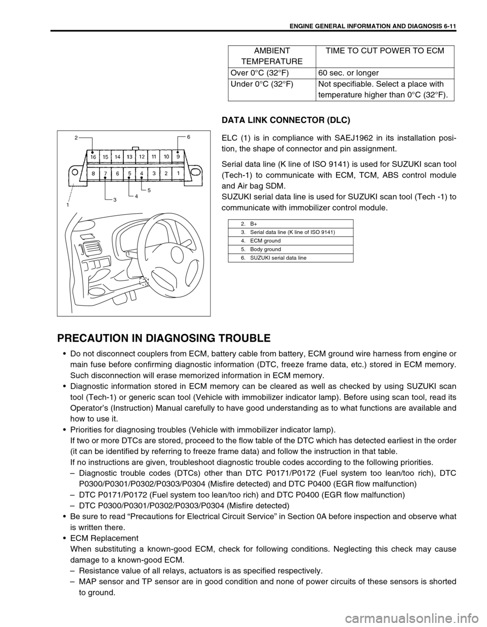
DATA LINK CONNECTOR (DLC)
ELC (1) is in compliance with SAEJ1962 in its installation posi-
tion, the shape of connector and pin assignment.
Serial data line (K line of ISO 9141) is used for SUZUKI scan tool
(Tech-1) to communicate with ECM, TCM, ABS control module
and Air bag SDM.
SUZUKI serial data line is used for SUZUKI scan tool (Tech -1) to
communicate with immobilizer control module.
PRECAUTION IN DIAGNOSING TROUBLE
Do not disconnect couplers from ECM, battery cable from battery, ECM ground wire harness from engine or
main fuse before confirming diagnostic information (DTC, freeze frame data, etc.) stored in ECM memory.
Such disconnection will erase memorized information in ECM memory.
Diagnostic information stored in ECM memory can be cleared as well as checked by using SUZUKI scan
tool (Tech-1) or generic scan tool (Vehicle with immobilizer indicator lamp). Before using scan tool, read its
Operator’s (Instruction) Manual carefully to have good understanding as to what functions are available and
how to use it.
Priorities for diagnosing troubles (Vehicle with immobilizer indicator lamp).
If two or more DTCs are stored, proceed to the flow table of the DTC which has detected earliest in the order
(it can be identified by referring to freeze frame data) and follow the instruction in that table.
If no instructions are given, troubleshoot diagnostic trouble codes according to the following priorities.
–Diagnostic trouble codes (DTCs) other than DTC P0171/P0172 (Fuel system too lean/too rich), DTC
P0300/P0301/P0302/P0303/P0304 (Misfire detected) and DTC P0400 (EGR flow malfunction)
–DTC P0171/P0172 (Fuel system too lean/too rich) and DTC P0400 (EGR flow malfunction)
–DTC P0300/P0301/P0302/P0303/P0304 (Misfire detected)
Be sure to read “Precautions for Electrical Circuit Service” in Section 0A before inspection and observe what
is written there.
ECM Replacement
When substituting a known-good ECM, check for following conditions. Neglecting this check may cause
damage to a known-good ECM.
–Resistance value of all relays, actuators is as specified respectively.
–MAP sensor and TP sensor are in good condition and none of power circuits of these sensors is shorted
to ground.AMBIENT
TEMPERATURETIME TO CUT POWER TO ECM
Over 0°C (32°F) 60 sec. or longer
Under 0°C (32°F) Not specifiable. Select a place with
temperature higher than 0°C (32°F).
2. B+
3. Serial data line (K line of ISO 9141)
4. ECM ground
5. Body ground
6. SUZUKI serial data line
2
3456
1