change wheel SUZUKI SWIFT 2000 1.G RG413 Service Workshop Manual
[x] Cancel search | Manufacturer: SUZUKI, Model Year: 2000, Model line: SWIFT, Model: SUZUKI SWIFT 2000 1.GPages: 698, PDF Size: 16.01 MB
Page 32 of 698
MAINTENANCE AND LUBRICATION 0B-3
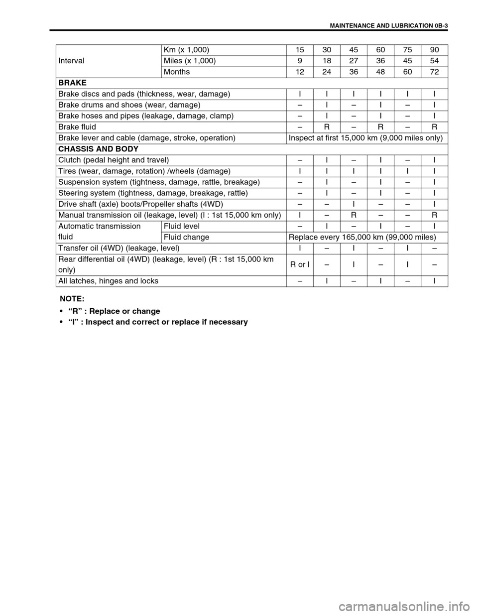
IntervalKm (x 1,000) 153045607590
Miles (x 1,000) 9 18 27 36 45 54
Months 12 24 36 48 60 72
BRAKE
Brake discs and pads (thickness, wear, damage) I I I I I I
Brake drums and shoes (wear, damage)–I–I–I
Brake hoses and pipes (leakage, damage, clamp)–I–I–I
Brake fluid–R–R–R
Brake lever and cable (damage, stroke, operation) Inspect at first 15,000 km (9,000 miles only)
CHASSIS AND BODY
Clutch (pedal height and travel)–I–I–I
Tires (wear, damage, rotation) /wheels (damage) I I I I I I
Suspension system (tightness, damage, rattle, breakage)–I–I–I
Steering system (tightness, damage, breakage, rattle)–I–I–I
Drive shaft (axle) boots/Propeller shafts (4WD)––I––I
Manual transmission oil (leakage, level) (I : 1st 15,000 km only) I–R––R
Automatic transmission
fluidFluid level–I–I–I
Fluid change Replace every 165,000 km (99,000 miles)
Transfer oil (4WD) (leakage, level) I–I–I–
Rear differential oil (4WD) (leakage, level) (R : 1st 15,000 km
only)R or I–I–I–
All latches, hinges and locks–I–I–I
NOTE:
“R” : Replace or change
“I” : Inspect and correct or replace if necessary
Page 33 of 698
0B-4 MAINTENANCE AND LUBRICATION
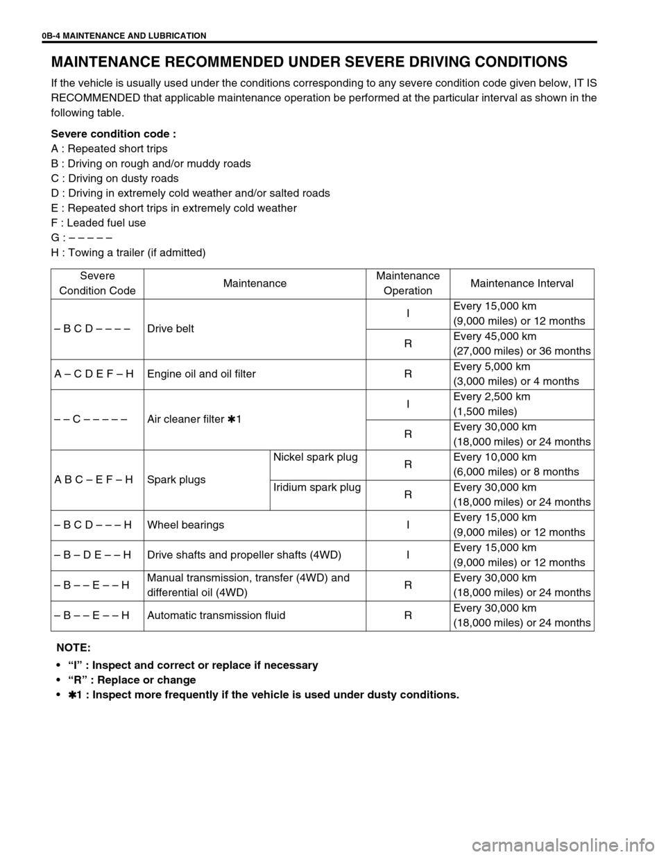
MAINTENANCE RECOMMENDED UNDER SEVERE DRIVING CONDITIONS
If the vehicle is usually used under the conditions corresponding to any severe condition code given below, IT IS
RECOMMENDED that applicable maintenance operation be performed at the particular interval as shown in the
following table.
Severe condition code :
A : Repeated short trips
B : Driving on rough and/or muddy roads
C : Driving on dusty roads
D : Driving in extremely cold weather and/or salted roads
E : Repeated short trips in extremely cold weather
F : Leaded fuel use
G : – – – – –
H : Towing a trailer (if admitted)
Severe
Condition CodeMaintenanceMaintenance
OperationMaintenance Interval
– B C D – – – –Drive beltIEvery 15,000 km
(9,000 miles) or 12 months
REvery 45,000 km
(27,000 miles) or 36 months
A – C D E F – H Engine oil and oil filter REvery 5,000 km
(3,000 miles) or 4 months
– – C – – – – –Air cleaner filter ✱1IEvery 2,500 km
(1,500 miles)
REvery 30,000 km
(18,000 miles) or 24 months
A B C – E F – H Spark plugsNickel spark plug
REvery 10,000 km
(6,000 miles) or 8 months
Iridium spark plug
REvery 30,000 km
(18,000 miles) or 24 months
– B C D – – – H Wheel bearings IEvery 15,000 km
(9,000 miles) or 12 months
– B – D E – – H Drive shafts and propeller shafts (4WD) IEvery 15,000 km
(9,000 miles) or 12 months
– B – – E – – HManual transmission, transfer (4WD) and
differential oil (4WD)REvery 30,000 km
(18,000 miles) or 24 months
– B – – E – – H Automatic transmission fluid REvery 30,000 km
(18,000 miles) or 24 months
NOTE:
“I” : Inspect and correct or replace if necessary
“R” : Replace or change
✱
✱✱ ✱1 : Inspect more frequently if the vehicle is used under dusty conditions.
Page 42 of 698
MAINTENANCE AND LUBRICATION 0B-13
BRAKE DRUMS AND SHOES (REAR)
INSPECTION
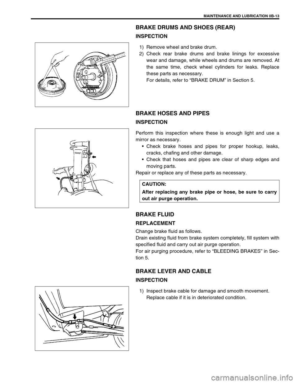
1) Remove wheel and brake drum.
2) Check rear brake drums and brake linings for excessive
wear and damage, while wheels and drums are removed. At
the same time, check wheel cylinders for leaks. Replace
these parts as necessary.
For details, refer to “BRAKE DRUM” in Section 5.
BRAKE HOSES AND PIPES
INSPECTION
Perform this inspection where these is enough light and use a
mirror as necessary.
Check brake hoses and pipes for proper hookup, leaks,
cracks, chafing and other damage.
Check that hoses and pipes are clear of sharp edges and
moving parts.
Repair or replace any of these parts as necessary.
BRAKE FLUID
REPLACEMENT
Change brake fluid as follows.
Drain existing fluid from brake system completely, fill system with
specified fluid and carry out air purge operation.
For air purging procedure, refer to “BLEEDING BRAKES” in Sec-
tion 5.
BRAKE LEVER AND CABLE
INSPECTION
1) Inspect brake cable for damage and smooth movement.
Replace cable if it is in deteriorated condition.
CAUTION:
After replacing any brake pipe or hose, be sure to carry
out air purge operation.
Page 50 of 698
MAINTENANCE AND LUBRICATION 0B-21
STEERING
Check to ensure that steering wheel is free from instability, or abnormally heavy feeling.
Check that the vehicle does not wander or pull to one side.
ENGINE
Check that engine responds readily at all speeds.
Check that engine is free from abnormal noise and abnormal vibration.
BODY, WHEELS AND POWER TRANSMITTING SYSTEM
Check that body, wheels and power transmitting system are free from abnormal noise and abnormal vibration or
any other abnormal condition.
METERS AND GAUGE
Check that speedometer, odometer, fuel meter, temperature gauge, etc. are operating accurately.
LIGHTS
Check that all lights operate properly.
WINDSHIELD DEFROSTER
Periodically check that air comes out from defroster outlet when operating heater or air conditioning.
Set mode control lever to defroster position and fan switch lever to “HI” position for this check.
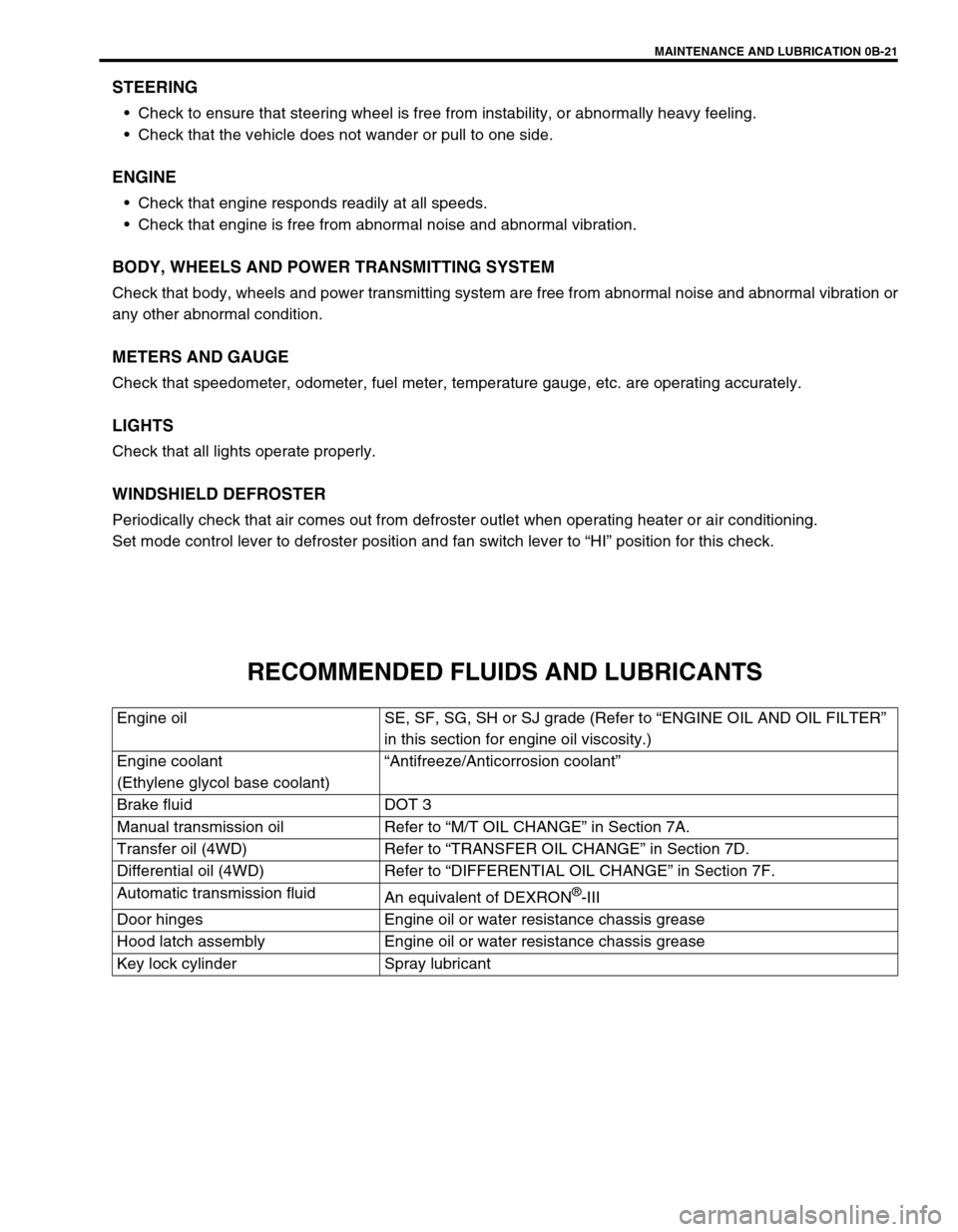
RECOMMENDED FLUIDS AND LUBRICANTS
Engine oil SE, SF, SG, SH or SJ grade (Refer to “ENGINE OIL AND OIL FILTER”
in this section for engine oil viscosity.)
Engine coolant
(Ethylene glycol base coolant)“Antifreeze/Anticorrosion coolant”
Brake fluid DOT 3
Manual transmission oil Refer to “M/T OIL CHANGE” in Section 7A.
Transfer oil (4WD) Refer to “TRANSFER OIL CHANGE” in Section 7D.
Differential oil (4WD) Refer to “DIFFERENTIAL OIL CHANGE” in Section 7F.
Automatic transmission fluid
An equivalent of DEXRON
®-III
Door hinges Engine oil or water resistance chassis grease
Hood latch assembly Engine oil or water resistance chassis grease
Key lock cylinder Spray lubricant
Page 121 of 698
3A-4 FRONT END ALIGNMENT
CAMBER AND CASTER CHECK AND
ADJUSTMENT
Should camber or caster be found out of specifications upon
inspection, locate its cause first.
If it is in damaged, loose, bent, dented or worn suspension parts,
they should be replaced.
If it is in vehicle body, repair it so as to attain specifications.
STEERING ANGLE CHECK AND ADJUST-
MENT
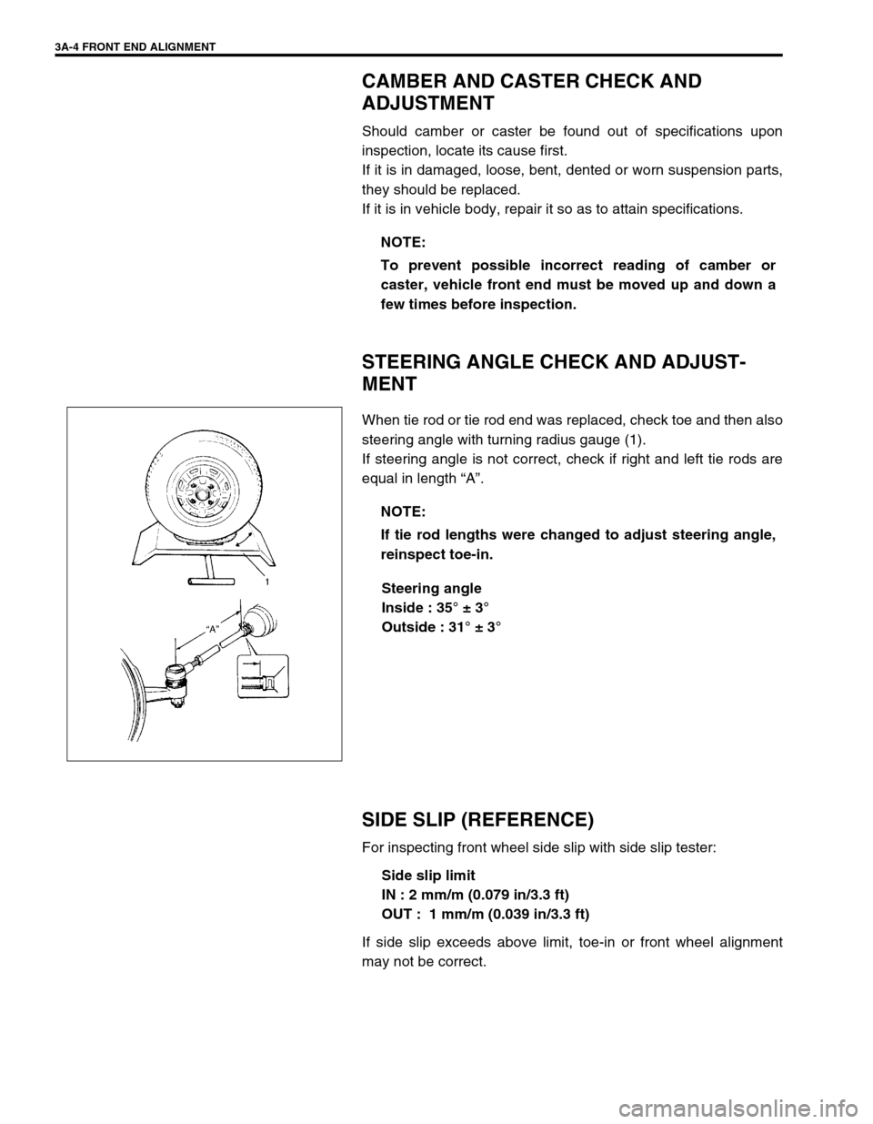
When tie rod or tie rod end was replaced, check toe and then also
steering angle with turning radius gauge (1).
If steering angle is not correct, check if right and left tie rods are
equal in length “A”.
Steering angle
Inside : 35° ± 3°
Outside : 31° ± 3°
SIDE SLIP (REFERENCE)
For inspecting front wheel side slip with side slip tester:
Side slip limit
IN : 2 mm/m (0.079 in/3.3 ft)
OUT : 1 mm/m (0.039 in/3.3 ft)
If side slip exceeds above limit, toe-in or front wheel alignment
may not be correct.NOTE:
To prevent possible incorrect reading of camber or
caster, vehicle front end must be moved up and down a
few times before inspection.
NOTE:
If tie rod lengths were changed to adjust steering angle,
reinspect toe-in.
Page 123 of 698
3B-2 MANUAL RACK AND PINION
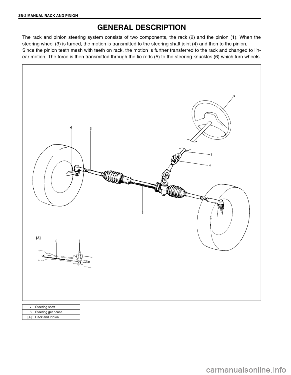
GENERAL DESCRIPTION
The rack and pinion steering system consists of two components, the rack (2) and the pinion (1). When the
steering wheel (3) is turned, the motion is transmitted to the steering shaft joint (4) and then to the pinion.
Since the pinion teeth mesh with teeth on rack, the motion is further transferred to the rack and changed to lin-
ear motion. The force is then transmitted through the tie rods (5) to the steering knuckles (6) which turn wheels.
7. Steering shaft
8. Steering gear case
[A]: Rack and Pinion
Page 253 of 698
3F-8 WHEELS AND TIRES
TIRE
MOUNTING AND DISMOUNTING
Use a tire changing machine to mount or dismount tires. Follow equipment manufacturer’s instructions. Do not
use hand tools or tire irons alone to change tires as they may damage tire beads or wheel rim.
Rim bead seats should be cleaned with a wire brush or coarse steel wool to remove lubricants, old rubber and
light rust. Before mounting or dismounting a tire, bead area should be well lubricated with approved tire lubri-
cant.
After mounting, inflate to specified pressure shown on tire placard so that beads are completely seated.
Install valve core and inflate to proper pressure.
REPAIR
There are many different materials and techniques on the market to repair tires. As not all of these work on all
types of tires, tire manufacturers have published detailed instructions on how and when to repair tires. These
instructions can be obtained from each tire manufacturer.WARNING:
Do not stand over tire when inflating. Bead may break when bead snaps over rim’s safety hump and
cause serious personal injury.
Do not exceed specified pressure when inflating. If specified pressure will not seat beads, deflate, re-
lubricate and reinflate.
Over inflation may cause bead to break and cause serious personal injury.
Page 328 of 698
ANTILOCK BRAKE SYSTEM (ABS) 5E-3
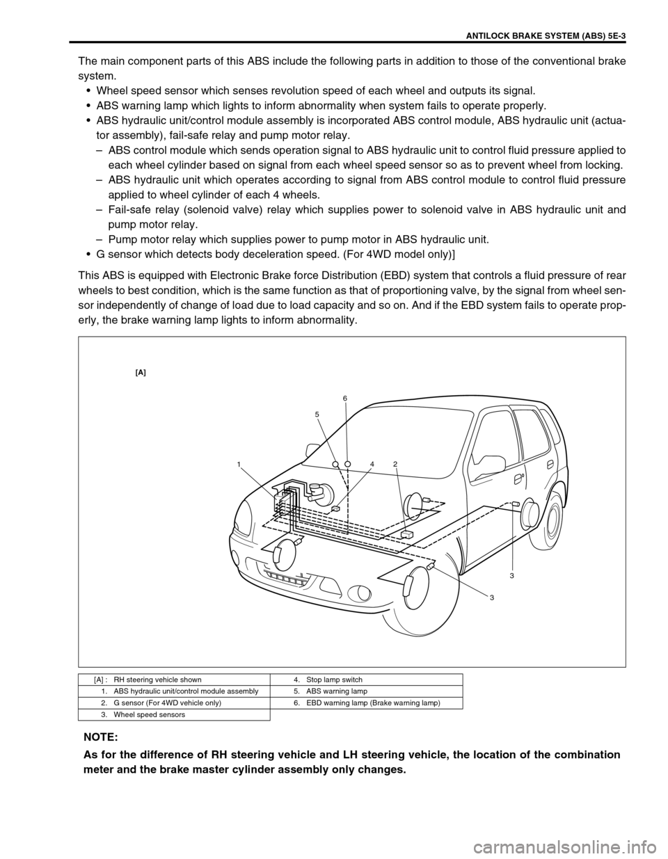
The main component parts of this ABS include the following parts in addition to those of the conventional brake
system.
Wheel speed sensor which senses revolution speed of each wheel and outputs its signal.
ABS warning lamp which lights to inform abnormality when system fails to operate properly.
ABS hydraulic unit/control module assembly is incorporated ABS control module, ABS hydraulic unit (actua-
tor assembly), fail-safe relay and pump motor relay.
–ABS control module which sends operation signal to ABS hydraulic unit to control fluid pressure applied to
each wheel cylinder based on signal from each wheel speed sensor so as to prevent wheel from locking.
–ABS hydraulic unit which operates according to signal from ABS control module to control fluid pressure
applied to wheel cylinder of each 4 wheels.
–Fail-safe relay (solenoid valve) relay which supplies power to solenoid valve in ABS hydraulic unit and
pump motor relay.
–Pump motor relay which supplies power to pump motor in ABS hydraulic unit.
G sensor which detects body deceleration speed. (For 4WD model only)]
This ABS is equipped with Electronic Brake force Distribution (EBD) system that controls a fluid pressure of rear
wheels to best condition, which is the same function as that of proportioning valve, by the signal from wheel sen-
sor independently of change of load due to load capacity and so on. And if the EBD system fails to operate prop-
erly, the brake warning lamp lights to inform abnormality.
[A] : RH steering vehicle shown 4. Stop lamp switch
1. ABS hydraulic unit/control module assembly 5. ABS warning lamp
2. G sensor (For 4WD vehicle only) 6. EBD warning lamp (Brake warning lamp)
3. Wheel speed sensors
156
2 4
33
[A]
NOTE:
As for the difference of RH steering vehicle and LH steering vehicle, the location of the combination
meter and the brake master cylinder assembly only changes.