Torque SUZUKI SWIFT 2000 1.G RG413 Service User Guide
[x] Cancel search | Manufacturer: SUZUKI, Model Year: 2000, Model line: SWIFT, Model: SUZUKI SWIFT 2000 1.GPages: 698, PDF Size: 16.01 MB
Page 46 of 698
MAINTENANCE AND LUBRICATION 0B-17
MANUAL TRANSMISSION OIL
INSPECTION
1) Inspect transmission case for evidence of oil leakage.
Repair leaky point if any.
2) Make sure that vehicle is placed level for oil level check.
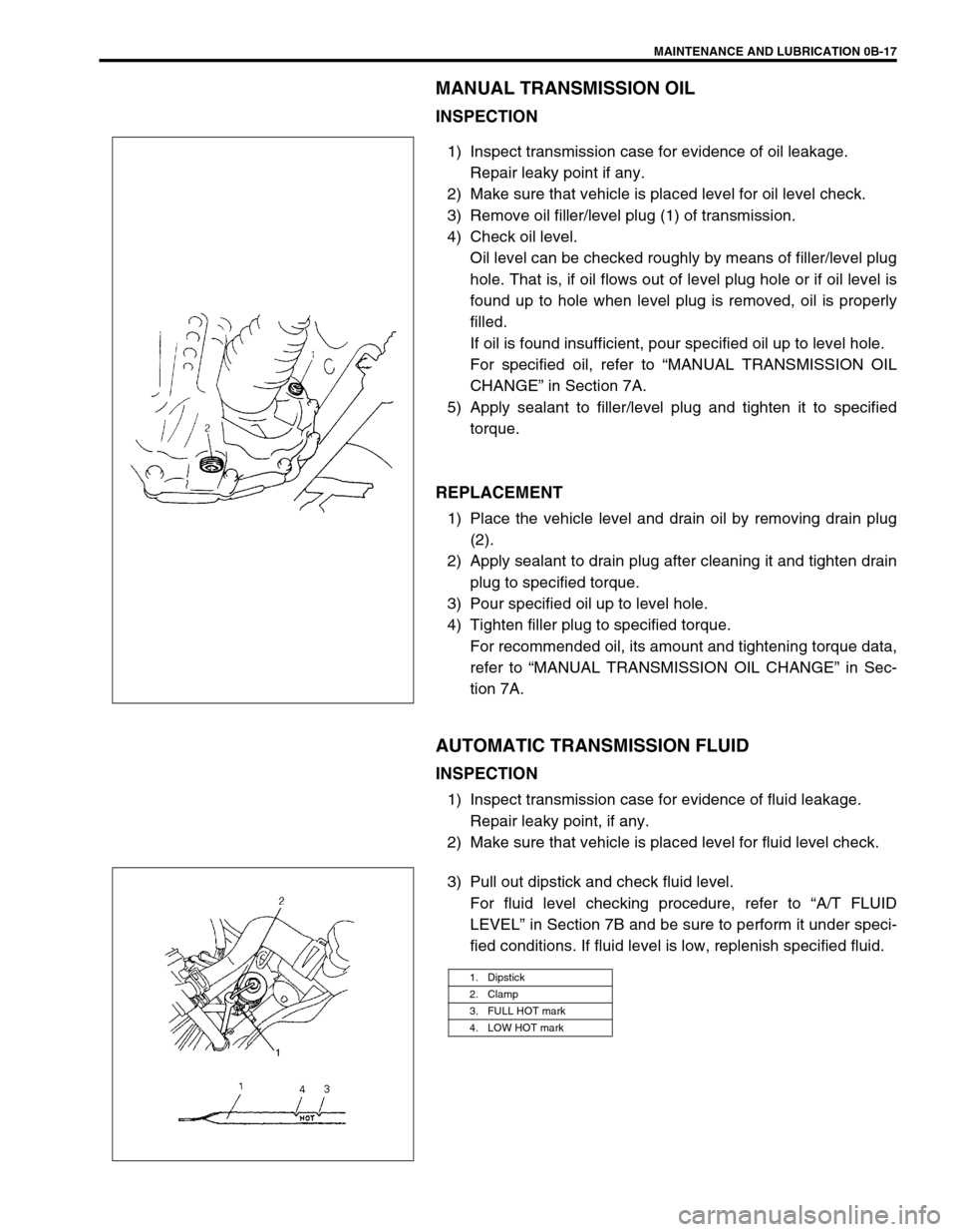
3) Remove oil filler/level plug (1) of transmission.
4) Check oil level.
Oil level can be checked roughly by means of filler/level plug
hole. That is, if oil flows out of level plug hole or if oil level is
found up to hole when level plug is removed, oil is properly
filled.
If oil is found insufficient, pour specified oil up to level hole.
For specified oil, refer to “MANUAL TRANSMISSION OIL
CHANGE” in Section 7A.
5) Apply sealant to filler/level plug and tighten it to specified
torque.
REPLACEMENT
1) Place the vehicle level and drain oil by removing drain plug
(2).
2) Apply sealant to drain plug after cleaning it and tighten drain
plug to specified torque.
3) Pour specified oil up to level hole.
4) Tighten filler plug to specified torque.
For recommended oil, its amount and tightening torque data,
refer to “MANUAL TRANSMISSION OIL CHANGE” in Sec-
tion 7A.
AUTOMATIC TRANSMISSION FLUID
INSPECTION
1) Inspect transmission case for evidence of fluid leakage.
Repair leaky point, if any.
2) Make sure that vehicle is placed level for fluid level check.
3) Pull out dipstick and check fluid level.
For fluid level checking procedure, refer to “A/T FLUID
LEVEL” in Section 7B and be sure to perform it under speci-
fied conditions. If fluid level is low, replenish specified fluid.
1. Dipstick
2. Clamp
3. FULL HOT mark
4. LOW HOT mark
Page 47 of 698
0B-18 MAINTENANCE AND LUBRICATION
REPLACEMENT
1) Inspect transmission case for evidence of fluid leakage.
Repair leaky point, if any.
2) Make sure that vehicle is placed level for fluid level check.
3) Change fluid. For its procedure, refer to “CHANGING A/T
FLUID” in Section 7B.
TRANSFER OIL (4WD) AND REAR DIFFERENTIAL
OIL (4WD)
INSPECTION
1) Check transfer case or differential for evidence of oil leak-
age.
Repair leaky point if any.
2) Make sure that vehicle is placed level for oil level check.
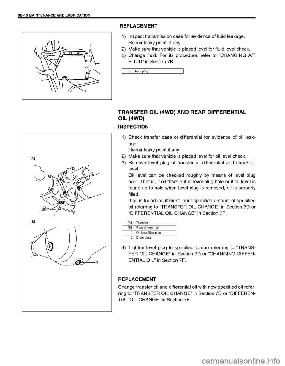
3) Remove level plug of transfer or differential and check oil
level.
Oil level can be checked roughly by means of level plug
hole. That is, if oil flows out of level plug hole or if oil level is
found up to hole when level plug is removed, oil is properly
filled.
If oil is found insufficient, pour specified amount of specified
oil referring to “TRANSFER OIL CHANGE” in Section 7D or
“DIFFERENTIAL OIL CHANGE” in Section 7F.
4) Tighten level plug to specified torque referring to “TRANS-
FER OIL CHANGE” in Section 7D or “CHANGING DIFFER-
ENTIAL OIL” in Section 7F.
REPLACEMENT
Change transfer oil and differential oil with new specified oil refer-
ring to “TRANSFER OIL CHANGE” in Section 7D or “DIFFEREN-
TIAL OIL CHANGE” in Section 7F.
1. Drain plug
[A] : Transfer
[B] : Rear differential
1. Oil level/filler plug
2. Drain plug
Page 92 of 698
AIR CONDITIONING (OPTIONAL) 1B-27
ON-VEHICLE SERVICE
SERVICE PRECAUTION
When servicing air conditioning system, note the following instructions.
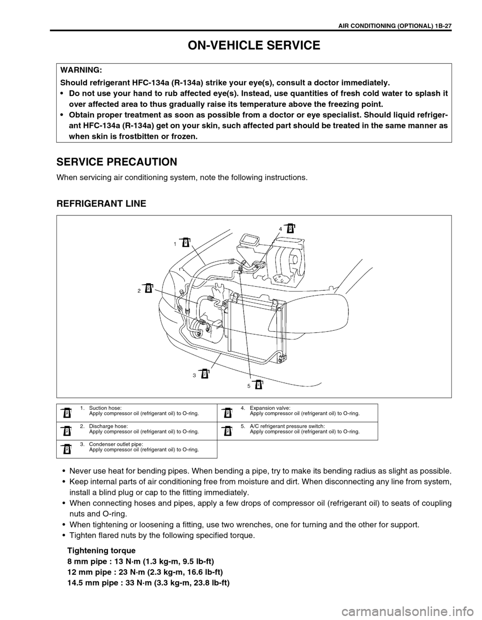
REFRIGERANT LINE
Never use heat for bending pipes. When bending a pipe, try to make its bending radius as slight as possible.
Keep internal parts of air conditioning free from moisture and dirt. When disconnecting any line from system,
install a blind plug or cap to the fitting immediately.
When connecting hoses and pipes, apply a few drops of compressor oil (refrigerant oil) to seats of coupling
nuts and O-ring.
When tightening or loosening a fitting, use two wrenches, one for turning and the other for support.
Tighten flared nuts by the following specified torque.
Tightening torque
8 mm pipe : 13 N·m (1.3 kg-m, 9.5 lb-ft)
12 mm pipe : 23 N·m (2.3 kg-m, 16.6 lb-ft)
14.5 mm pipe : 33 N·m (3.3 kg-m, 23.8 lb-ft) WARNING:
Should refrigerant HFC-134a (R-134a) strike your eye(s), consult a doctor immediately.
Do not use your hand to rub affected eye(s). Instead, use quantities of fresh cold water to splash it
over affected area to thus gradually raise its temperature above the freezing point.
Obtain proper treatment as soon as possible from a doctor or eye specialist. Should liquid refriger-
ant HFC-134a (R-134a) get on your skin, such affected part should be treated in the same manner as
when skin is frostbitten or frozen.
1. Suction hose:
Apply compressor oil (refrigerant oil) to O-ring.4. Expansion valve:
Apply compressor oil (refrigerant oil) to O-ring.
2. Discharge hose:
Apply compressor oil (refrigerant oil) to O-ring.5. A/C refrigerant pressure switch:
Apply compressor oil (refrigerant oil) to O-ring.
3. Condenser outlet pipe:
Apply compressor oil (refrigerant oil) to O-ring.
Page 96 of 698
AIR CONDITIONING (OPTIONAL) 1B-31
Tighten receiver/dryer cap to specified torque
Tightening torque
Receiver / dryer cap : 13 N·m (1.3 kg-m, 9.5 lb-ft)
Replenish specified amount of compressor oil to compressor
suction side by referring to “REPLENISHING COMPRES-
SOR OIL” in this section.
RADIATOR/CONDENSER COOLING FAN
MOTOR
REMOVAL AND INSTALLATION
For details, refer to “RADIATOR” in Section 6B.
INSPECTION
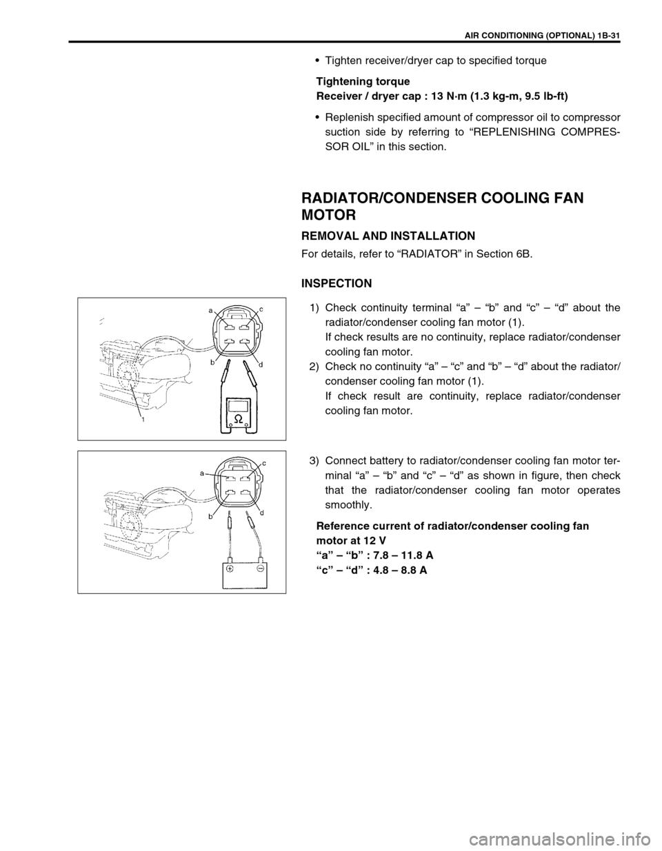
1) Check continuity terminal “a” – “b” and “c” – “d” about the
radiator/condenser cooling fan motor (1).
If check results are no continuity, replace radiator/condenser
cooling fan motor.
2) Check no continuity “a” – “c” and “b” – “d” about the radiator/
condenser cooling fan motor (1).
If check result are continuity, replace radiator/condenser
cooling fan motor.
3) Connect battery to radiator/condenser cooling fan motor ter-
minal “a” – “b” and “c” – “d” as shown in figure, then check
that the radiator/condenser cooling fan motor operates
smoothly.
Reference current of radiator/condenser cooling fan
motor at 12 V
“a” – “b” : 7.8 – 11.8 A
“c” – “d” : 4.8 – 8.8 A
Page 100 of 698
AIR CONDITIONING (OPTIONAL) 1B-35
A/C REFRIGERANT PRESSURE SWITCH
INSPECTION
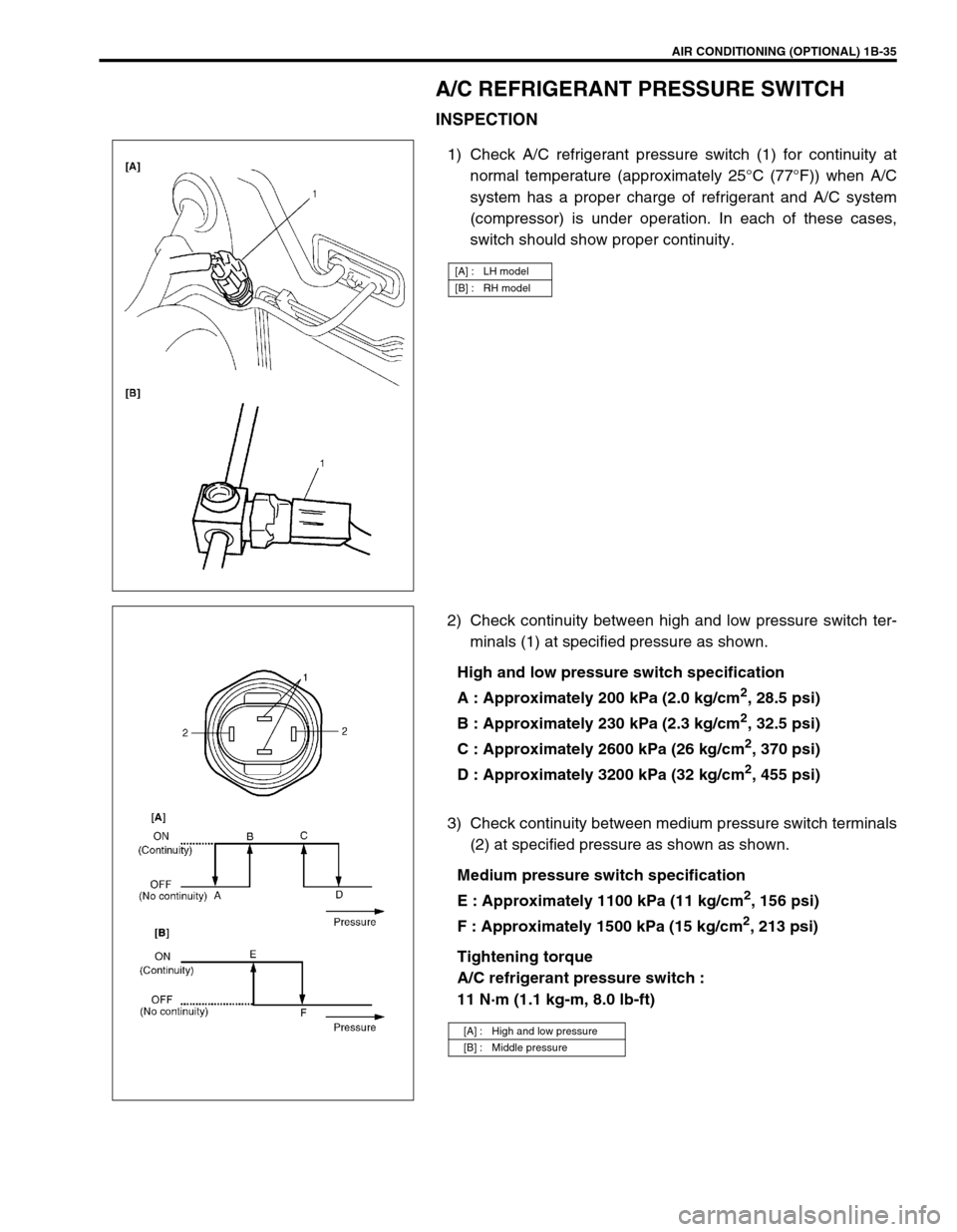
1) Check A/C refrigerant pressure switch (1) for continuity at
normal temperature (approximately 25°C (77°F)) when A/C
system has a proper charge of refrigerant and A/C system
(compressor) is under operation. In each of these cases,
switch should show proper continuity.
2) Check continuity between high and low pressure switch ter-
minals (1) at specified pressure as shown.
High and low pressure switch specification
A : Approximately 200 kPa (2.0 kg/cm
2, 28.5 psi)
B : Approximately 230 kPa (2.3 kg/cm
2, 32.5 psi)
C : Approximately 2600 kPa (26 kg/cm
2, 370 psi)
D : Approximately 3200 kPa (32 kg/cm
2, 455 psi)
3) Check continuity between medium pressure switch terminals
(2) at specified pressure as shown as shown.
Medium pressure switch specification
E : Approximately 1100 kPa (11 kg/cm
2, 156 psi)
F : Approximately 1500 kPa (15 kg/cm
2, 213 psi)
Tightening torque
A/C refrigerant pressure switch :
11 N·m (1.1 kg-m, 8.0 lb-ft)
[A] : LH model
[B] : RH model
[A] : High and low pressure
[B] : Middle pressure
Page 103 of 698
1B-38 AIR CONDITIONING (OPTIONAL)
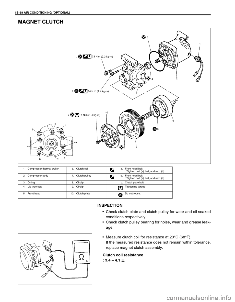
MAGNET CLUTCH
INSPECTION
Check clutch plate and clutch pulley for wear and oil soaked
conditions respectively.
Check clutch pulley bearing for noise, wear and grease leak-
age.
Measure clutch coil for resistance at 20°C (68°F).
If the measured resistance does not remain within tolerance,
replace magnet clutch assembly.
Clutch coil resistance
: 3.4 – 4.1
Ω
ΩΩ Ω
1. Compressor thermal switch 6. Clutch coil a. Front head bolt
: Tighten bolt (a) first, and next (b)
2. Compressor body 7. Clutch pulley b. Front head bolt
: Tighten bolt (a) first, and next (b)
3. O-ring 8. Circlip c. Clutch plate bolt
4. Lip type seal 9. Circlip Tightening torque
5. Front head 10. Clutch plate Do not reuse.
Page 106 of 698
AIR CONDITIONING (OPTIONAL) 1B-41
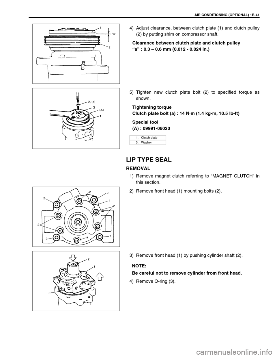
4) Adjust clearance, between clutch plate (1) and clutch pulley
(2) by putting shim on compressor shaft.
Clearance between clutch plate and clutch pulley
“a” : 0.3 – 0.6 mm (0.012 - 0.024 in.)
5) Tighten new clutch plate bolt (2) to specified torque as
shown.
Tightening torque
Clutch plate bolt (a) : 14 N·m (1.4 kg-m, 10.5 lb-ft)
Special tool
(A) : 09991-06020
LIP TYPE SEAL
REMOVAL
1) Remove magnet clutch referring to “MAGNET CLUTCH” in
this section.
2) Remove front head (1) mounting bolts (2).
3) Remove front head (1) by pushing cylinder shaft (2).
4) Remove O-ring (3).
1. Clutch plate
3. Washer
NOTE:
Be careful not to remove cylinder from front head.
Page 108 of 698
AIR CONDITIONING (OPTIONAL) 1B-43
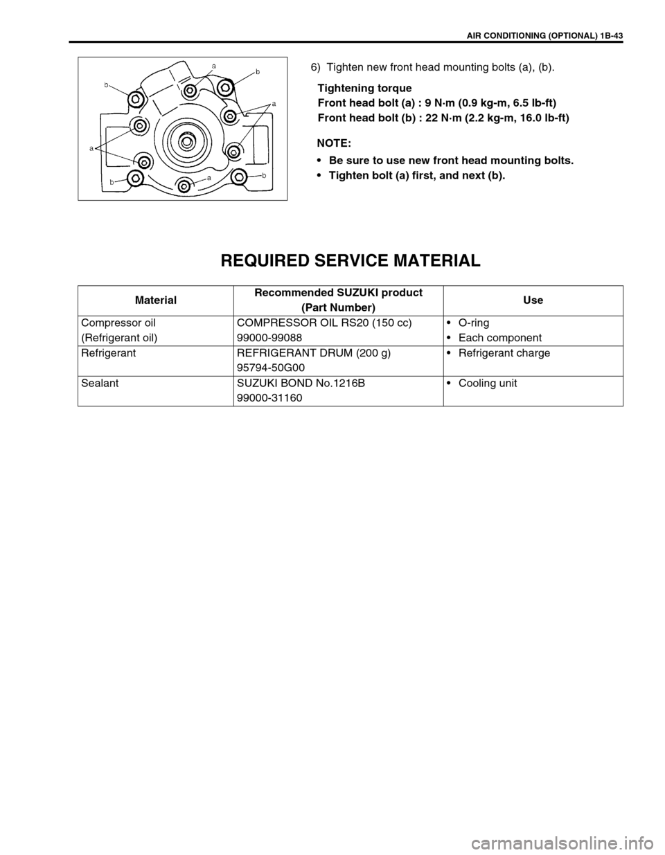
6) Tighten new front head mounting bolts (a), (b).
Tightening torque
Front head bolt (a) : 9 N·m (0.9 kg-m, 6.5 lb-ft)
Front head bolt (b) : 22 N·m (2.2 kg-m, 16.0 lb-ft)
REQUIRED SERVICE MATERIAL
NOTE:
Be sure to use new front head mounting bolts.
Tighten bolt (a) first, and next (b).
MaterialRecommended SUZUKI product
(Part Number)Use
Compressor oil
(Refrigerant oil)COMPRESSOR OIL RS20 (150 cc)
99000-99088O-ring
Each component
Refrigerant REFRIGERANT DRUM (200 g)
95794-50G00Refrigerant charge
Sealant SUZUKI BOND No.1216B
99000-31160Cooling unit
Page 112 of 698
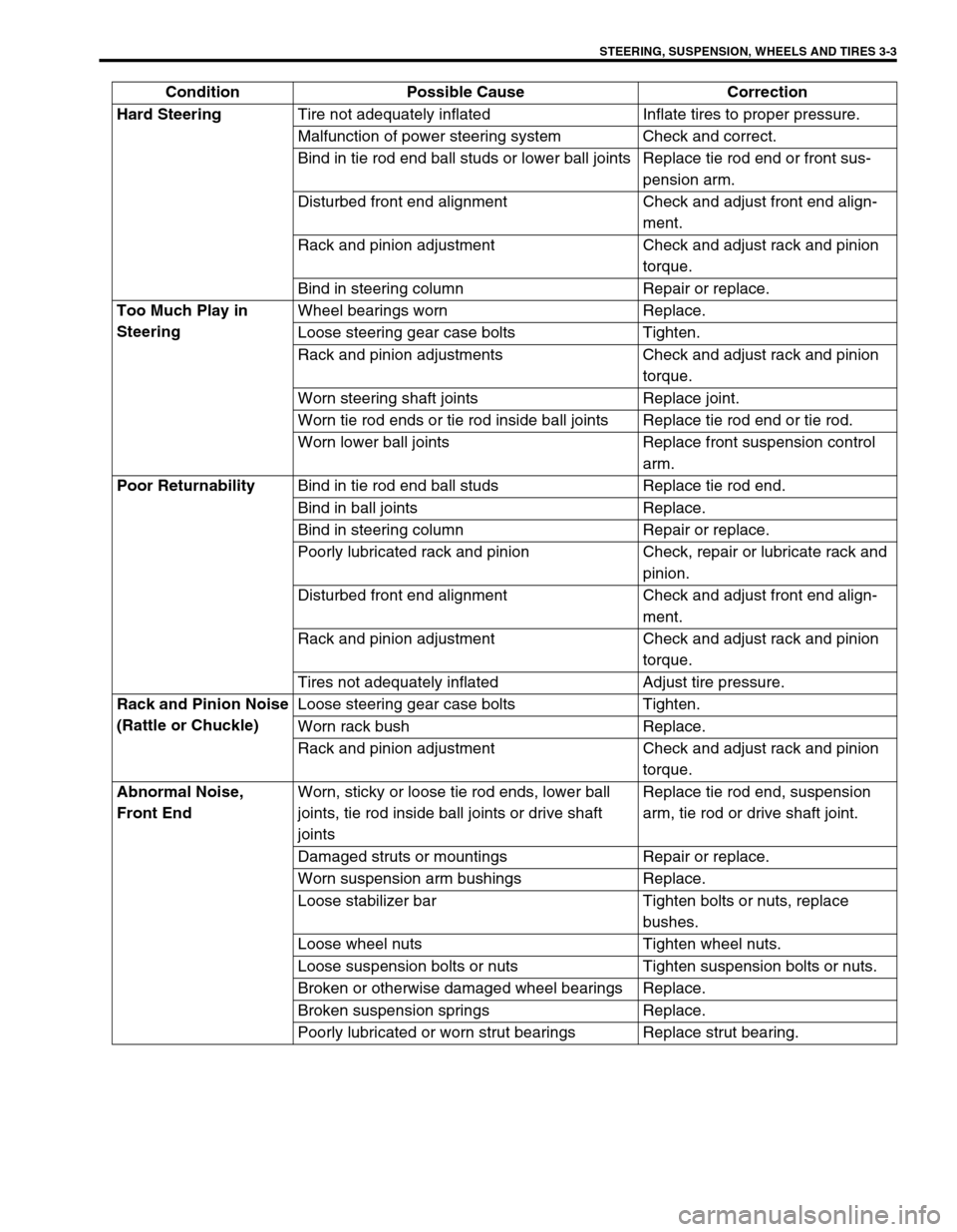
STEERING, SUSPENSION, WHEELS AND TIRES 3-3
Hard Steering
Tire not adequately inflated Inflate tires to proper pressure.
Malfunction of power steering system Check and correct.
Bind in tie rod end ball studs or lower ball joints Replace tie rod end or front sus-
pension arm.
Disturbed front end alignment Check and adjust front end align-
ment.
Rack and pinion adjustment Check and adjust rack and pinion
torque.
Bind in steering column Repair or replace.
Too Much Play in
SteeringWheel bearings worn Replace.
Loose steering gear case bolts Tighten.
Rack and pinion adjustments Check and adjust rack and pinion
torque.
Worn steering shaft joints Replace joint.
Worn tie rod ends or tie rod inside ball joints Replace tie rod end or tie rod.
Worn lower ball joints Replace front suspension control
arm.
Poor Returnability
Bind in tie rod end ball studs Replace tie rod end.
Bind in ball joints Replace.
Bind in steering column Repair or replace.
Poorly lubricated rack and pinion Check, repair or lubricate rack and
pinion.
Disturbed front end alignment Check and adjust front end align-
ment.
Rack and pinion adjustment Check and adjust rack and pinion
torque.
Tires not adequately inflated Adjust tire pressure.
Rack and Pinion Noise
(Rattle or Chuckle)Loose steering gear case bolts Tighten.
Worn rack bush Replace.
Rack and pinion adjustment Check and adjust rack and pinion
torque.
Abnormal Noise,
Front EndWorn, sticky or loose tie rod ends, lower ball
joints, tie rod inside ball joints or drive shaft
jointsReplace tie rod end, suspension
arm, tie rod or drive shaft joint.
Damaged struts or mountings Repair or replace.
Worn suspension arm bushings Replace.
Loose stabilizer bar Tighten bolts or nuts, replace
bushes.
Loose wheel nuts Tighten wheel nuts.
Loose suspension bolts or nuts Tighten suspension bolts or nuts.
Broken or otherwise damaged wheel bearings Replace.
Broken suspension springs Replace.
Poorly lubricated or worn strut bearings Replace strut bearing. Condition Possible Cause Correction
Page 113 of 698
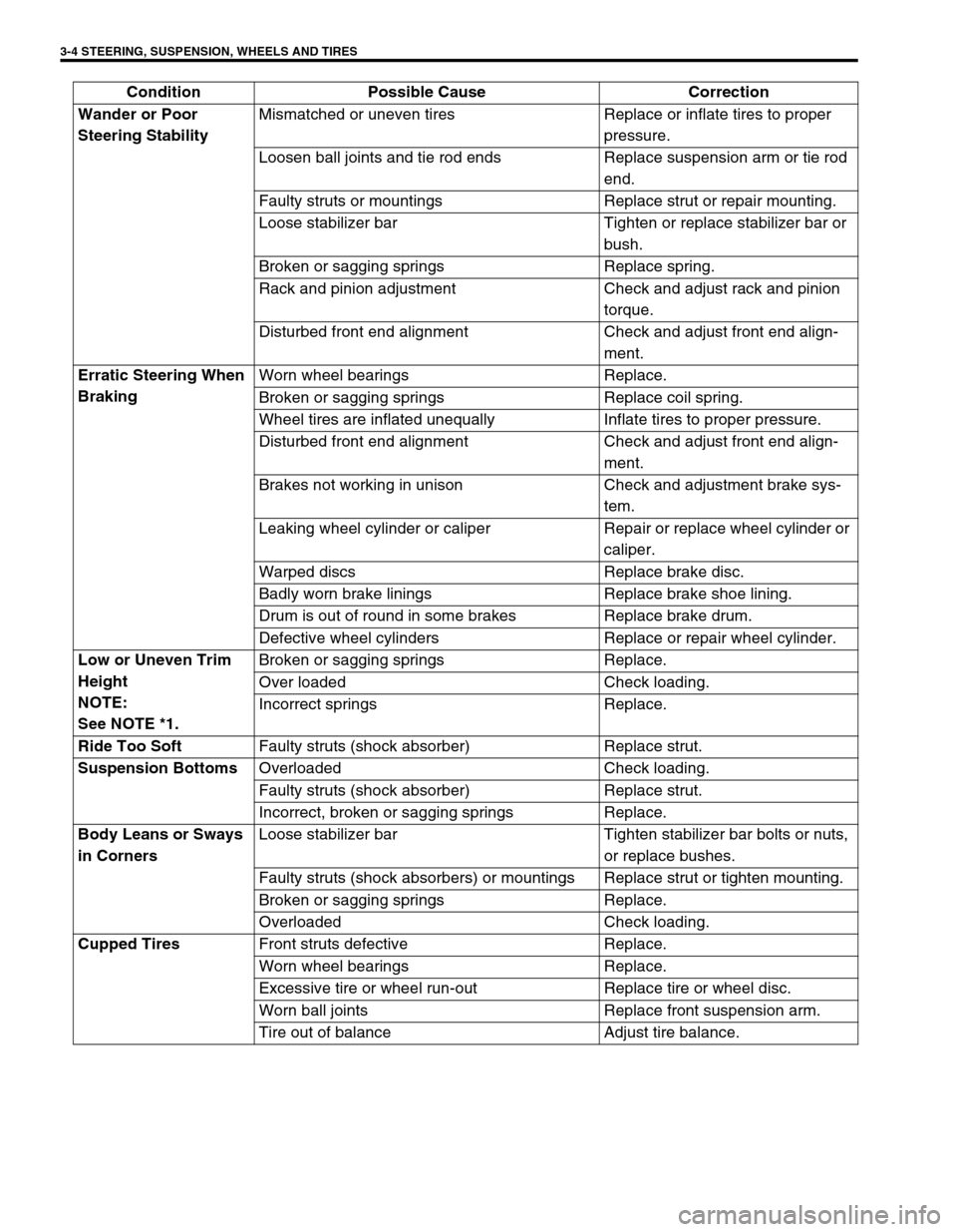
3-4 STEERING, SUSPENSION, WHEELS AND TIRES
Wander or Poor
Steering StabilityMismatched or uneven tires Replace or inflate tires to proper
pressure.
Loosen ball joints and tie rod ends Replace suspension arm or tie rod
end.
Faulty struts or mountings Replace strut or repair mounting.
Loose stabilizer bar Tighten or replace stabilizer bar or
bush.
Broken or sagging springs Replace spring.
Rack and pinion adjustment Check and adjust rack and pinion
torque.
Disturbed front end alignment Check and adjust front end align-
ment.
Erratic Steering When
BrakingWorn wheel bearings Replace.
Broken or sagging springs Replace coil spring.
Wheel tires are inflated unequally Inflate tires to proper pressure.
Disturbed front end alignment Check and adjust front end align-
ment.
Brakes not working in unison Check and adjustment brake sys-
tem.
Leaking wheel cylinder or caliper Repair or replace wheel cylinder or
caliper.
Warped discs Replace brake disc.
Badly worn brake linings Replace brake shoe lining.
Drum is out of round in some brakes Replace brake drum.
Defective wheel cylinders Replace or repair wheel cylinder.
Low or Uneven Trim
Height
NOTE:
See NOTE *1.Broken or sagging springs Replace.
Over loaded Check loading.
Incorrect springs Replace.
Ride Too Soft
Faulty struts (shock absorber) Replace strut.
Suspension Bottoms
Overloaded Check loading.
Faulty struts (shock absorber) Replace strut.
Incorrect, broken or sagging springs Replace.
Body Leans or Sways
in CornersLoose stabilizer bar Tighten stabilizer bar bolts or nuts,
or replace bushes.
Faulty struts (shock absorbers) or mountings Replace strut or tighten mounting.
Broken or sagging springs Replace.
Overloaded Check loading.
Cupped Tires
Front struts defective Replace.
Worn wheel bearings Replace.
Excessive tire or wheel run-out Replace tire or wheel disc.
Worn ball joints Replace front suspension arm.
Tire out of balance Adjust tire balance. Condition Possible Cause Correction