boot SUZUKI SWIFT 2000 1.G RG413 Service User Guide
[x] Cancel search | Manufacturer: SUZUKI, Model Year: 2000, Model line: SWIFT, Model: SUZUKI SWIFT 2000 1.GPages: 698, PDF Size: 16.01 MB
Page 136 of 698
MANUAL RACK AND PINION 3B-15
INSTALLATION
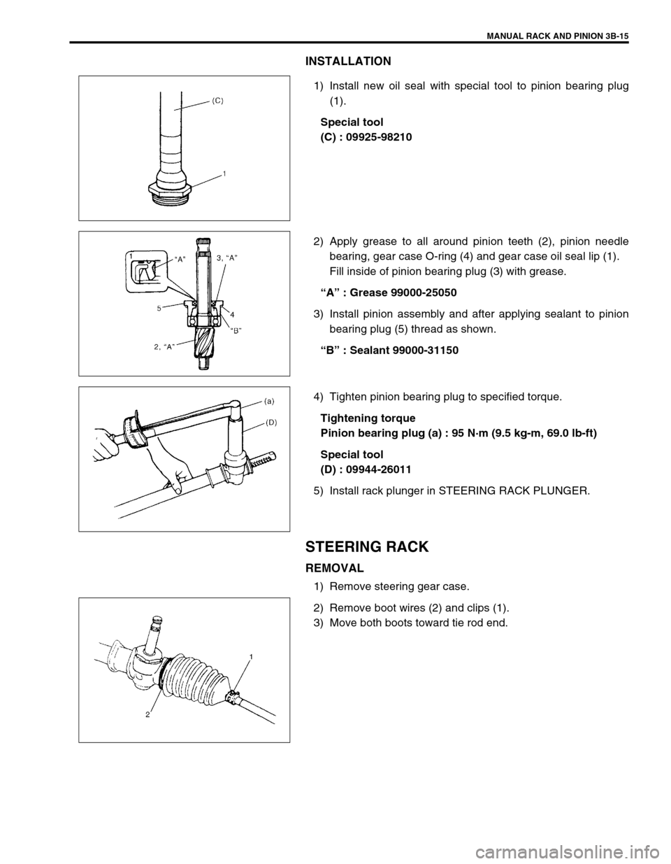
1) Install new oil seal with special tool to pinion bearing plug
(1).
Special tool
(C) : 09925-98210
2) Apply grease to all around pinion teeth (2), pinion needle
bearing, gear case O-ring (4) and gear case oil seal lip (1).
Fill inside of pinion bearing plug (3) with grease.
“A” : Grease 99000-25050
3) Install pinion assembly and after applying sealant to pinion
bearing plug (5) thread as shown.
“B” : Sealant 99000-31150
4) Tighten pinion bearing plug to specified torque.
Tightening torque
Pinion bearing plug (a) : 95 N·m (9.5 kg-m, 69.0 lb-ft)
Special tool
(D) : 09944-26011
5) Install rack plunger in STEERING RACK PLUNGER.
STEERING RACK
REMOVAL
1) Remove steering gear case.
2) Remove boot wires (2) and clips (1).
3) Move both boots toward tie rod end.
Page 138 of 698
MANUAL RACK AND PINION 3B-17
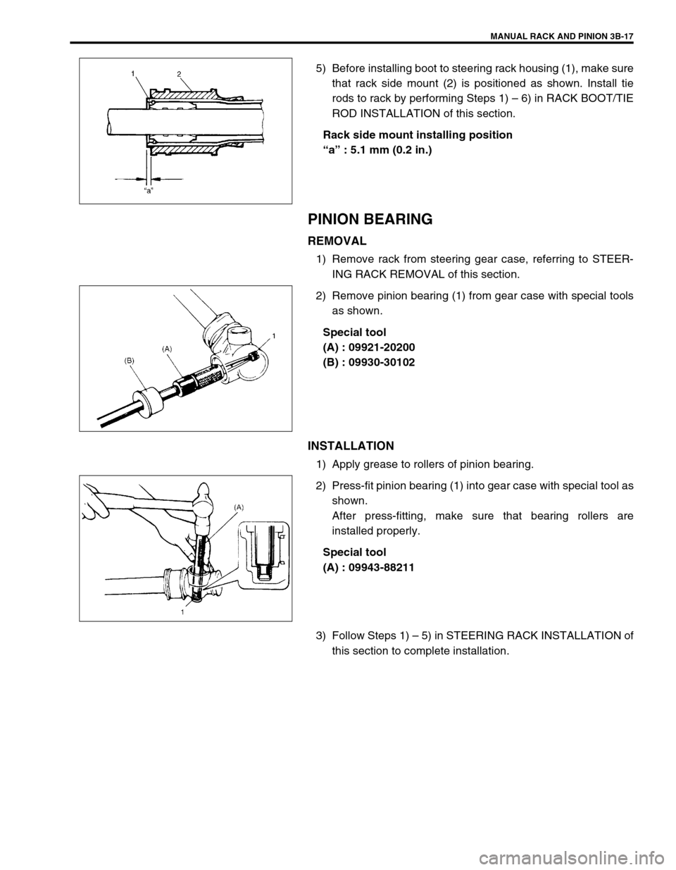
5) Before installing boot to steering rack housing (1), make sure
that rack side mount (2) is positioned as shown. Install tie
rods to rack by performing Steps 1) – 6) in RACK BOOT/TIE
ROD INSTALLATION of this section.
Rack side mount installing position
“a” : 5.1 mm (0.2 in.)
PINION BEARING
REMOVAL
1) Remove rack from steering gear case, referring to STEER-
ING RACK REMOVAL of this section.
2) Remove pinion bearing (1) from gear case with special tools
as shown.
Special tool
(A) : 09921-20200
(B) : 09930-30102
INSTALLATION
1) Apply grease to rollers of pinion bearing.
2) Press-fit pinion bearing (1) into gear case with special tool as
shown.
After press-fitting, make sure that bearing rollers are
installed properly.
Special tool
(A) : 09943-88211
3) Follow Steps 1) – 5) in STEERING RACK INSTALLATION of
this section to complete installation.
Page 140 of 698
MANUAL RACK AND PINION 3B-19
INSTALLATION
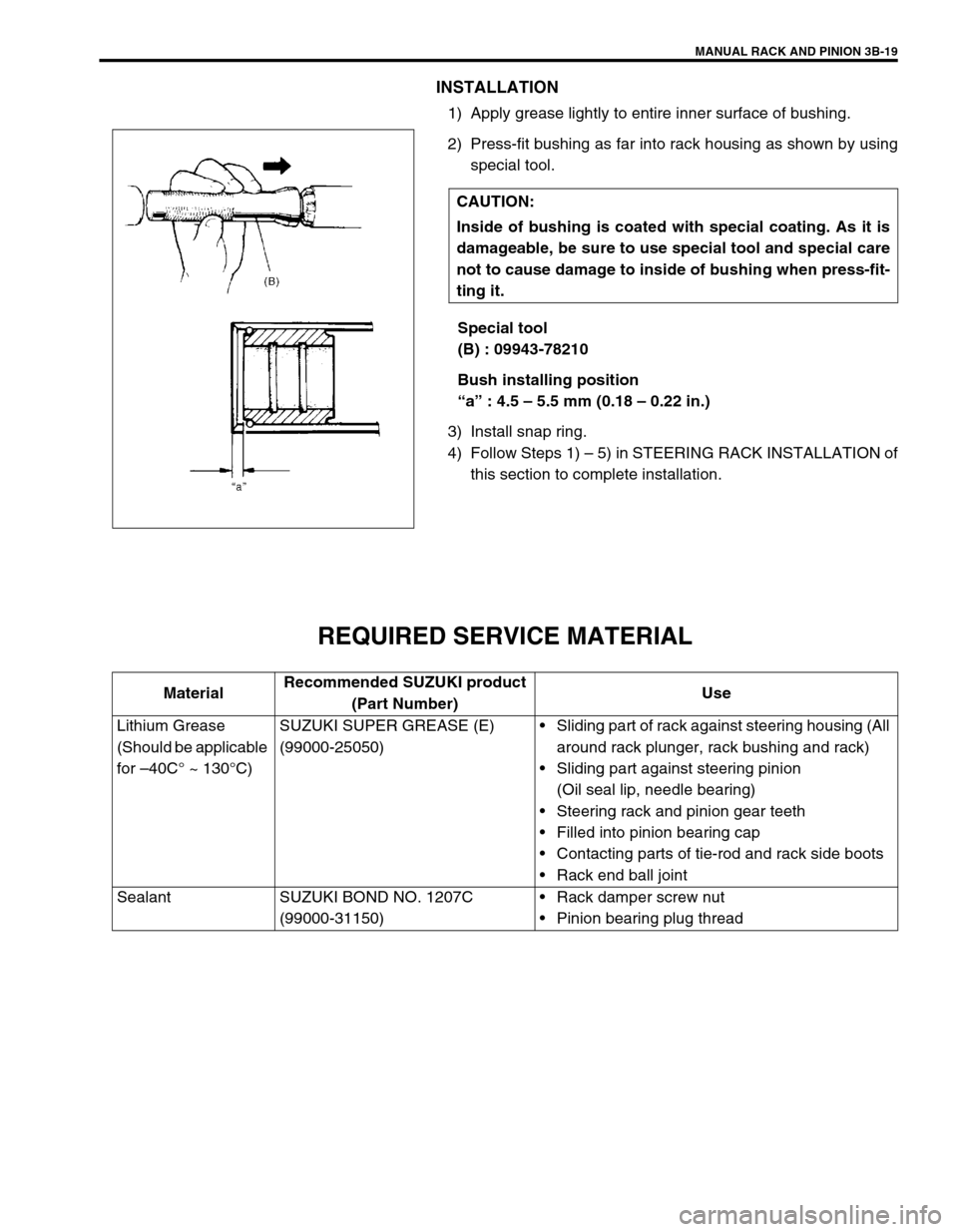
1) Apply grease lightly to entire inner surface of bushing.
2) Press-fit bushing as far into rack housing as shown by using
special tool.
Special tool
(B) : 09943-78210
Bush installing position
“a” : 4.5 – 5.5 mm (0.18 – 0.22 in.)
3) Install snap ring.
4) Follow Steps 1) – 5) in STEERING RACK INSTALLATION of
this section to complete installation.
REQUIRED SERVICE MATERIAL
CAUTION:
Inside of bushing is coated with special coating. As it is
damageable, be sure to use special tool and special care
not to cause damage to inside of bushing when press-fit-
ting it.
MaterialRecommended SUZUKI product
(Part Number)Use
Lithium Grease
(Should be applicable
for –40C° ~ 130°C)SUZUKI SUPER GREASE (E)
(99000-25050)Sliding part of rack against steering housing (All
around rack plunger, rack bushing and rack)
Sliding part against steering pinion
(Oil seal lip, needle bearing)
Steering rack and pinion gear teeth
Filled into pinion bearing cap
Contacting parts of tie-rod and rack side boots
Rack end ball joint
Sealant SUZUKI BOND NO. 1207C
(99000-31150)Rack damper screw nut
Pinion bearing plug thread
Page 254 of 698
FRONT DRIVE SHAFT 4A-1
6F1
6F2
6G
6H
6K
7A
7A1
7B1
7C1
7D
7E
7F
4A
8C
8D
8E
9
10
10A
10B
SECTION 4A
FRONT DRIVE SHAFT
CONTENTS
GENERAL DESCRIPTION .............................. 4A-2
COMPONENT .............................................. 4A-2
DIAGNOSIS ..................................................... 4A-2
DIAGNOSIS TABLE ..................................... 4A-2
DRIVE SHAFT BOOT CHECK ..................... 4A-2ON-VEHICLE SERVICE .................................. 4A-3
DRIVE SHAFT ASSEMBLY ......................... 4A-4
TIGHTENING TORQUE SPECIFICATION.... 4A-16
REQUIRED SERVICE MATERIAL................ 4A-16
SPECIAL TOOL ............................................ 4A-16
Page 255 of 698
4A-2 FRONT DRIVE SHAFT
GENERAL DESCRIPTION
COMPONENT
A constant velocity ball joint is used on the wheel side of front drive shaft. For right side drive shaft of 2WD vehi-
cle, a constant velocity tripod joint on the differential side. For left side drive shaft of every type vehicles and
right side drive shaft of 4WD vehicle, a constant velocity double offset joint is used on the differential or transfer
side. The drive shaft can slide through the tripod joint or the double offset joint in the extension/contraction direc-
tion.
DIAGNOSIS
DIAGNOSIS TABLE
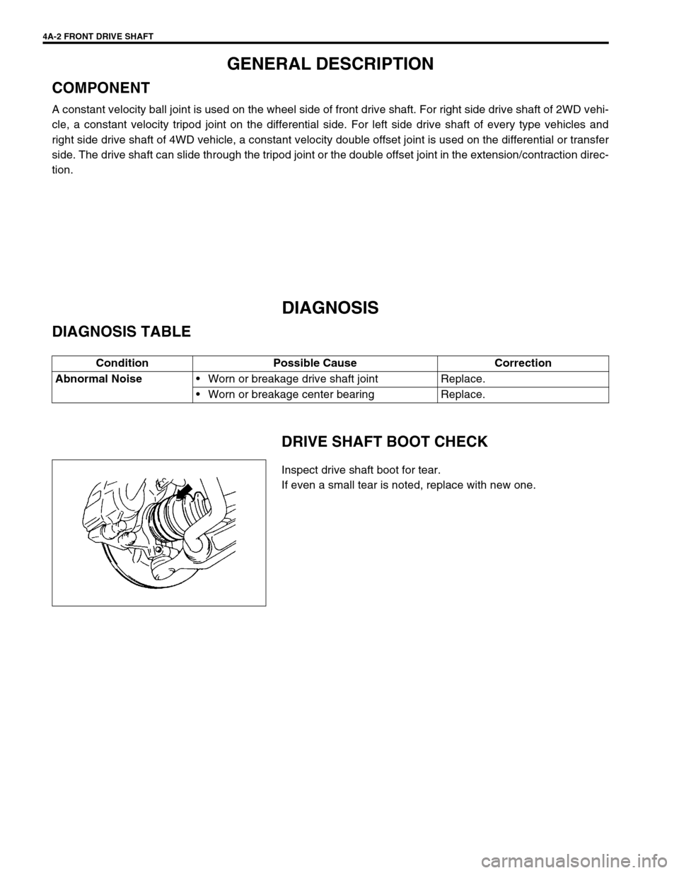
DRIVE SHAFT BOOT CHECK
Inspect drive shaft boot for tear.
If even a small tear is noted, replace with new one. Condition Possible Cause Correction
Abnormal Noise
Worn or breakage drive shaft joint Replace.
Worn or breakage center bearing Replace.
Page 256 of 698
FRONT DRIVE SHAFT 4A-3
ON-VEHICLE SERVICE
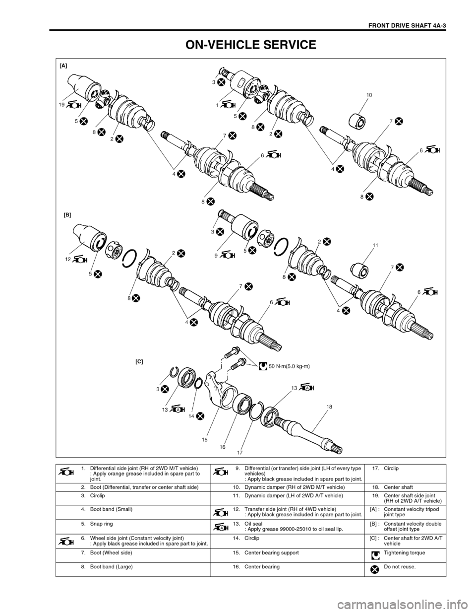
1. Differential side joint (RH of 2WD M/T vehicle)
: Apply orange grease included in spare part to
joint.9. Differential (or transfer) side joint (LH of every type
vehicles)
: Apply black grease included in spare part to joint.17. Circlip
2. Boot (Differential, transfer or center shaft side) 10. Dynamic damper (RH of 2WD M/T vehicle) 18. Center shaft
3. Circlip 11. Dynamic damper (LH of 2WD A/T vehicle) 19. Center shaft side joint
(RH of 2WD A/T vehicle)
4. Boot band (Small) 12. Transfer side joint (RH of 4WD vehicle)
: Apply black grease included in spare part to joint.[A] : Constant velocity tripod
joint type
5. Snap ring 13. Oil seal
: Apply grease 99000-25010 to oil seal lip.[B] : Constant velocity double
offset joint type
6. Wheel side joint (Constant velocity joint)
: Apply black grease included in spare part to joint.14. Circlip [C] : Center shaft for 2WD A/T
vehicle
7. Boot (Wheel side) 15. Center bearing support Tightening torque
8. Boot band (Large) 16. Center bearing Do not reuse.
Page 258 of 698
FRONT DRIVE SHAFT 4A-5
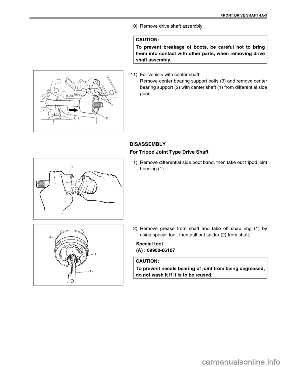
10) Remove drive shaft assembly.
11) For vehicle with center shaft
Remove center bearing support bolts (3) and remove center
bearing support (2) with center shaft (1) from differential side
gear.
DISASSEMBLY
For Tripod Joint Type Drive Shaft
1) Remove differential side boot band, then take out tripod joint
housing (1).
2) Remove grease from shaft and take off snap ring (1) by
using special tool, then pull out spider (2) from shaft.
Special tool
(A) : 09900-06107 CAUTION:
To prevent breakage of boots, be careful not to bring
them into contact with other parts, when removing drive
shaft assembly.
3
2
1
CAUTION:
To prevent needle bearing of joint from being degreased,
do not wash it if it is to be reused.
Page 259 of 698
4A-6 FRONT DRIVE SHAFT
3) Remove boot band, then pull out differential side boot from
shaft.
4) Pull out damper through shaft. (if equipped)
5) Undo boot bands of wheel side joint boot, then pull out boot
through shaft.
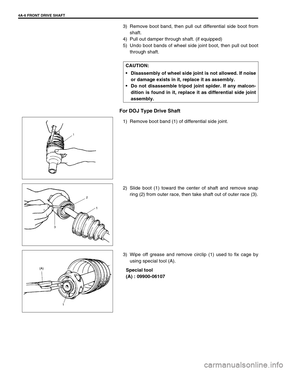
For DOJ Type Drive Shaft
1) Remove boot band (1) of differential side joint.
2) Slide boot (1) toward the center of shaft and remove snap
ring (2) from outer race, then take shaft out of outer race (3).
3) Wipe off grease and remove circlip (1) used to fix cage by
using special tool (A).
Special tool
(A) : 09900-06107 CAUTION:
Disassembly of wheel side joint is not allowed. If noise
or damage exists in it, replace it as assembly.
Do not disassemble tripod joint spider. If any malcon-
dition is found in it, replace it as differential side joint
assembly.
Page 260 of 698
FRONT DRIVE SHAFT 4A-7
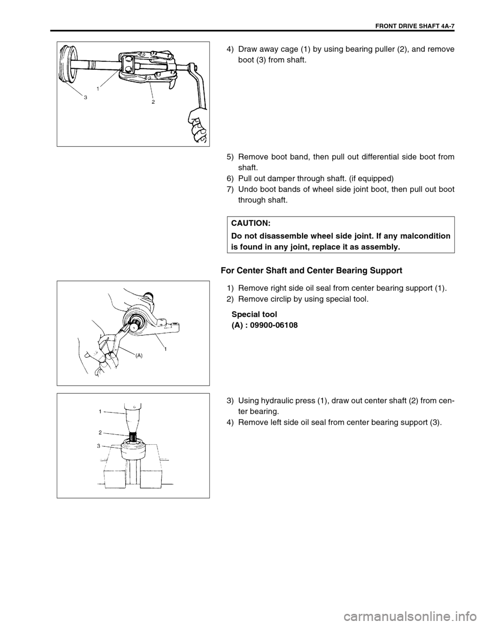
4) Draw away cage (1) by using bearing puller (2), and remove
boot (3) from shaft.
5) Remove boot band, then pull out differential side boot from
shaft.
6) Pull out damper through shaft. (if equipped)
7) Undo boot bands of wheel side joint boot, then pull out boot
through shaft.
For Center Shaft and Center Bearing Support
1) Remove right side oil seal from center bearing support (1).
2) Remove circlip by using special tool.
Special tool
(A) : 09900-06108
3) Using hydraulic press (1), draw out center shaft (2) from cen-
ter bearing.
4) Remove left side oil seal from center bearing support (3).
CAUTION:
Do not disassemble wheel side joint. If any malcondition
is found in any joint, replace it as assembly.
Page 261 of 698
4A-8 FRONT DRIVE SHAFT
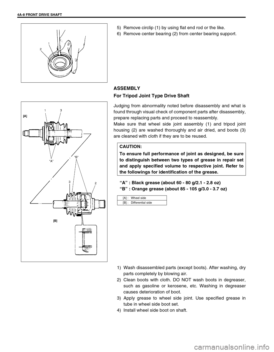
5) Remove circlip (1) by using flat end rod or the like.
6) Remove center bearing (2) from center bearing support.
ASSEMBLY
For Tripod Joint Type Drive Shaft
Judging from abnormality noted before disassembly and what is
found through visual check of component parts after disassembly,
prepare replacing parts and proceed to reassembly.
Make sure that wheel side joint assembly (1) and tripod joint
housing (2) are washed thoroughly and air dried, and boots (3)
are cleaned with cloth if they are to be reused.
“A” : Black grease (about 60 - 80 g/2.1 - 2.8 oz)
“B” : Orange grease (about 85 - 105 g/3.0 - 3.7 oz)
1) Wash disassembled parts (except boots). After washing, dry
parts completely by blowing air.
2) Clean boots with cloth. DO NOT wash boots in degreaser,
such as gasoline or kerosene, etc. Washing in degreaser
causes deterioration of boot.
3) Apply grease to wheel side joint. Use specified grease in
tube in wheel side boot set.
4) Install wheel side boot on shaft.
CAUTION:
To ensure full performance of joint as designed, be sure
to distinguish between two types of grease in repair set
and apply specified volume to respective joint. Refer to
the followings for identification of the grease.
[A] : Wheel side
[B] : Differential side