heating SUZUKI SWIFT 2000 1.G RG413 Service User Guide
[x] Cancel search | Manufacturer: SUZUKI, Model Year: 2000, Model line: SWIFT, Model: SUZUKI SWIFT 2000 1.GPages: 698, PDF Size: 16.01 MB
Page 602 of 698

ENGINE COOLING 6B-13
Check thermostatic movement of wax pellet as follows :
a) Immerse thermostat (1) in water, and heat water gradually.
b) Check that valve starts to open at specific temperature.
Temperature at which valve begins to open
: 80 – 84°C (176 – 183°F)
Temperature at which valve become fully open
: 95 – 97°C (203°F)
Valve lift
: More than 8 mm at 95°C (203°F)
If valve starts to open at a temperature substantially below or
above specific temperature, thermostat unit should be replaced
with a new one. Such a unit, if reused, will bring about overcool-
ing or overheating tendency.
INSTALLATION
Reverse removal procedure for installation noting the following
points.
When positioning thermostat (1) on thermostat case (2), be
sure to position it so that air bleed valve (3) comes at posi-
tion as shown in figure.
Use new O-rings when installing.
Adjust water pump belt tension referring to WATER PUMP/
GENERATOR DRIVE BELT TENSION INSPECTION AND
ADJUSTMENT in this section.
Adjust A/C compressor belt tension (if equipped) referring to
Section 1B.
Refill cooling system with proper coolant referring to “COOL-
ING SYSTEM REFILL”.
Verify that there is no coolant leakage at each connection.
2. Thermometer
3. Heater
Page 650 of 698

ENGINE AND EMISSION CONTROL SYSTEM 6E1-29
INTAKE AIR TEMPERATURE SENSOR (IAT SENSOR)
REMOVAL
1) Disconnect battery negative cable at battery.
2) Disconnect coupler (1) from IAT sensor.
3) Remove IAT sensor from air cleaner case (2).
INSPECTION
Immerse temperature sensing part of IAT sensor in water (or ice)
and measure resistance between sensor terminals while heating
water gradually.
If measured resistance does not show such characteristic as
shown in left figure, replace IAT sensor.
INSTALLATION
Reverse removal procedure noting the following.
Clean mating surfaces of IAT sensor and air cleaner case.
Connect IAT sensor connector (1) securely.
1
2
1
Page 651 of 698

6E1-30 ENGINE AND EMISSION CONTROL SYSTEM
ENGINE COOLANT TEMPERATURE SENSOR (ECT
SENSOR)
REMOVAL
1) Disconnect battery negative cable at battery.
2) Drain coolant referring to Section 6B.
3) Remove air intake pipe.
4) Disconnect connector from ECT sensor.
5) Remove ECT sensor (1) from thermostat case.
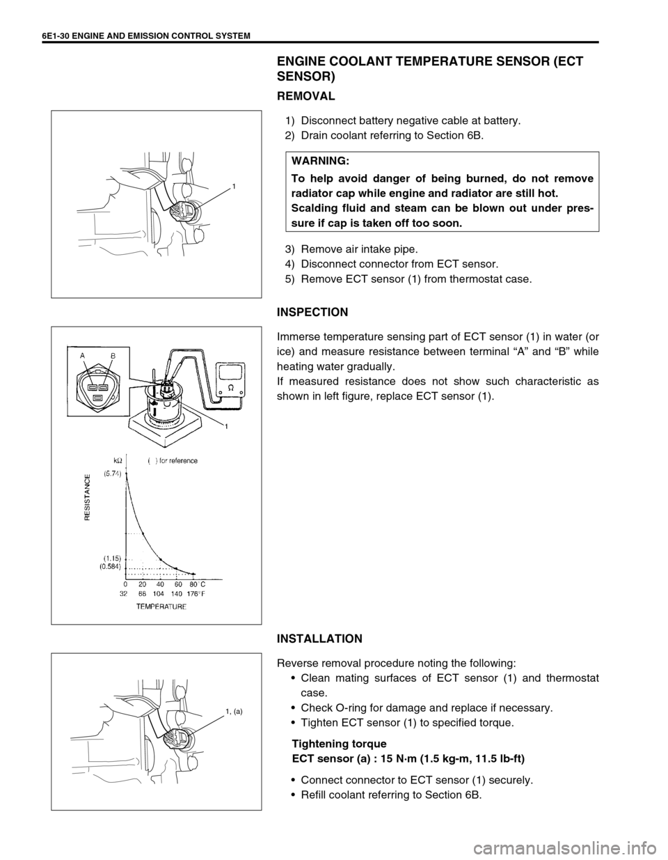
INSPECTION
Immerse temperature sensing part of ECT sensor (1) in water (or
ice) and measure resistance between terminal “A” and “B” while
heating water gradually.
If measured resistance does not show such characteristic as
shown in left figure, replace ECT sensor (1).
INSTALLATION
Reverse removal procedure noting the following:
Clean mating surfaces of ECT sensor (1) and thermostat
case.
Check O-ring for damage and replace if necessary.
Tighten ECT sensor (1) to specified torque.
Tightening torque
ECT sensor (a) : 15 N·m (1.5 kg-m, 11.5 lb-ft)
Connect connector to ECT sensor (1) securely.
Refill coolant referring to Section 6B. WARNING:
To help avoid danger of being burned, do not remove
radiator cap while engine and radiator are still hot.
Scalding fluid and steam can be blown out under pres-
sure if cap is taken off too soon.
1
1, (a)
Page 696 of 698

6K-2 EXHAUST SYSTEM
GENERAL DESCRIPTION
The exhaust system consists of an exhaust manifold, three-way catalytic converter (TWC) in catalyst case,
exhaust pipes, a muffler and seals, gasket and etc.
The three-way catalytic converter is an emission control device added to the exhaust system to lower the levels
of Hydrocarbon (HC), Carbon Monoxide (CO), and Oxides of Nitrogen (NOx) pollutants in the exhaust gas.
MAINTENANCE
At every interval of periodic maintenance service, and when vehi-
cle is raised for other service, check exhaust system as follows:
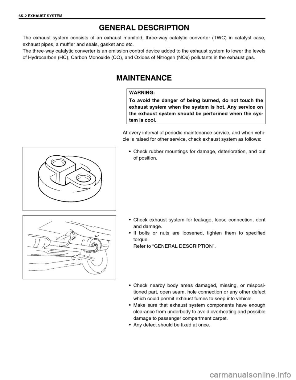
Check rubber mountings for damage, deterioration, and out
of position.
Check exhaust system for leakage, loose connection, dent
and damage.
If bolts or nuts are loosened, tighten them to specified
torque.
Refer to “GENERAL DESCRIPTION”.
Check nearby body areas damaged, missing, or misposi-
tioned part, open seam, hole connection or any other defect
which could permit exhaust fumes to seep into vehicle.
Make sure that exhaust system components have enough
clearance from underbody to avoid overheating and possible
damage to passenger compartment carpet.
Any defect should be fixed at once. WARNING:
To avoid the danger of being burned, do not touch the
exhaust system when the system is hot. Any service on
the exhaust system should be performed when the sys-
tem is cool.