radiator SUZUKI SWIFT 2000 1.G RG413 Service User Guide
[x] Cancel search | Manufacturer: SUZUKI, Model Year: 2000, Model line: SWIFT, Model: SUZUKI SWIFT 2000 1.GPages: 698, PDF Size: 16.01 MB
Page 81 of 698
1B-16 AIR CONDITIONING (OPTIONAL)
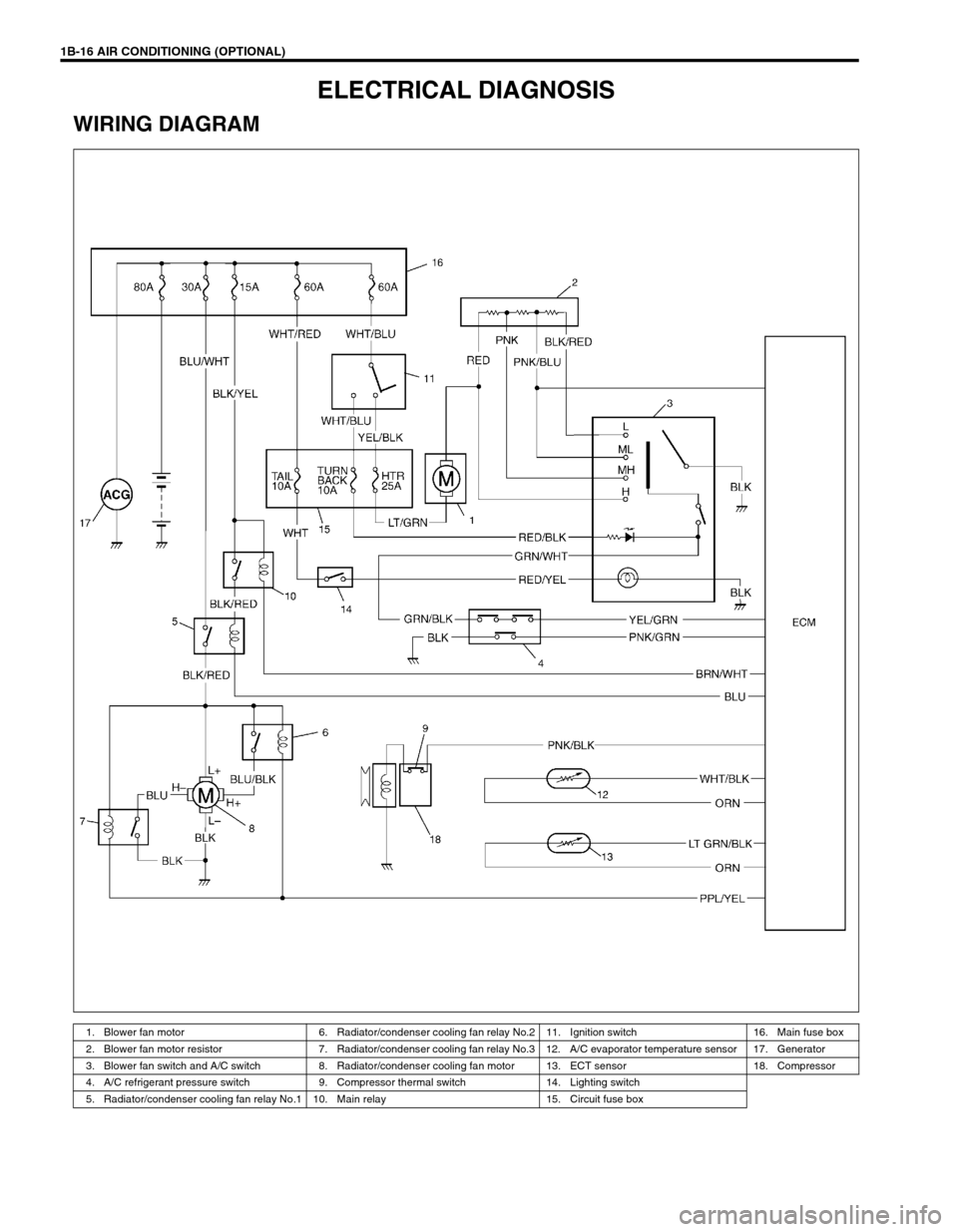
ELECTRICAL DIAGNOSIS
WIRING DIAGRAM
1. Blower fan motor 6. Radiator/condenser cooling fan relay No.2 11. Ignition switch 16. Main fuse box
2. Blower fan motor resistor 7. Radiator/condenser cooling fan relay No.3 12. A/C evaporator temperature sensor 17. Generator
3. Blower fan switch and A/C switch 8. Radiator/condenser cooling fan motor 13. ECT sensor 18. Compressor
4. A/C refrigerant pressure switch 9. Compressor thermal switch 14. Lighting switch
5. Radiator/condenser cooling fan relay No.1 10. Main relay 15. Circuit fuse box
Page 83 of 698
1B-18 AIR CONDITIONING (OPTIONAL)
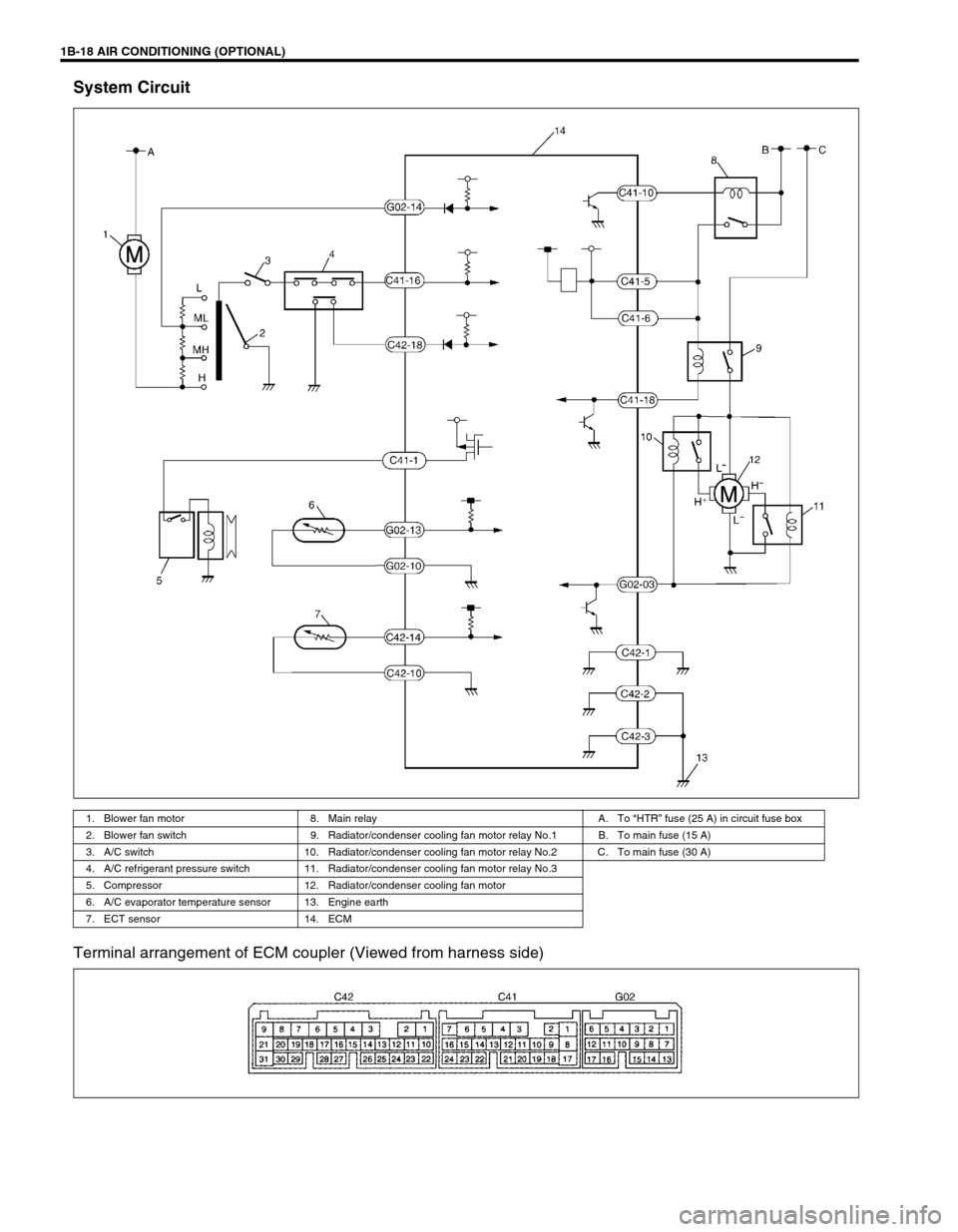
System Circuit
Terminal arrangement of ECM coupler (Viewed from harness side)
1. Blower fan motor 8. Main relay A. To “HTR” fuse (25 A) in circuit fuse box
2. Blower fan switch 9. Radiator/condenser cooling fan motor relay No.1 B. To main fuse (15 A)
3. A/C switch 10. Radiator/condenser cooling fan motor relay No.2 C. To main fuse (30 A)
4. A/C refrigerant pressure switch 11. Radiator/condenser cooling fan motor relay No.3
5. Compressor 12. Radiator/condenser cooling fan motor
6. A/C evaporator temperature sensor 13. Engine earth
7. ECT sensor 14. ECM
Page 84 of 698
AIR CONDITIONING (OPTIONAL) 1B-19
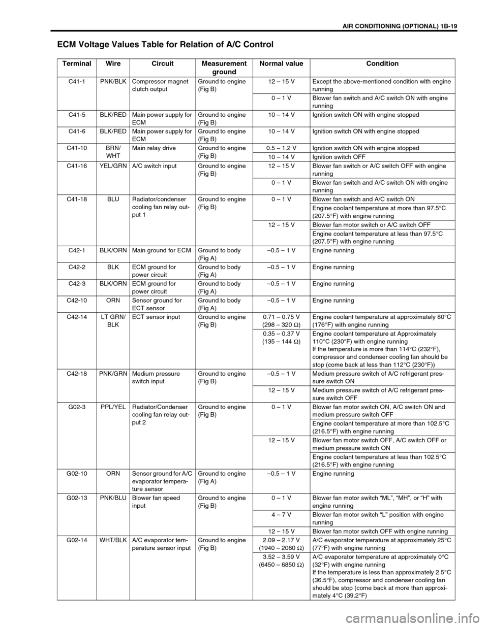
ECM Voltage Values Table for Relation of A/C Control
Terminal Wire Circuit Measurement
groundNormal value Condition
C41-1 PNK/BLK Compressor magnet
clutch outputGround to engine
(Fig B)12 – 15 V Except the above-mentioned condition with engine
running
0 – 1 V Blower fan switch and A/C switch ON with engine
running
C41-5 BLK/RED Main power supply for
ECMGround to engine
(Fig B)10 – 14 V Ignition switch ON with engine stopped
C41-6 BLK/RED Main power supply for
ECMGround to engine
(Fig B)10 – 14 V Ignition switch ON with engine stopped
C41-10 BRN/
WHTMain relay drive Ground to engine
(Fig B)0.5 – 1.2 V Ignition switch ON with engine stopped
10 – 14 V Ignition switch OFF
C41-16 YEL/GRN A/C switch input Ground to engine
(Fig B)12 – 15 V Blower fan switch or A/C switch OFF with engine
running
0 – 1 V Blower fan switch and A/C switch ON with engine
running
C41-18 BLU Radiator/condenser
cooling fan relay out-
put 1Ground to engine
(Fig B)0 – 1 V Blower fan switch and A/C switch ON
Engine coolant temperature at more than 97.5°C
(207.5°F) with engine running
12 – 15 V Blower fan motor switch or A/C switch OFF
Engine coolant temperature at less than 97.5°C
(207.5°F) with engine running
C42-1 BLK/ORN Main ground for ECM Ground to body
(Fig A)–0.5 – 1 V Engine running
C42-2 BLK ECM ground for
power circuitGround to body
(Fig A)–0.5 – 1 V Engine running
C42-3 BLK/ORN ECM ground for
power circuitGround to body
(Fig A)–0.5 – 1 V Engine running
C42-10 ORN Sensor ground for
ECT sensorGround to body
(Fig A)–0.5 – 1 V Engine running
C42-14 LT GRN/
BLKECT sensor input Ground to engine
(Fig B)0.71 – 0.75 V
(298 – 320 Ω
)Engine coolant temperature at approximately 80°C
(176°F) with engine running
0.35 – 0.37 V
(135 – 144 Ω
)Engine coolant temperature at Approximately
110°C (230°F) with engine running
If the temperature is more than 114°C (232°F),
compressor and condenser cooling fan should be
stop (come back at less than 112°C (230°F))
C42-18 PNK/GRN Medium pressure
switch inputGround to engine
(Fig B)–0.5 – 1 V Medium pressure switch of A/C refrigerant pres-
sure switch ON
12 – 15 V Medium pressure switch of A/C refrigerant pres-
sure switch OFF
G02-3 PPL/YEL Radiator/Condenser
cooling fan relay out-
put 2Ground to engine
(Fig B)0 – 1 V Blower fan motor switch ON, A/C switch ON and
medium pressure switch OFF
Engine coolant temperature at more than 102.5°C
(216.5°F) with engine running
12 – 15 V Blower fan motor switch OFF, A/C switch OFF or
medium pressure switch ON
Engine coolant temperature at less than 102.5°C
(216.5°F) with engine running
G02-10 ORN Sensor ground for A/C
evaporator tempera-
ture sensorGround to engine
(Fig A)–0.5 – 1 V Engine running
G02-13 PNK/BLU Blower fan speed
inputGround to engine
(Fig B)0 – 1 V Blower fan motor switch “ML”, “MH”, or “H” with
engine running
4 – 7 V Blower fan motor switch “L” position with engine
running
12 – 15 V Blower fan motor switch OFF with engine running
G02-14 WHT/BLK A/C evaporator tem-
perature sensor inputGround to engine
(Fig B)2.09 – 2.17 V
(1940 – 2060 Ω
)A/C evaporator temperature at approximately 25°C
(77°F) with engine running
3.52 – 3.59 V
(6450 – 6850 Ω
)A/C evaporator temperature at approximately 0°C
(32°F) with engine running
If the temperature is less than approximately 2.5°C
(36.5°F), compressor and condenser cooling fan
should be stop (come back at more than approxi-
mately 4°C (39.2°F)
Page 96 of 698
AIR CONDITIONING (OPTIONAL) 1B-31
Tighten receiver/dryer cap to specified torque
Tightening torque
Receiver / dryer cap : 13 N·m (1.3 kg-m, 9.5 lb-ft)
Replenish specified amount of compressor oil to compressor
suction side by referring to “REPLENISHING COMPRES-
SOR OIL” in this section.
RADIATOR/CONDENSER COOLING FAN
MOTOR
REMOVAL AND INSTALLATION
For details, refer to “RADIATOR” in Section 6B.
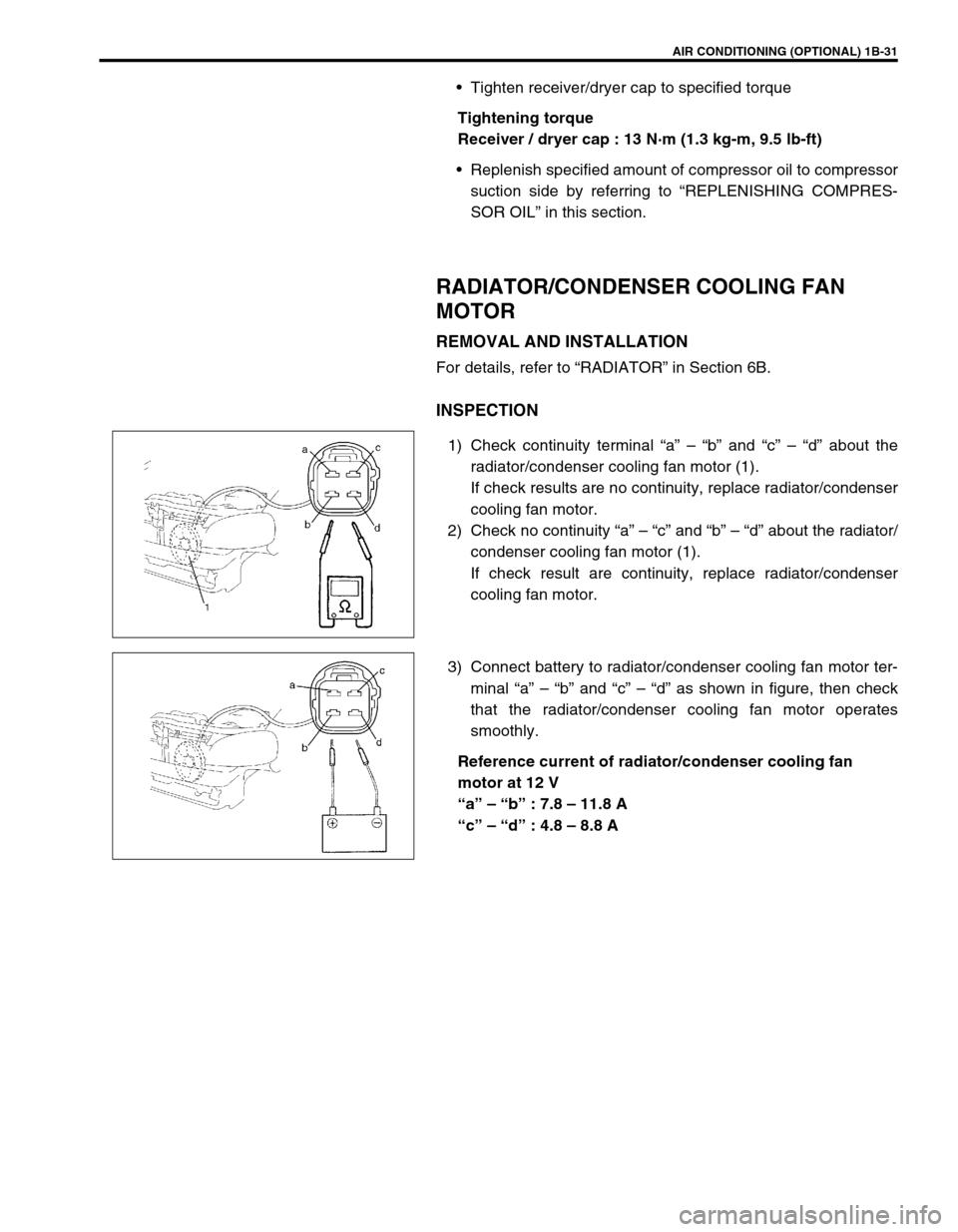
INSPECTION
1) Check continuity terminal “a” – “b” and “c” – “d” about the
radiator/condenser cooling fan motor (1).
If check results are no continuity, replace radiator/condenser
cooling fan motor.
2) Check no continuity “a” – “c” and “b” – “d” about the radiator/
condenser cooling fan motor (1).
If check result are continuity, replace radiator/condenser
cooling fan motor.
3) Connect battery to radiator/condenser cooling fan motor ter-
minal “a” – “b” and “c” – “d” as shown in figure, then check
that the radiator/condenser cooling fan motor operates
smoothly.
Reference current of radiator/condenser cooling fan
motor at 12 V
“a” – “b” : 7.8 – 11.8 A
“c” – “d” : 4.8 – 8.8 A
Page 101 of 698
1B-36 AIR CONDITIONING (OPTIONAL)
A/C SWITCH
REMOVAL AND INSTALLATION
Refer to “HEATER CONTROL ASSEMBLY” in Section 1A.
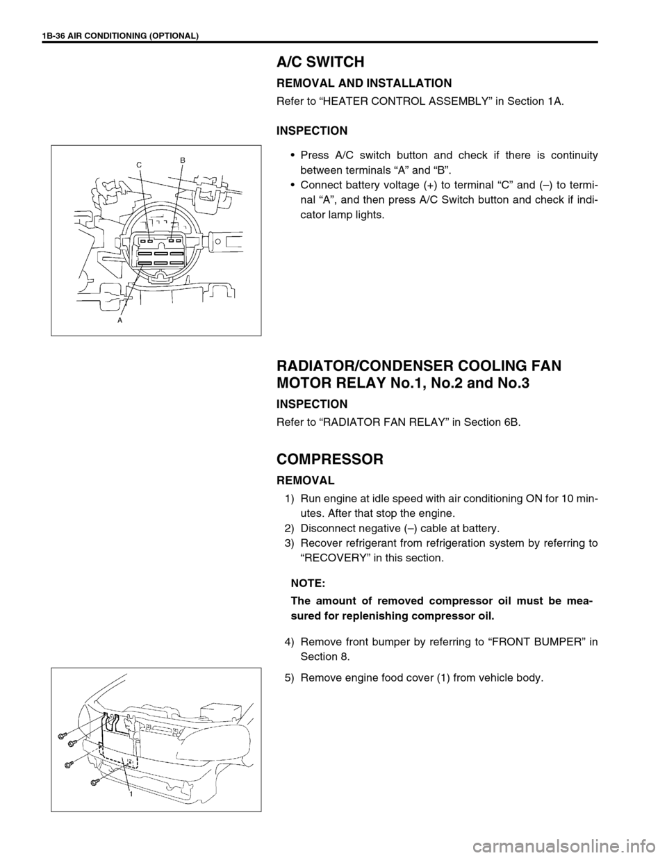
INSPECTION
Press A/C switch button and check if there is continuity
between terminals “A” and “B”.
Connect battery voltage (+) to terminal “C” and (–) to termi-
nal “A”, and then press A/C Switch button and check if indi-
cator lamp lights.
RADIATOR/CONDENSER COOLING FAN
MOTOR RELAY No.1, No.2 and No.3
INSPECTION
Refer to “RADIATOR FAN RELAY” in Section 6B.
COMPRESSOR
REMOVAL
1) Run engine at idle speed with air conditioning ON for 10 min-
utes. After that stop the engine.
2) Disconnect negative (–) cable at battery.
3) Recover refrigerant from refrigeration system by referring to
“RECOVERY” in this section.
4) Remove front bumper by referring to “FRONT BUMPER” in
Section 8.
5) Remove engine food cover (1) from vehicle body.
NOTE:
The amount of removed compressor oil must be mea-
sured for replenishing compressor oil.
Page 310 of 698
BRAKES 5-37
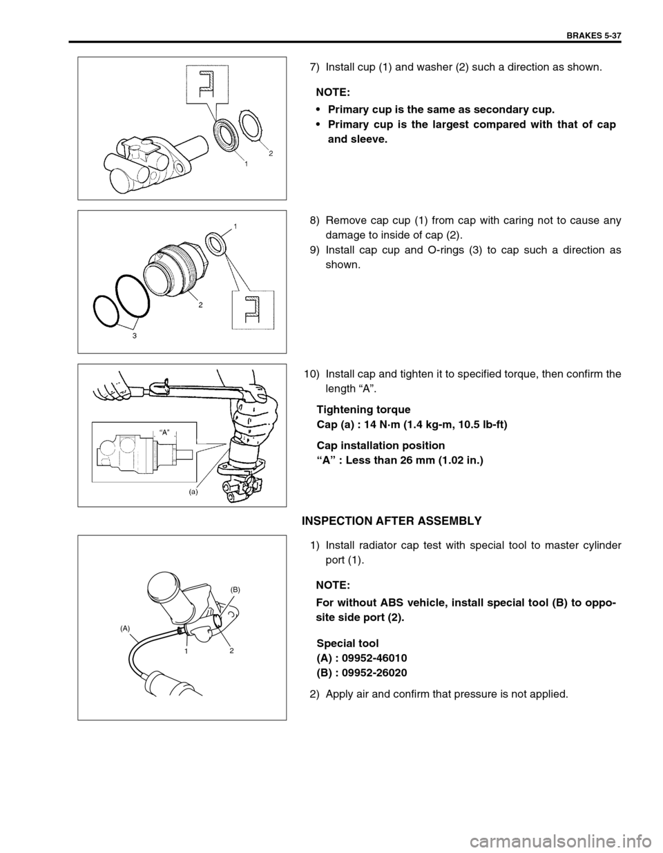
7) Install cup (1) and washer (2) such a direction as shown.
8) Remove cap cup (1) from cap with caring not to cause any
damage to inside of cap (2).
9) Install cap cup and O-rings (3) to cap such a direction as
shown.
10) Install cap and tighten it to specified torque, then confirm the
length “A”.
Tightening torque
Cap (a) : 14 N·m (1.4 kg-m, 10.5 lb-ft)
Cap installation position
“A” : Less than 26 mm (1.02 in.)
INSPECTION AFTER ASSEMBLY
1) Install radiator cap test with special tool to master cylinder
port (1).
Special tool
(A) : 09952-46010
(B) : 09952-26020
2) Apply air and confirm that pressure is not applied.NOTE:
Primary cup is the same as secondary cup.
Primary cup is the largest compared with that of cap
and sleeve.
NOTE:
For without ABS vehicle, install special tool (B) to oppo-
site side port (2).
1(B)
2 (A)
Page 311 of 698
5-38 BRAKES
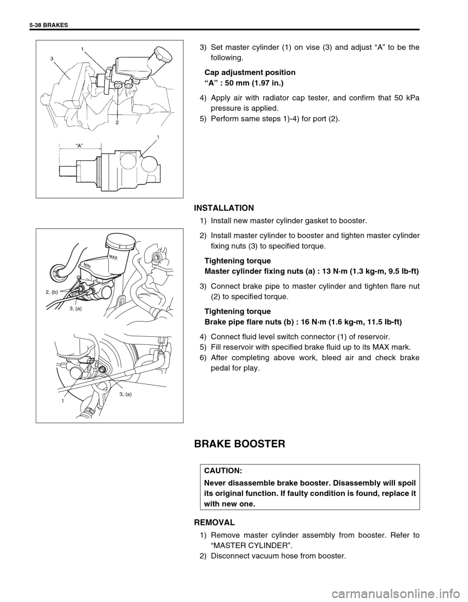
3) Set master cylinder (1) on vise (3) and adjust “A” to be the
following.
Cap adjustment position
“A” : 50 mm (1.97 in.)
4) Apply air with radiator cap tester, and confirm that 50 kPa
pressure is applied.
5) Perform same steps 1)-4) for port (2).
INSTALLATION
1) Install new master cylinder gasket to booster.
2) Install master cylinder to booster and tighten master cylinder
fixing nuts (3) to specified torque.
Tightening torque
Master cylinder fixing nuts (a) : 13 N·m (1.3 kg-m, 9.5 Ib-ft)
3) Connect brake pipe to master cylinder and tighten flare nut
(2) to specified torque.
Tightening torque
Brake pipe flare nuts (b) : 16 N·m (1.6 kg-m, 11.5 Ib-ft)
4) Connect fluid level switch connector (1) of reservoir.
5) Fill reservoir with specified brake fluid up to its MAX mark.
6) After completing above work, bleed air and check brake
pedal for play.
BRAKE BOOSTER
REMOVAL
1) Remove master cylinder assembly from booster. Refer to
“MASTER CYLINDER”.
2) Disconnect vacuum hose from booster.
3, (a)
1
3, (a) 2, (b)
CAUTION:
Never disassemble brake booster. Disassembly will spoil
its original function. If faulty condition is found, replace it
with new one.
Page 371 of 698
6-2 ENGINE GENERAL INFORMATION AND DIAGNOSIS
ENGINE DIAGNOSIS ......................................... 6-6
GENERAL DESCRIPTION ............................. 6-6
ON-BOARD DIAGNOSTIC SYSTEM
(VEHICLE WITH IMMOBILIZER INDICATOR
LAMP) ............................................................. 6-7
ON-BOARD DIAGNOSTIC SYSTEM
(VEHICLE WITHOUT IMMOBILIZER
INDICATOR LAMP) ...................................... 6-10
PRECAUTION IN DIAGNOSING
TROUBLE ..................................................... 6-11
ENGINE DIAGNOSTIC FLOW TABLE ......... 6-12
CUSTOMER PROBLEM INSPECTION
FORM (EXAMPLE) ................................... 6-14
MALFUNCTION INDICATOR LAMP (MIL)
CHECK...................................................... 6-15
DIAGNOSTIC TROUBLE CODE (DTC)
CHECK...................................................... 6-15
DIAGNOSTIC TROUBLE CODE (DTC)
CLEARANCE ............................................ 6-16
DIAGNOSTIC TROUBLE CODE (DTC)
TABLE ....................................................... 6-17
FAIL-SAFE TABLE.................................... 6-20
VISUAL INSPECTION .............................. 6-22
ENGINE BASIC INSPECTION.................. 6-23
ENGINE DIAGNOSIS TABLE ................... 6-26
SCAN TOOL DATA....................................... 6-31
INSPECTION OF ECM AND ITS
CIRCUITS ..................................................... 6-36
ECM VOLTAGE VALUES TABLE............. 6-37
TERMINAL RESISTANCE TABLE............ 6-43
COMPONENT LOCATION ........................... 6-45
TABLE A-1 MALFUNCTION INDICATOR
LAMP CIRCUIT CHECK - LAMP DOES NOT
COME “ON” AT IGNITION SWITCH ON
(BUT ENGINE AT STOP) ............................. 6-46
TABLE A-2 MALFUNCTION INDICATOR
LAMP CIRCUIT CHECK - LAMP REMAINS
“ON” AFTER ENGINE STARTS ................... 6-47
TABLE A-3 MIL CHECK - MIL FLASHES
AT IGNITION SWITCH ON (VEHICLE
WITHOUT IMMOBILIZER INDICATOR
LAMP) ........................................................... 6-48
TABLE A-4 MIL CHECK - MIL DOES NOT
FLASH OR JUST REMAINS ON EVEN
WITH GROUNDING DIAGNOSIS SWITCH
TERMINAL (VEHICLE WITHOUT
IMMOBILIZER INDICATOR LAMP) .............. 6-48
TABLE A-5 ECM POWER AND GROUND
CIRCUIT CHECK - MIL DOESN’T LIGHT
AT IGNITION SWITCH ON AND ENGINE
DOESN’T START THOUGH IT IS
CRANKED UP .............................................. 6-49
DTC P0105 (DTC NO.11) MANIFOLD
ABSOLUTE PRESSURE (MAP) CIRCUIT
MALFUNCTION ............................................ 6-52
DTC P0110 (DTC NO.18) INTAKE AIR
TEMP. (IAT) CIRCUIT MALFUNCTION ....... 6-55
DTC P0115 (DTC NO.19) ENGINE
COOLANT TEMPERATURE (ECT) CIRCUIT
MALFUNCTION ............................................ 6-57DTC P0120 (DTC NO.13) THROTTLE
POSITION CIRCUIT MALFUNCTION ........... 6-60
DTC P0121 THROTTLE POSITION CIRCUIT
RANGE/PERFORMANCE PROBLEM .......... 6-63
DTC P0130 (DTC NO.14) HEATED OXYGEN
SENSOR (HO2S) CIRCUIT MALFUNCTION
(SENSOR-1) .................................................. 6-66
DTC P0133 HEATED OXYGEN SENSOR
(HO2S) CIRCUIT SLOW RESPONSE
(SENSOR-1) .................................................. 6-68
DTC P0134 HEATED OXYGEN SENSOR
(HO2S) CIRCUIT NO ACTIVITY DETECTED
(SENSOR-1) .................................................. 6-69
DTC P0135 (DTC NO.14) HEATED OXYGEN
SENSOR (HO2S) HEATER CIRCUIT
MALFUNCTION (SENSOR-1) ....................... 6-70
DTC P0136 HEATED OXYGEN SENSOR
(HO2S) CIRCUIT MALFUNCTION
(SENSOR-2) .................................................. 6-72
DTC P0141 HEATED OXYGEN SENSOR
(HO2S) HEATER CIRCUIT MALFUNCTION
(SENSOR-2) .................................................. 6-74
DTC P0171 FUEL SYSTEM TOO LEAN ....... 6-76
DTC P0172 FUEL SYSTEM TOO RICH ....... 6-76
DTC P0300 RANDOM MISFIRE DETECTED
(MISFIRE DETECTED AT 2 OR MORE
CYLINDERS) ................................................. 6-81
DTC P0301 CYLINDER 1 MISFIRE
DETECTED ................................................... 6-81
DTC P0302 CYLINDER 2 MISFIRE
DETECTED ................................................... 6-81
DTC P0303 CYLINDER 3 MISFIRE
DETECTED ................................................... 6-81
DTC P0304 CYLINDER 4 MISFIRE
DETECTED ................................................... 6-81
DTC P0325 (DTC NO.17) KNOCK SENSOR
CIRCUIT MALFUNCTION ............................. 6-86
DTC P0335 (DTC NO.23) CRANKSHAFT
POSITION (CKP) SENSOR CIRCUIT
MALFUNCTION ............................................. 6-88
DTC P0340 (DTC NO.15) CAMSHAFT
POSITION (CMP) SENSOR CIRCUIT
MALFUNCTION ............................................. 6-91
DTC P0400 EXHAUST GAS
RECIRCULATION FLOW MALFUNCTION ... 6-94
DTC P0420 CATALYST SYSTEM
EFFICIENCY BELOW THRESHOLD ............ 6-97
DTC P0443 PURGE CONTROL VALVE
CIRCUIT MALFUNCTION ........................... 6-100
DTC P0480 RADIATOR COOLING FAN
CONTROL SYSTEM MALFUNCTION ........ 6-101
DTC P0500 (DTC NO.16) VEHICLE SPEED
SENSOR (VSS) MALFUNCTION ................ 6-103
DTC P0505 (DTC NO.26) IDLE CONTROL
SYSTEM MALFUNCTION ........................... 6-105
DTC P1450 BAROMETRIC PRESSURE
SENSOR LOW/HIGH INPUT....................... 6-108
DTC P1451 BAROMETRIC PRESSURE
SENSOR PERFORMANCE PROBLEM ...... 6-108
Page 372 of 698
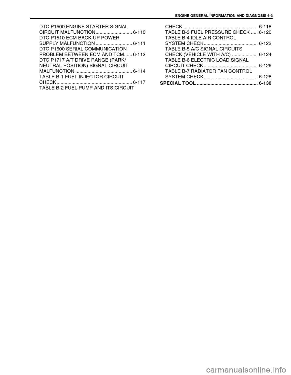
ENGINE GENERAL INFORMATION AND DIAGNOSIS 6-3
DTC P1500 ENGINE STARTER SIGNAL
CIRCUIT MALFUNCTION ........................... 6-110
DTC P1510 ECM BACK-UP POWER
SUPPLY MALFUNCTION ........................... 6-111
DTC P1600 SERIAL COMMUNICATION
PROBLEM BETWEEN ECM AND TCM...... 6-112
DTC P1717 A/T DRIVE RANGE (PARK/
NEUTRAL POSITION) SIGNAL CIRCUIT
MALFUNCTION .......................................... 6-114
TABLE B-1 FUEL INJECTOR CIRCUIT
CHECK ........................................................ 6-117
TABLE B-2 FUEL PUMP AND ITS CIRCUIT CHECK ....................................................... 6-118
TABLE B-3 FUEL PRESSURE CHECK ..... 6-120
TABLE B-4 IDLE AIR CONTROL
SYSTEM CHECK........................................ 6-122
TABLE B-5 A/C SIGNAL CIRCUITS
CHECK (VEHICLE WITH A/C) ................... 6-124
TABLE B-6 ELECTRIC LOAD SIGNAL
CIRCUIT CHECK ........................................ 6-126
TABLE B-7 RADIATOR FAN CONTROL
SYSTEM CHECK........................................ 6-128
SPECIAL TOOL ............................................. 6-130
Page 387 of 698
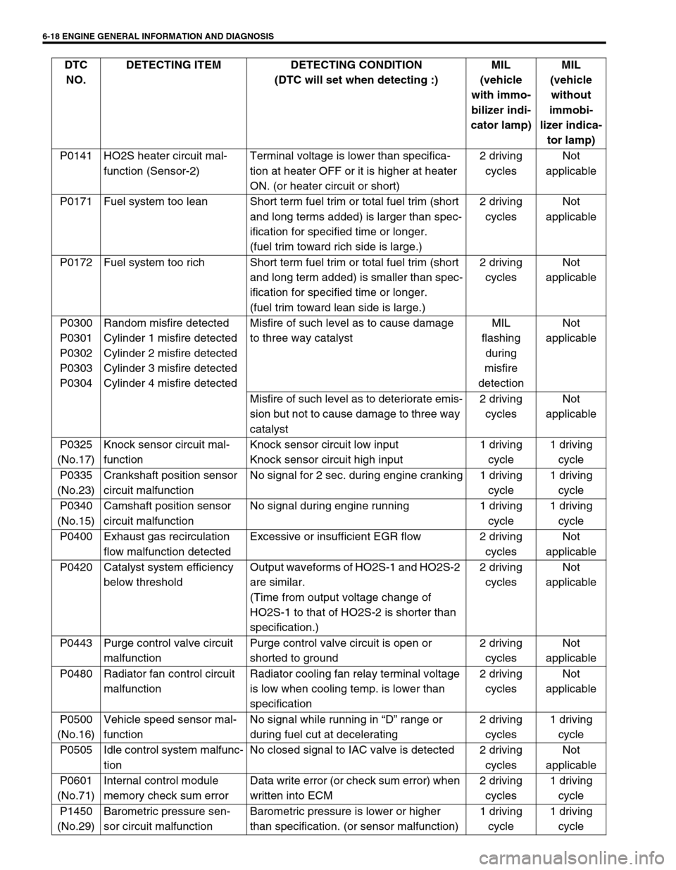
6-18 ENGINE GENERAL INFORMATION AND DIAGNOSIS
P0141 HO2S heater circuit mal-
function (Sensor-2)Terminal voltage is lower than specifica-
tion at heater OFF or it is higher at heater
ON. (or heater circuit or short)2 driving
cyclesNot
applicable
P0171 Fuel system too lean Short term fuel trim or total fuel trim (short
and long terms added) is larger than spec-
ification for specified time or longer.
(fuel trim toward rich side is large.)2 driving
cyclesNot
applicable
P0172 Fuel system too rich Short term fuel trim or total fuel trim (short
and long term added) is smaller than spec-
ification for specified time or longer.
(fuel trim toward lean side is large.)2 driving
cyclesNot
applicable
P0300
P0301
P0302
P0303
P0304Random misfire detected
Cylinder 1 misfire detected
Cylinder 2 misfire detected
Cylinder 3 misfire detected
Cylinder 4 misfire detectedMisfire of such level as to cause damage
to three way catalystMIL
flashing
during
misfire
detectionNot
applicable
Misfire of such level as to deteriorate emis-
sion but not to cause damage to three way
catalyst2 driving
cyclesNot
applicable
P0325
(No.17)Knock sensor circuit mal-
functionKnock sensor circuit low input
Knock sensor circuit high input1 driving
cycle1 driving
cycle
P0335
(No.23)Crankshaft position sensor
circuit malfunctionNo signal for 2 sec. during engine cranking 1 driving
cycle1 driving
cycle
P0340
(No.15)Camshaft position sensor
circuit malfunctionNo signal during engine running 1 driving
cycle1 driving
cycle
P0400 Exhaust gas recirculation
flow malfunction detectedExcessive or insufficient EGR flow 2 driving
cyclesNot
applicable
P0420 Catalyst system efficiency
below thresholdOutput waveforms of HO2S-1 and HO2S-2
are similar.
(Time from output voltage change of
HO2S-1 to that of HO2S-2 is shorter than
specification.)2 driving
cyclesNot
applicable
P0443 Purge control valve circuit
malfunctionPurge control valve circuit is open or
shorted to ground2 driving
cyclesNot
applicable
P0480 Radiator fan control circuit
malfunctionRadiator cooling fan relay terminal voltage
is low when cooling temp. is lower than
specification2 driving
cyclesNot
applicable
P0500
(No.16)Vehicle speed sensor mal-
functionNo signal while running in “D” range or
during fuel cut at decelerating2 driving
cycles1 driving
cycle
P0505 Idle control system malfunc-
tionNo closed signal to IAC valve is detected 2 driving
cyclesNot
applicable
P0601
(No.71)Internal control module
memory check sum errorData write error (or check sum error) when
written into ECM2 driving
cycles1 driving
cycle
P1450
(No.29)Barometric pressure sen-
sor circuit malfunctionBarometric pressure is lower or higher
than specification. (or sensor malfunction)1 driving
cycle1 driving
cycle DTC
NO.DETECTING ITEM DETECTING CONDITION
(DTC will set when detecting :)MIL
(vehicle
with immo-
bilizer indi-
cator lamp)MIL
(vehicle
without
immobi-
lizer indica-
tor lamp)