Brake SUZUKI SWIFT 2000 1.G RG413 Service Owner's Manual
[x] Cancel search | Manufacturer: SUZUKI, Model Year: 2000, Model line: SWIFT, Model: SUZUKI SWIFT 2000 1.GPages: 698, PDF Size: 16.01 MB
Page 155 of 698

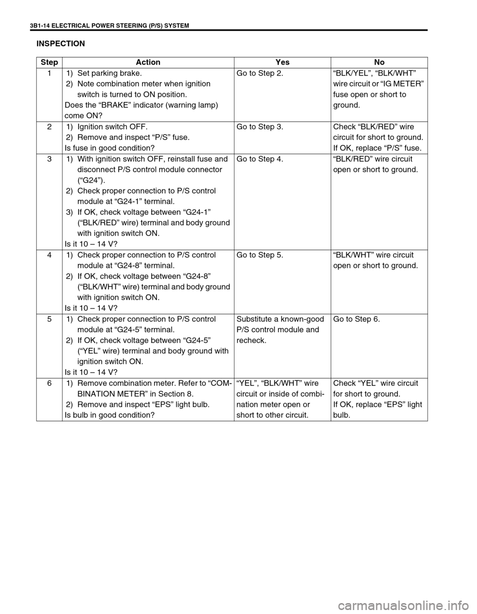
3B1-14 ELECTRICAL POWER STEERING (P/S) SYSTEM
INSPECTION
Step Action Yes No
1 1) Set parking brake.
2) Note combination meter when ignition
switch is turned to ON position.
Does the “BRAKE” indicator (warning lamp)
come ON?Go to Step 2.“BLK/YEL”, “BLK/WHT”
wire circuit or “IG METER”
fuse open or short to
ground.
2 1) Ignition switch OFF.
2) Remove and inspect “P/S” fuse.
Is fuse in good condition?Go to Step 3. Check “BLK/RED” wire
circuit for short to ground.
If OK, replace “P/S” fuse.
3 1) With ignition switch OFF, reinstall fuse and
disconnect P/S control module connector
(“G24”).
2) Check proper connection to P/S control
module at “G24-1” terminal.
3) If OK, check voltage between “G24-1”
(“BLK/RED” wire) terminal and body ground
with ignition switch ON.
Is it 10 – 14 V?Go to Step 4.“BLK/RED” wire circuit
open or short to ground.
4 1) Check proper connection to P/S control
module at “G24-8” terminal.
2) If OK, check voltage between “G24-8”
(“BLK/WHT” wire) terminal and body ground
with ignition switch ON.
Is it 10 – 14 V?Go to Step 5.“BLK/WHT” wire circuit
open or short to ground.
5 1) Check proper connection to P/S control
module at “G24-5” terminal.
2) If OK, check voltage between “G24-5”
(“YEL” wire) terminal and body ground with
ignition switch ON.
Is it 10 – 14 V?Substitute a known-good
P/S control module and
recheck.Go to Step 6.
6 1) Remove combination meter. Refer to “COM-
BINATION METER” in Section 8.
2) Remove and inspect “EPS” light bulb.
Is bulb in good condition?“YEL”, “BLK/WHT” wire
circuit or inside of combi-
nation meter open or
short to other circuit.Check “YEL” wire circuit
for short to ground.
If OK, replace “EPS” light
bulb.
Page 195 of 698
![SUZUKI SWIFT 2000 1.G RG413 Service Owners Manual 3D-2 FRONT SUSPENSION
1. Strut assembly 4. Wheel 7. Drive shaft [A] : FORWARD
2. Stabilizer bar 5. Suspension control arm 8. Tie rod Tightening torque
3. Steering knuckle 6. Vehicle body 9. Brake disc SUZUKI SWIFT 2000 1.G RG413 Service Owners Manual 3D-2 FRONT SUSPENSION
1. Strut assembly 4. Wheel 7. Drive shaft [A] : FORWARD
2. Stabilizer bar 5. Suspension control arm 8. Tie rod Tightening torque
3. Steering knuckle 6. Vehicle body 9. Brake disc](/img/20/7606/w960_7606-194.png)
3D-2 FRONT SUSPENSION
1. Strut assembly 4. Wheel 7. Drive shaft [A] : FORWARD
2. Stabilizer bar 5. Suspension control arm 8. Tie rod Tightening torque
3. Steering knuckle 6. Vehicle body 9. Brake disc Do not reuse.
[A]
4
92
35
8
660 N·m(6.0 kg-m) 175 N·m(17.5 kg-m)
60 N·m(6.0 kg-m)
85 N·m(8.5 kg-m)
85 N·m(8.5 kg-m)
43 N·m(4.3 kg-m)
65 N·m(6.5 kg-m)
65 N·m(6.5 kg-m)
23 N·m(2.3 kg-m)
50 N·m(5.0 kg-m)
175 N·m(17.5 kg-m)
105 N·m(10.5 kg-m)
1
8
45 N·m (4.5kg-m) 7
5
4
9
Page 199 of 698

3D-6 FRONT SUSPENSION
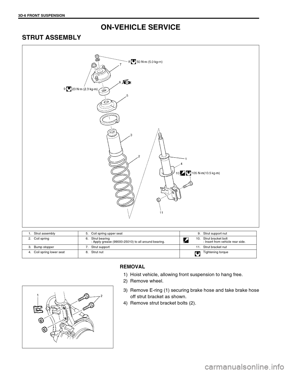
ON-VEHICLE SERVICE
STRUT ASSEMBLY
REMOVAL
1) Hoist vehicle, allowing front suspension to hang free.
2) Remove wheel.
3) Remove E-ring (1) securing brake hose and take brake hose
off strut bracket as shown.
4) Remove strut bracket bolts (2).
1. Strut assembly 5. Coil spring upper seat 9. Strut support nut
2. Coil spring 6. Strut bearing
: Apply grease (99000-25010) to all around bearing.10. Strut bracket bolt
: Insert from vehicle rear side.
3. Bump stopper 7. Strut support 11. Strut bracket nut
4. Coil spring lower seat 8. Strut nut Tightening torque
Page 201 of 698

3D-8 FRONT SUSPENSION
Tighten strut nut to specified torque by using special tools.
Tightening torque
Strut nut (a) : 50 N·m (5.0 kg-m, 36.5 lb-ft)
Special tool
(A) : 09900-00411
(B) : 09900-00414
(C) : 09945-26010
INSTALLATION
Install strut assembly by reversing removal procedure, noting the
following instructions.
Insert bolts in such direction as shown in figure.
Tighten all fasteners to specified torque.
Tightening torque
Strut bracket nut (a) : 105 N·m (10.5 kg-m, 76.0 lb-ft)
Strut support nut (b) : 23 N·m (2.3 kg-m, 17.0 lb-ft)
Tighten wheel nut to specified torque.
Tightening torque
Wheel nut : 85 N·m (8.5 kg-m, 61.5 lb-ft)
After installation, confirm front end (wheel) alignment refer-
ring to Section 3A.
NOTE:
Don’t twist brake hose when installing it.
Install E-ring (1) as far as it fits to bracket (2) as shown
in figure.
Page 204 of 698

FRONT SUSPENSION 3D-11
WHEEL HUB AND STEERING KNUCKLE
REMOVAL
1) Hoist vehicle and remove wheel.
2) Uncaulk drive shaft nut (1).
3) Depress foot brake pedal and hold it there. Remove drive
shaft nut (1).
4) Remove caliper carrier bolts.
5) Remove caliper (1) with carrier.
6) Pull brake disc (2) off by using two 8 mm bolts.
1. Front wheel hub 4. Steering knuckle Tightening torque
2. Circlip 5. Drive shaft nut
: Calk, after tightening.Do not reuse.
3. Wheel bearing
: Face grooved rubber seal side to wheel hub.6. Hub bolt
NOTE:
Hang removed caliper with a wire hook or the like (3) so
as to prevent brake hose (4) from bending and twisting
excessively or being pulled.
Don’t operate brake pedal with pads removed.
Page 209 of 698

3D-16 FRONT SUSPENSION
Connect tie rod end (1) to steering knuckle (2) and tighten tie
rod end castle nut (3) to specified torque.
Tightening torque
The rod end castle nut (a) : 43 N·m (4.3 kg-m, 31.5 lb-ft)
Install new split pin (4).
Install brake disc (2) and brake caliper (3).
Tighten brake caliper bolt to specified torque.
Tightening torque
Brake caliper bolt : 85 N·m (8.5 kg-m, 61.5 lb-ft)
Depress foot brake pedal and hold it there.
Tighten new drive shaft nut (1) to specified torque.
Tightening torque
Drive shaft nut (a) : 175 N·m (17.5 kg-m, 127.0 lb-ft)
Caulk drive shaft nut (1) as shown.
Caulking specification
“a” : 0.5 mm (0.02 in.) or more
Tightening wheel nut to specified torque.
Tightening torque
Wheel nut : 85 N·m (8.5 kg-m, 61.5 lb-ft)
SUSPENSION CONTROL ARM / BUSHING
REMOVAL
1) Remove stabilizer bar. Refer to “STABILIZER BAR AND/OR
BUSHINGS” in this section.
2) Remove suspension control arm ball joint bolt (1).
CAUTION:
Never reuse drive shaft nut (1).
CAUTION:
Be careful while caulking nut so that no crack will occur
in caulked part of nut. Cracked nut must be replaced with
new one.
F: Forward
Page 215 of 698

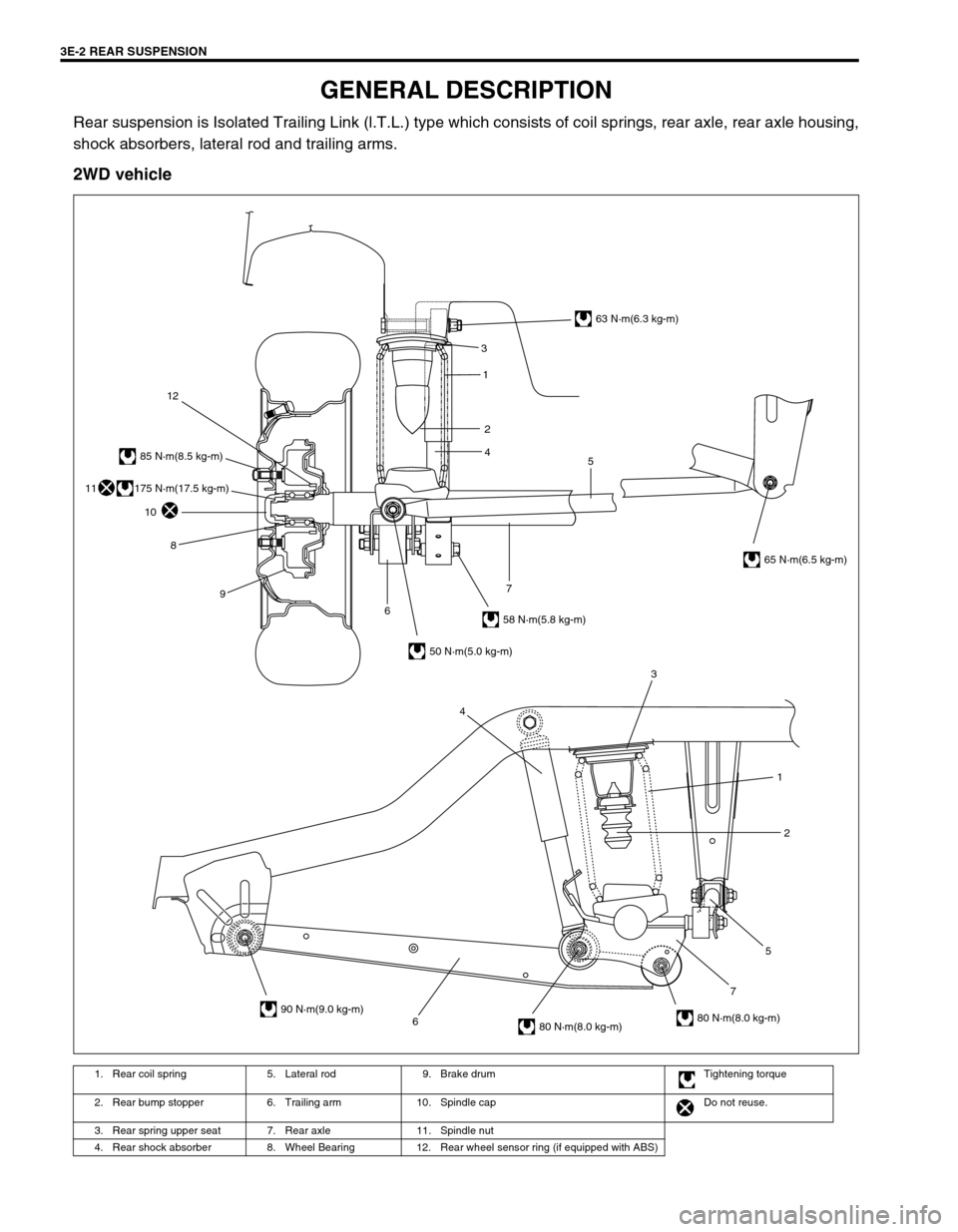
3E-2 REAR SUSPENSION
GENERAL DESCRIPTION
Rear suspension is Isolated Trailing Link (l.T.L.) type which consists of coil springs, rear axle, rear axle housing,
shock absorbers, lateral rod and trailing arms.
2WD vehicle
1. Rear coil spring 5. Lateral rod 9. Brake drum Tightening torque
2. Rear bump stopper 6. Trailing arm 10. Spindle cap Do not reuse.
3. Rear spring upper seat 7. Rear axle 11. Spindle nut
4. Rear shock absorber 8. Wheel Bearing 12. Rear wheel sensor ring (if equipped with ABS)
6752 1 3
4
3
5 1
2
4
63 N·m(6.3 kg-m)
65 N·m(6.5 kg-m)
58 N·m(5.8 kg-m)
50 N·m(5.0 kg-m)
90 N·m(9.0 kg-m)
80 N·m(8.0 kg-m)80 N·m(8.0 kg-m)
85 N·m(8.5 kg-m)
12
10
8
9
67
175 N·m(17.5 kg-m)11
Page 216 of 698

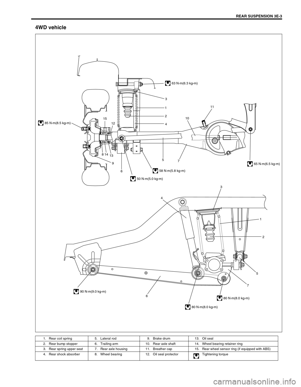
REAR SUSPENSION 3E-3
4WD vehicle
1. Rear coil spring 5. Lateral rod 9. Brake drum 13. Oil seal
2. Rear bump stopper 6. Trailing arm 10. Rear axle shaft 14. Wheel bearing retainer ring
3. Rear spring upper seat 7. Rear axle housing 11. Breather cap 15. Rear wheel sensor ring (if equipped with ABS)
4. Rear shock absorber 8. Wheel bearing 12. Oil seal protector Tightening torque
6752 1 3
4
63 N·m(6.3 kg-m)
58 N·m(5.8 kg-m)
50 N·m(5.0 kg-m)
85 N·m(8.5 kg-m)
90 N·m(9.0 kg-m)
80 N·m(8.0 kg-m)
80 N·m(8.0 kg-m)
65 N·m(6.5 kg-m) 3
1
2
4
7 5
6 9 814
1312 151011
Page 221 of 698

3E-8 REAR SUSPENSION
3) Remove lateral rod right side bolt (1) and nut (2).
4) Detach lateral rod right side from vehicle body.
5) Remove brake flexible hose E-ring (1).
6) Remove LSPV adjust nut and detach spring end from rear
axle (2WD vehicle) or axle housing (4WD vehicle) (if
equipped with LSPV).
7) Remove shock absorber lower bolt (1).
8) Detach shock absorber lower side from rear axle (2WD vehi-
cle) or rear axle housing (4WD vehicle).
9) Lower rear axle (1) (2WD vehicle) or rear axle housing (4WD
vehicle) gradually as far down as where coil springs (2) can
be removed.
10) Remove coil spring.
CAUTION:
Be careful not to let rear axle (2WD vehicle) or rear axle
housing (4WD vehicle) down too much.
It may cause damage to brake flexible hose.
Page 222 of 698

REAR SUSPENSION 3E-9
INSTALLATION
1) Install coil springs (1) (right & left) on spring seat (2) of rear
axle (2WD vehicle) or rear axle housing (4WD vehicle) and
raise rear axle (2WD vehicle) or rear axle housing (4WD
vehicle).
2) Install shock absorber (1) lower side to rear axle (2WD vehi-
cle) or rear axle housing (4WD vehicle).
Tighten shock absorber lower bolt (2) temporarily at this
step.
3) Remove floor jack from rear axle (2WD vehicle) or axle
housing (4WD vehicle).
4) Install brake flexible hose E-ring.
5) Install LSPV spring to rear axle (2WD vehicle) or axle hous-
ing (4WD vehicle). Tighten LSPV adjust nut temporarily at
this step (if equipped with LSPV).
6) Install lateral rod (1) right side to vehicle body, refer to the
figure for proper installing direction of bolt (2).
Tighten nut (3) temporarily at this step.
7) Remove floor jack from rear axle (2WD vehicle) or rear axle
housing (4WD vehicle).
8) Install wheel (1) and tighten wheel nuts (2) to specified
torque.
Tightening torque
Wheel nuts (a) : 85 N·m (8.5 kg-m, 61.5 lb-ft) NOTE:
Upper and lower diameters of coil spring are different.
Bring larger diameter end at bottom and set its open end
in place on spring seat.
A : Upper side
A : Forward