brake sensor SUZUKI SWIFT 2000 1.G RG413 Service Workshop Manual
[x] Cancel search | Manufacturer: SUZUKI, Model Year: 2000, Model line: SWIFT, Model: SUZUKI SWIFT 2000 1.GPages: 698, PDF Size: 16.01 MB
Page 25 of 698
0A-22 GENERAL INFORMATION
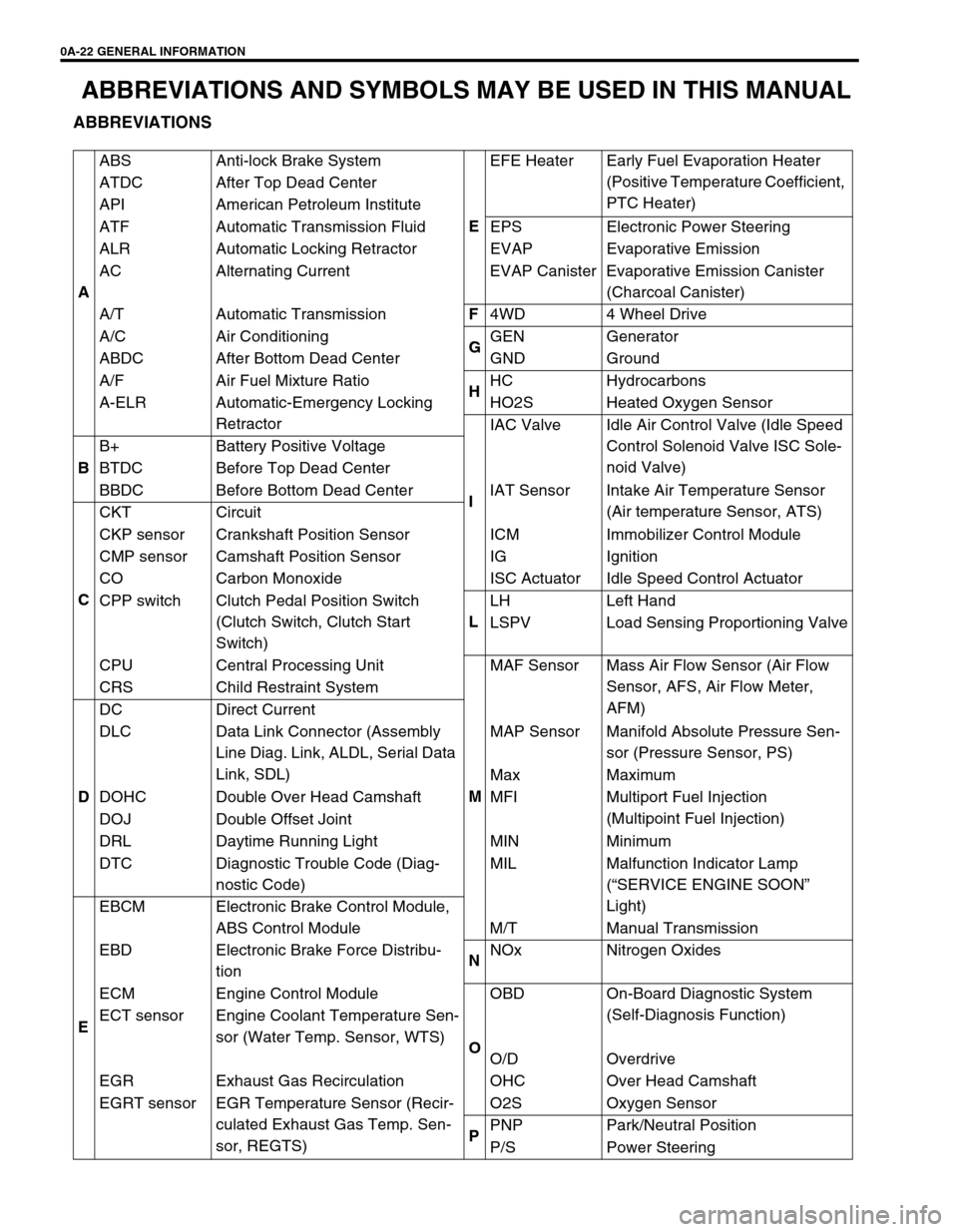
ABBREVIATIONS AND SYMBOLS MAY BE USED IN THIS MANUAL
ABBREVIATIONS
AABS Anti-lock Brake System
EEFE Heater Early Fuel Evaporation Heater
(Positive Temperature Coefficient,
PTC Heater) ATDC After Top Dead Center
API American Petroleum Institute
ATF Automatic Transmission Fluid EPS Electronic Power Steering
ALR Automatic Locking Retractor EVAP Evaporative Emission
AC Alternating Current EVAP Canister Evaporative Emission Canister
(Charcoal Canister)
A/T Automatic TransmissionF
4WD 4 Wheel Drive
A/C Air Conditioning
GGEN Generator
ABDC After Bottom Dead Center GND Ground
A/F Air Fuel Mixture Ratio
HHC Hydrocarbons
A-ELR Automatic-Emergency Locking
RetractorHO2S Heated Oxygen Sensor
IIAC Valve Idle Air Control Valve (Idle Speed
Control Solenoid Valve ISC Sole-
noid Valve)
BB+ Battery Positive Voltage
BTDC Before Top Dead Center
BBDC Before Bottom Dead Center IAT Sensor Intake Air Temperature Sensor
(Air temperature Sensor, ATS)
CCKT Circuit
CKP sensor Crankshaft Position Sensor ICM Immobilizer Control Module
CMP sensor Camshaft Position Sensor IG Ignition
CO Carbon Monoxide ISC Actuator Idle Speed Control Actuator
CPP switch Clutch Pedal Position Switch
(Clutch Switch, Clutch Start
Switch)LLH Left Hand
LSPV Load Sensing Proportioning Valve
CPU Central Processing Unit
MMAF Sensor Mass Air Flow Sensor (Air Flow
Sensor, AFS, Air Flow Meter,
AFM) CRS Child Restraint System
DDC Direct Current
DLC Data Link Connector (Assembly
Line Diag. Link, ALDL, Serial Data
Link, SDL)MAP Sensor Manifold Absolute Pressure Sen-
sor (Pressure Sensor, PS)
Max Maximum
DOHC Double Over Head Camshaft MFI Multiport Fuel Injection
(Multipoint Fuel Injection)
DOJ Double Offset Joint
DRL Daytime Running Light MIN Minimum
DTC Diagnostic Trouble Code (Diag-
nostic Code)MIL Malfunction Indicator Lamp
(“SERVICE ENGINE SOON”
Light)
EEBCM Electronic Brake Control Module,
ABS Control Module M/T Manual Transmission
EBD Electronic Brake Force Distribu-
tionNNOx Nitrogen Oxides
ECM Engine Control Module
OOBD On-Board Diagnostic System
(Self-Diagnosis Function)
ECT sensor Engine Coolant Temperature Sen-
sor (Water Temp. Sensor, WTS)
O/D Overdrive
EGR Exhaust Gas Recirculation OHC Over Head Camshaft
EGRT sensor EGR Temperature Sensor (Recir-
culated Exhaust Gas Temp. Sen-
sor, REGTS)O2S Oxygen Sensor
PPNP Park/Neutral Position
P/S Power Steering
Page 215 of 698
3E-2 REAR SUSPENSION
GENERAL DESCRIPTION
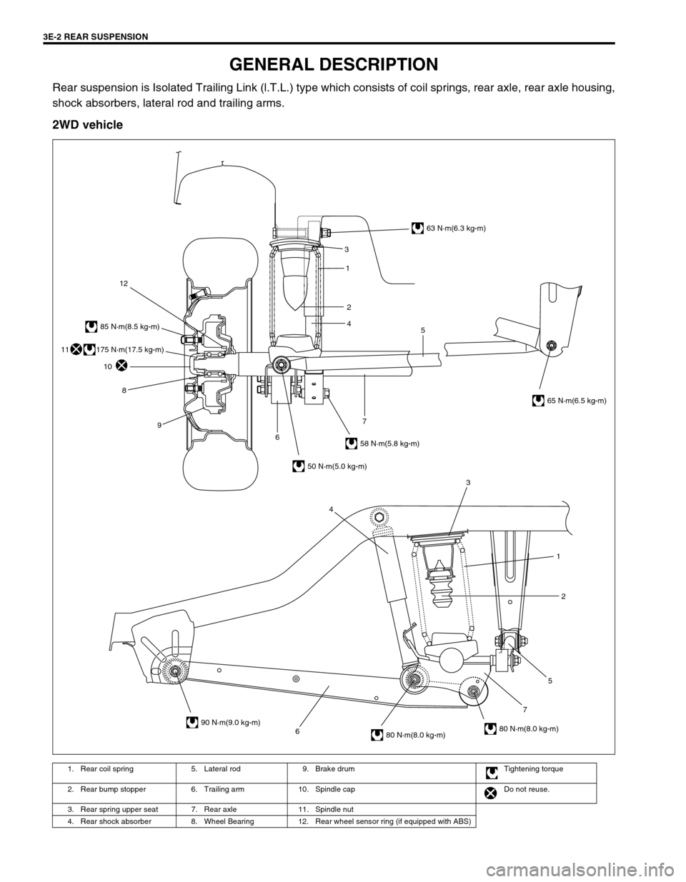
Rear suspension is Isolated Trailing Link (l.T.L.) type which consists of coil springs, rear axle, rear axle housing,
shock absorbers, lateral rod and trailing arms.
2WD vehicle
1. Rear coil spring 5. Lateral rod 9. Brake drum Tightening torque
2. Rear bump stopper 6. Trailing arm 10. Spindle cap Do not reuse.
3. Rear spring upper seat 7. Rear axle 11. Spindle nut
4. Rear shock absorber 8. Wheel Bearing 12. Rear wheel sensor ring (if equipped with ABS)
6752 1 3
4
3
5 1
2
4
63 N·m(6.3 kg-m)
65 N·m(6.5 kg-m)
58 N·m(5.8 kg-m)
50 N·m(5.0 kg-m)
90 N·m(9.0 kg-m)
80 N·m(8.0 kg-m)80 N·m(8.0 kg-m)
85 N·m(8.5 kg-m)
12
10
8
9
67
175 N·m(17.5 kg-m)11
Page 216 of 698
REAR SUSPENSION 3E-3
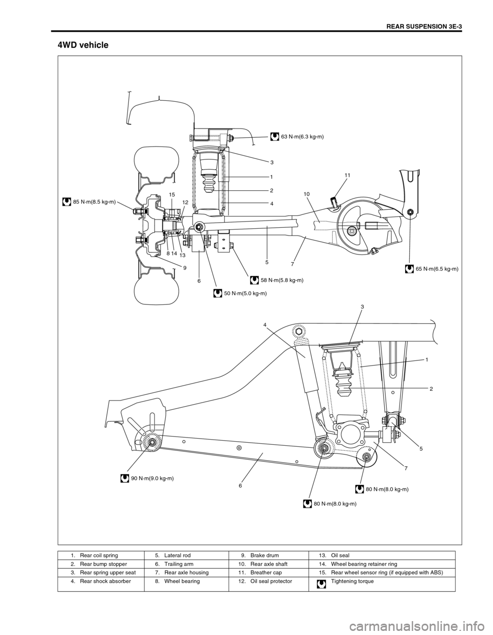
4WD vehicle
1. Rear coil spring 5. Lateral rod 9. Brake drum 13. Oil seal
2. Rear bump stopper 6. Trailing arm 10. Rear axle shaft 14. Wheel bearing retainer ring
3. Rear spring upper seat 7. Rear axle housing 11. Breather cap 15. Rear wheel sensor ring (if equipped with ABS)
4. Rear shock absorber 8. Wheel bearing 12. Oil seal protector Tightening torque
6752 1 3
4
63 N·m(6.3 kg-m)
58 N·m(5.8 kg-m)
50 N·m(5.0 kg-m)
85 N·m(8.5 kg-m)
90 N·m(9.0 kg-m)
80 N·m(8.0 kg-m)
80 N·m(8.0 kg-m)
65 N·m(6.5 kg-m) 3
1
2
4
7 5
6 9 814
1312 151011
Page 225 of 698
3E-12 REAR SUSPENSION
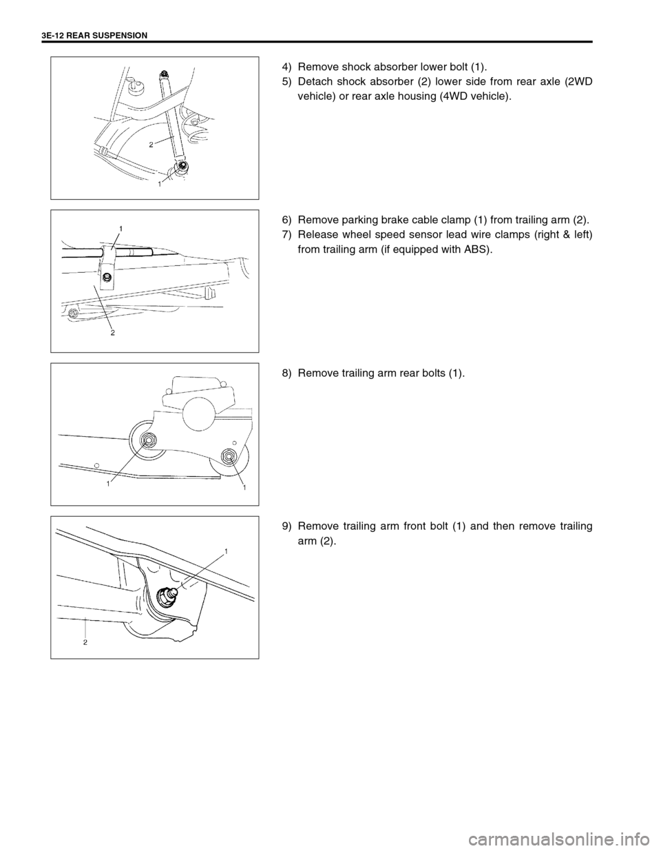
4) Remove shock absorber lower bolt (1).
5) Detach shock absorber (2) lower side from rear axle (2WD
vehicle) or rear axle housing (4WD vehicle).
6) Remove parking brake cable clamp (1) from trailing arm (2).
7) Release wheel speed sensor lead wire clamps (right & left)
from trailing arm (if equipped with ABS).
8) Remove trailing arm rear bolts (1).
9) Remove trailing arm front bolt (1) and then remove trailing
arm (2).
Page 226 of 698
REAR SUSPENSION 3E-13
INSTALLATION
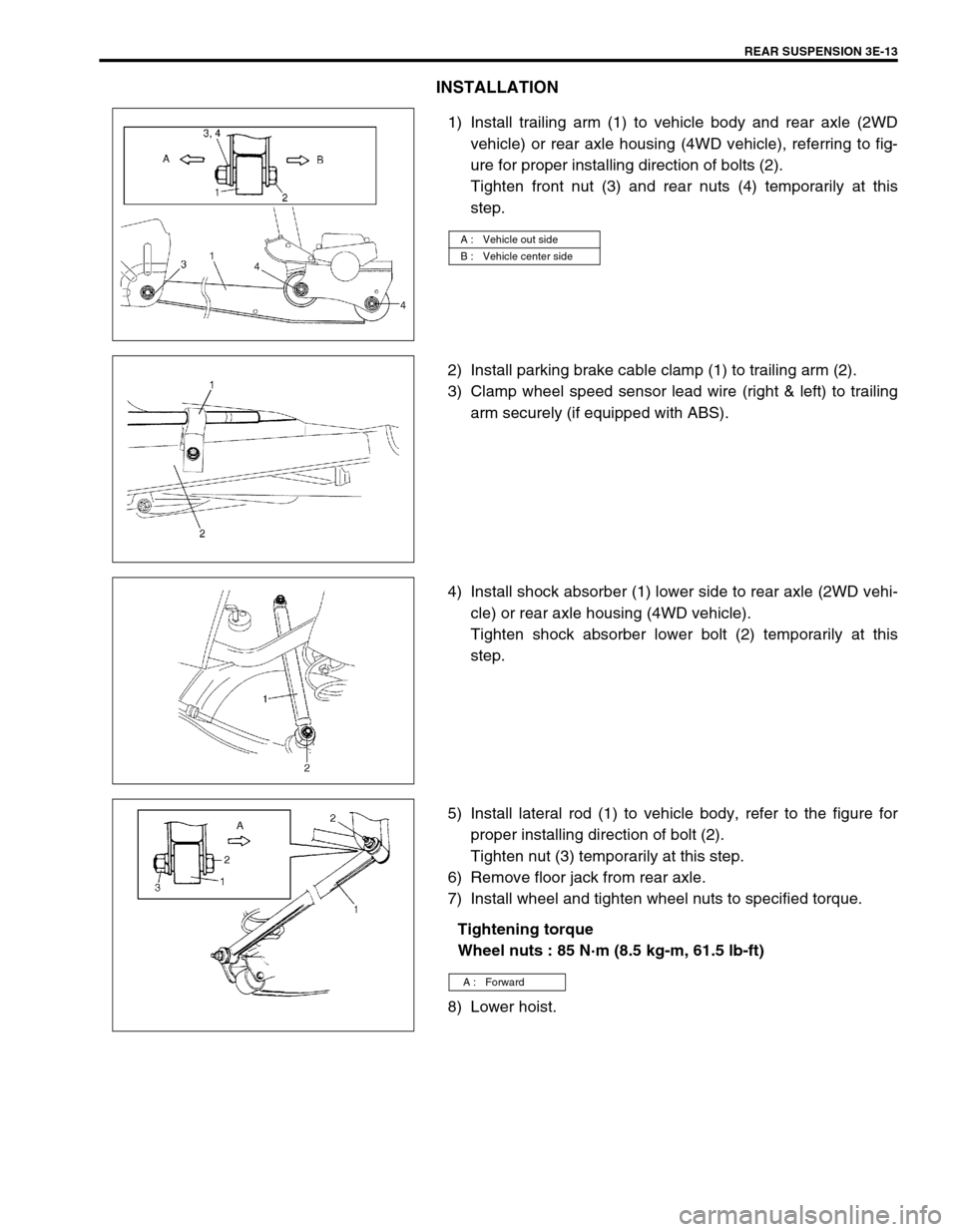
1) Install trailing arm (1) to vehicle body and rear axle (2WD
vehicle) or rear axle housing (4WD vehicle), referring to fig-
ure for proper installing direction of bolts (2).
Tighten front nut (3) and rear nuts (4) temporarily at this
step.
2) Install parking brake cable clamp (1) to trailing arm (2).
3) Clamp wheel speed sensor lead wire (right & left) to trailing
arm securely (if equipped with ABS).
4) Install shock absorber (1) lower side to rear axle (2WD vehi-
cle) or rear axle housing (4WD vehicle).
Tighten shock absorber lower bolt (2) temporarily at this
step.
5) Install lateral rod (1) to vehicle body, refer to the figure for
proper installing direction of bolt (2).
Tighten nut (3) temporarily at this step.
6) Remove floor jack from rear axle.
7) Install wheel and tighten wheel nuts to specified torque.
Tightening torque
Wheel nuts : 85 N·m (8.5 kg-m, 61.5 lb-ft)
8) Lower hoist.
A : Vehicle out side
B : Vehicle center side
A : Forward
Page 228 of 698
REAR SUSPENSION 3E-15
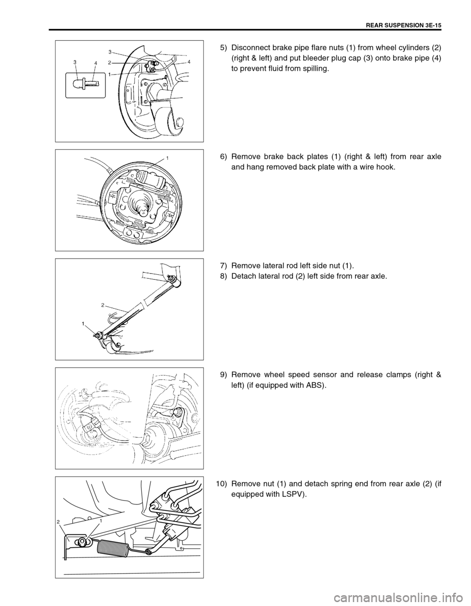
5) Disconnect brake pipe flare nuts (1) from wheel cylinders (2)
(right & left) and put bleeder plug cap (3) onto brake pipe (4)
to prevent fluid from spilling.
6) Remove brake back plates (1) (right & left) from rear axle
and hang removed back plate with a wire hook.
7) Remove lateral rod left side nut (1).
8) Detach lateral rod (2) left side from rear axle.
9) Remove wheel speed sensor and release clamps (right &
left) (if equipped with ABS).
10) Remove nut (1) and detach spring end from rear axle (2) (if
equipped with LSPV).
21
Page 231 of 698
3E-18 REAR SUSPENSION
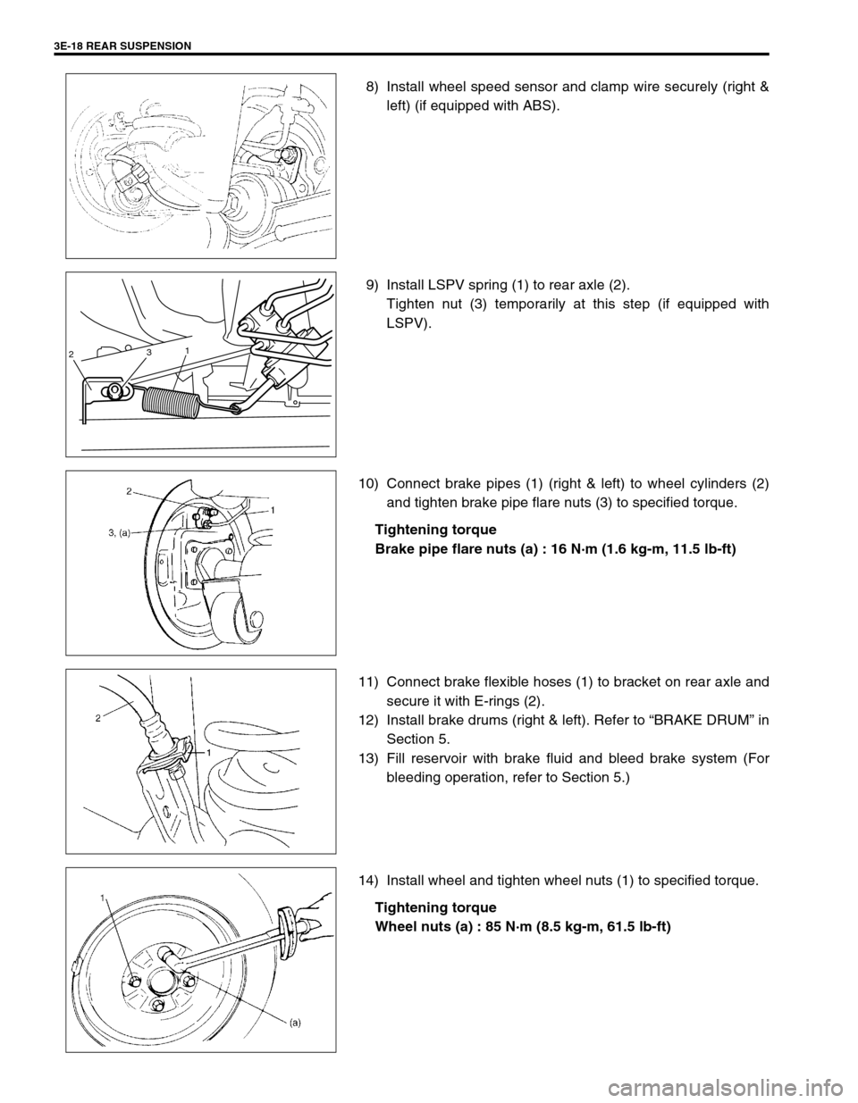
8) Install wheel speed sensor and clamp wire securely (right &
left) (if equipped with ABS).
9) Install LSPV spring (1) to rear axle (2).
Tighten nut (3) temporarily at this step (if equipped with
LSPV).
10) Connect brake pipes (1) (right & left) to wheel cylinders (2)
and tighten brake pipe flare nuts (3) to specified torque.
Tightening torque
Brake pipe flare nuts (a) : 16 N·m (1.6 kg-m, 11.5 lb-ft)
11) Connect brake flexible hoses (1) to bracket on rear axle and
secure it with E-rings (2).
12) Install brake drums (right & left). Refer to “BRAKE DRUM” in
Section 5.
13) Fill reservoir with brake fluid and bleed brake system (For
bleeding operation, refer to Section 5.)
14) Install wheel and tighten wheel nuts (1) to specified torque.
Tightening torque
Wheel nuts (a) : 85 N·m (8.5 kg-m, 61.5 lb-ft)
231
Page 232 of 698
REAR SUSPENSION 3E-19
15) Upon completion of all jobs, depress brake pedal with about
30 kg (66 Ibs) load three to five times so as to obtain proper
drum-to-shoe clearance.
Adjust parking brake cable. Refer to Section 5.
16) Install console box.
17) Lower hoist and bounce vehicle up and down several times
to stabilize suspension.
Be sure that vehicle is off hoist and in non loaded condition.
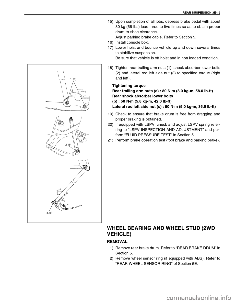
18) Tighten rear trailing arm nuts (1), shock absorber lower bolts
(2) and lateral rod left side nut (3) to specified torque (right
and left).
Tightening torque
Rear trailing arm nuts (a) : 80 N·m (8.0 kg-m, 58.0 lb-ft)
Rear shock absorber lower bolts
(b) : 58 N·m (5.8 kg-m, 42.0 lb-ft)
Lateral rod left side nut (c) : 50 N·m (5.0 kg-m, 36.5 lb-ft)
19) Check to ensure that brake drum is free from dragging and
proper braking is obtained.
20) If equipped with LSPV, check and adjust LSPV spring refer-
ring to “LSPV INSPECTION AND ADJUSTMENT” and per-
form “FLUID PRESSURE TEST” in Section 5.
21) Perform brake operation test (foot brake and parking brake).
WHEEL BEARING AND WHEEL STUD (2WD
VEHICLE)
REMOVAL
1) Remove rear brake drum. Refer to “REAR BRAKE DRUM” in
Section 5.
2) Remove wheel sensor ring (if equipped with ABS). Refer to
“REAR WHEEL SENSOR RING” of Section 5E.
Page 234 of 698
REAR SUSPENSION 3E-21
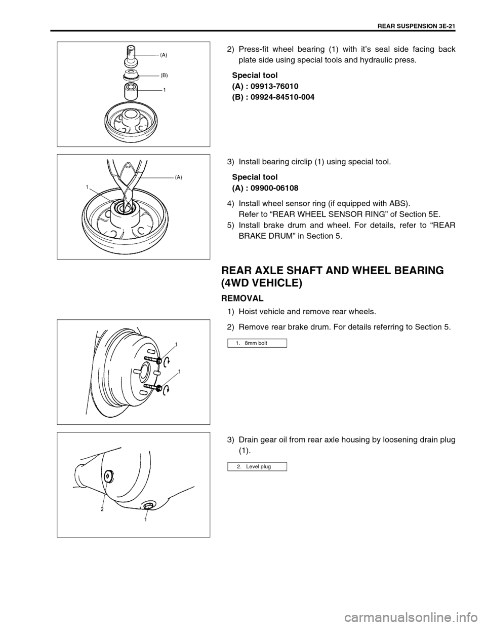
2) Press-fit wheel bearing (1) with it’s seal side facing back
plate side using special tools and hydraulic press.
Special tool
(A) : 09913-76010
(B) : 09924-84510-004
3) Install bearing circlip (1) using special tool.
Special tool
(A) : 09900-06108
4) Install wheel sensor ring (if equipped with ABS).
Refer to “REAR WHEEL SENSOR RING” of Section 5E.
5) Install brake drum and wheel. For details, refer to “REAR
BRAKE DRUM” in Section 5.
REAR AXLE SHAFT AND WHEEL BEARING
(4WD VEHICLE)
REMOVAL
1) Hoist vehicle and remove rear wheels.
2) Remove rear brake drum. For details referring to Section 5.
3) Drain gear oil from rear axle housing by loosening drain plug
(1).
1. 8mm bolt
2. Level plug
Page 235 of 698
3E-22 REAR SUSPENSION
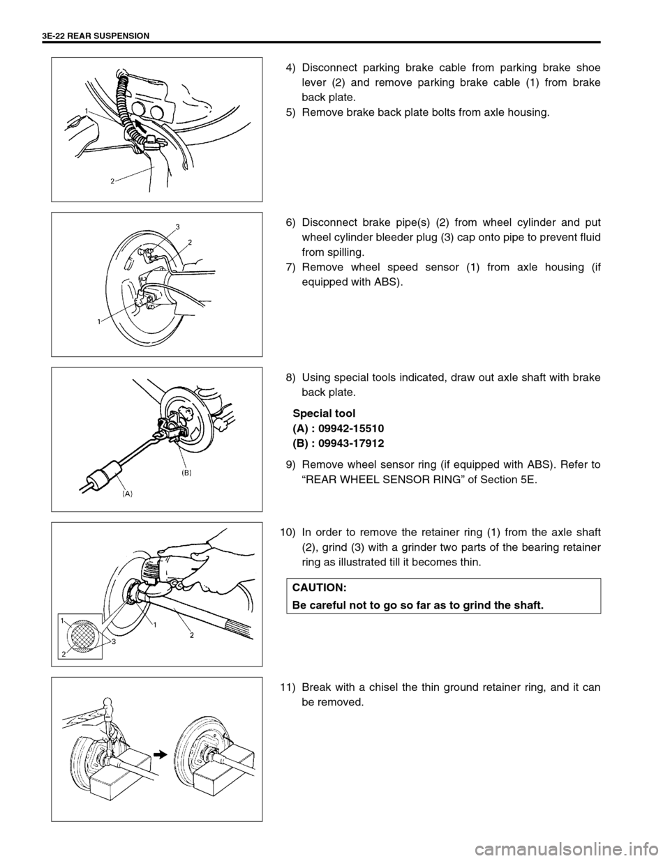
4) Disconnect parking brake cable from parking brake shoe
lever (2) and remove parking brake cable (1) from brake
back plate.
5) Remove brake back plate bolts from axle housing.
6) Disconnect brake pipe(s) (2) from wheel cylinder and put
wheel cylinder bleeder plug (3) cap onto pipe to prevent fluid
from spilling.
7) Remove wheel speed sensor (1) from axle housing (if
equipped with ABS).
8) Using special tools indicated, draw out axle shaft with brake
back plate.
Special tool
(A) : 09942-15510
(B) : 09943-17912
9) Remove wheel sensor ring (if equipped with ABS). Refer to
“REAR WHEEL SENSOR RING” of Section 5E.
10) In order to remove the retainer ring (1) from the axle shaft
(2), grind (3) with a grinder two parts of the bearing retainer
ring as illustrated till it becomes thin.
11) Break with a chisel the thin ground retainer ring, and it can
be removed.
CAUTION:
Be careful not to go so far as to grind the shaft.