ecu SUZUKI SWIFT 2000 1.G RG413 Service Owner's Manual
[x] Cancel search | Manufacturer: SUZUKI, Model Year: 2000, Model line: SWIFT, Model: SUZUKI SWIFT 2000 1.GPages: 698, PDF Size: 16.01 MB
Page 243 of 698
3E-30 REAR SUSPENSION
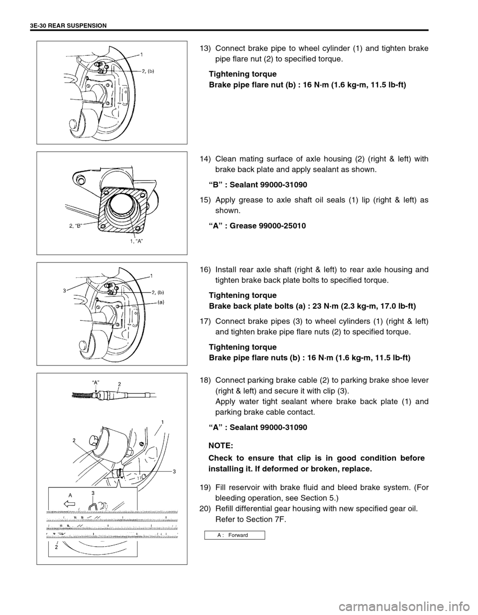
13) Connect brake pipe to wheel cylinder (1) and tighten brake
pipe flare nut (2) to specified torque.
Tightening torque
Brake pipe flare nut (b) : 16 N·m (1.6 kg-m, 11.5 lb-ft)
14) Clean mating surface of axle housing (2) (right & left) with
brake back plate and apply sealant as shown.
“B” : Sealant 99000-31090
15) Apply grease to axle shaft oil seals (1) lip (right & left) as
shown.
“A” : Grease 99000-25010
16) Install rear axle shaft (right & left) to rear axle housing and
tighten brake back plate bolts to specified torque.
Tightening torque
Brake back plate bolts (a) : 23 N·m (2.3 kg-m, 17.0 lb-ft)
17) Connect brake pipes (3) to wheel cylinders (1) (right & left)
and tighten brake pipe flare nuts (2) to specified torque.
Tightening torque
Brake pipe flare nuts (b) : 16 N·m (1.6 kg-m, 11.5 lb-ft)
18) Connect parking brake cable (2) to parking brake shoe lever
(right & left) and secure it with clip (3).
Apply water tight sealant where brake back plate (1) and
parking brake cable contact.
“A” : Sealant 99000-31090
19) Fill reservoir with brake fluid and bleed brake system. (For
bleeding operation, see Section 5.)
20) Refill differential gear housing with new specified gear oil.
Refer to Section 7F.
NOTE:
Check to ensure that clip is in good condition before
installing it. If deformed or broken, replace.
A : Forward
Page 248 of 698
WHEELS AND TIRES 3F-3
HOW TO MEASURE WHEEL RUNOUT
To measure the wheel runout, it is necessary to use an accurate
dial indicator. The tire may be on or off the wheel. The wheel
should be installed to the wheel balancer of the like for proper
measurement.
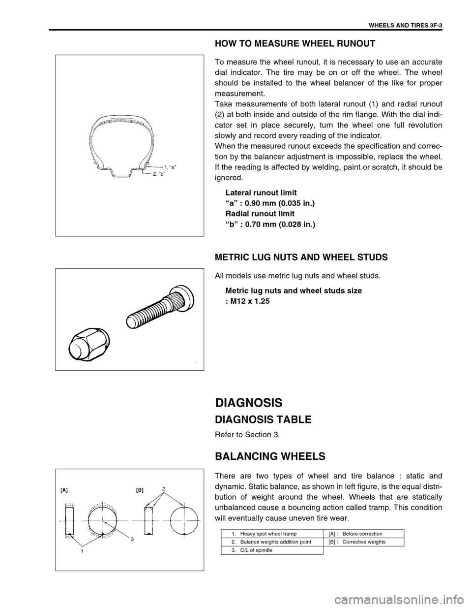
Take measurements of both lateral runout (1) and radial runout
(2) at both inside and outside of the rim flange. With the dial indi-
cator set in place securely, turn the wheel one full revolution
slowly and record every reading of the indicator.
When the measured runout exceeds the specification and correc-
tion by the balancer adjustment is impossible, replace the wheel.
If the reading is affected by welding, paint or scratch, it should be
ignored.
Lateral runout limit
“a” : 0.90 mm (0.035 in.)
Radial runout limit
“b” : 0.70 mm (0.028 in.)
METRIC LUG NUTS AND WHEEL STUDS
All models use metric lug nuts and wheel studs.
Metric lug nuts and wheel studs size
: M12 x 1.25
DIAGNOSIS
DIAGNOSIS TABLE
Refer to Section 3.
BALANCING WHEELS
There are two types of wheel and tire balance : static and
dynamic. Static balance, as shown in left figure, is the equal distri-
bution of weight around the wheel. Wheels that are statically
unbalanced cause a bouncing action called tramp. This condition
will eventually cause uneven tire wear.
1. Heavy spot wheel tramp [A] : Before correction
2. Balance weights addition point [B] : Corrective weights
3. C/L of spindle
Page 266 of 698
FRONT DRIVE SHAFT 4A-13
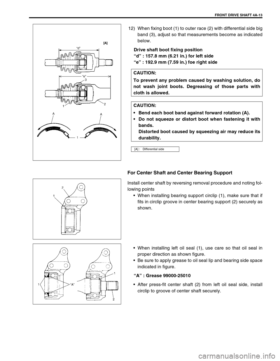
12) When fixing boot (1) to outer race (2) with differential side big
band (3), adjust so that measurements become as indicated
below.
Drive shaft boot fixing position
“d” : 157.8 mm (6.21 in.) for left side
“e” : 192.9 mm (7.59 in.) foe right side
For Center Shaft and Center Bearing Support
Install center shaft by reversing removal procedure and noting fol-
lowing points
When installing bearing support circlip (1), make sure that if
fits in circlip groove in center bearing support (2) securely as
shown.
When installing left oil seal (1), use care so that oil seal in
proper direction as shown figure.
Be sure to apply grease to oil seal lip and bearing side space
indicated in figure.
“A” : Grease 99000-25010
After press-fit center shaft (2) from left oil seal side, install
circlip to groove of center shaft securely. CAUTION:
To prevent any problem caused by washing solution, do
not wash joint boots. Degreasing of those parts with
cloth is allowed.
CAUTION:
Bend each boot band against forward rotation (A).
Do not squeeze or distort boot when fastening it with
bands.
Distorted boot caused by squeezing air may reduce its
durability.
[A] : Differential side
Page 279 of 698
5-6 BRAKES
Excessive pedal travel
(Pedal stroke too
large)Partial brake system failure Check brake systems and repair as
necessary.
Insufficient fluid in master cylinder reservoirs Fill reservoirs with approved brake
fluid.
Check for leaks and air in brake
system.
Check warning light. Bleed system
if required.
Air in system (soft/spongy pedal) Bleed system.
Rear brake system not adjusted
(malfunctioning auto adjusting mechanism)Repair auto adjusting mechanism.
Adjust rear brakes.
Bent brake shoes Replace brake shoes.
Worn rear brake shoes Replace brake shoes.
Brake locked
(For vehicle equipped
with ABS)Malfunctioning ABS Check system referring to Section
5E1.
Dragging brakes
(A very light drag is
present in all brakes
immediately after
pedal is released)Master cylinder pistons not returning correctly Replace master cylinder.
Restricted brake pipes or hoses Check for soft hoses or damaged
pipes and replace with new hoses
and/or new double-walled steel
brake piping.
Incorrect parking brake adjustment on rear
brakesCheck and adjust to correct specifi-
cations.
Weakened or broken return springs in the brake Replace.
Sluggish parking brake cables or linkage Repair or replace.
Wheel cylinder or caliper piston sticking Repair as necessary.
Badly worn piston seal in caliper Replace piston seal.
Pedal pulsation
(Pedal pulsates when
depressed for brak-
ing)Damaged or loose wheel bearings Replace wheel bearings.
Distorted steering knuckle or rear wheel spindle Replace knuckle or rear wheel spin-
dle.
Excessive disc lateral runout Check per instructions. If not within
specifications, replace or machine
disc.
Parallelism between pad and disc not within
specificationsCheck per instructions. If not within
specifications, replace or machine
disc.
Rear drums out of round Check runout.
Repair or replace drum as neces-
sary.
Braking noise
Glazed shoe linings, or foreign matters stuck to
liningsRepair or replace shoe linings.
Worn or distorted shoe linings Replace shoe lining (or pad).
Loose front wheel bearings Replace wheel bearing.
Distorted backing plates or loose mounting
boltsReplace or retighten securing bolts.
Contact wear indicator to brake disc Replace pads. Condition Possible Cause Correction
Page 294 of 698
BRAKES 5-21
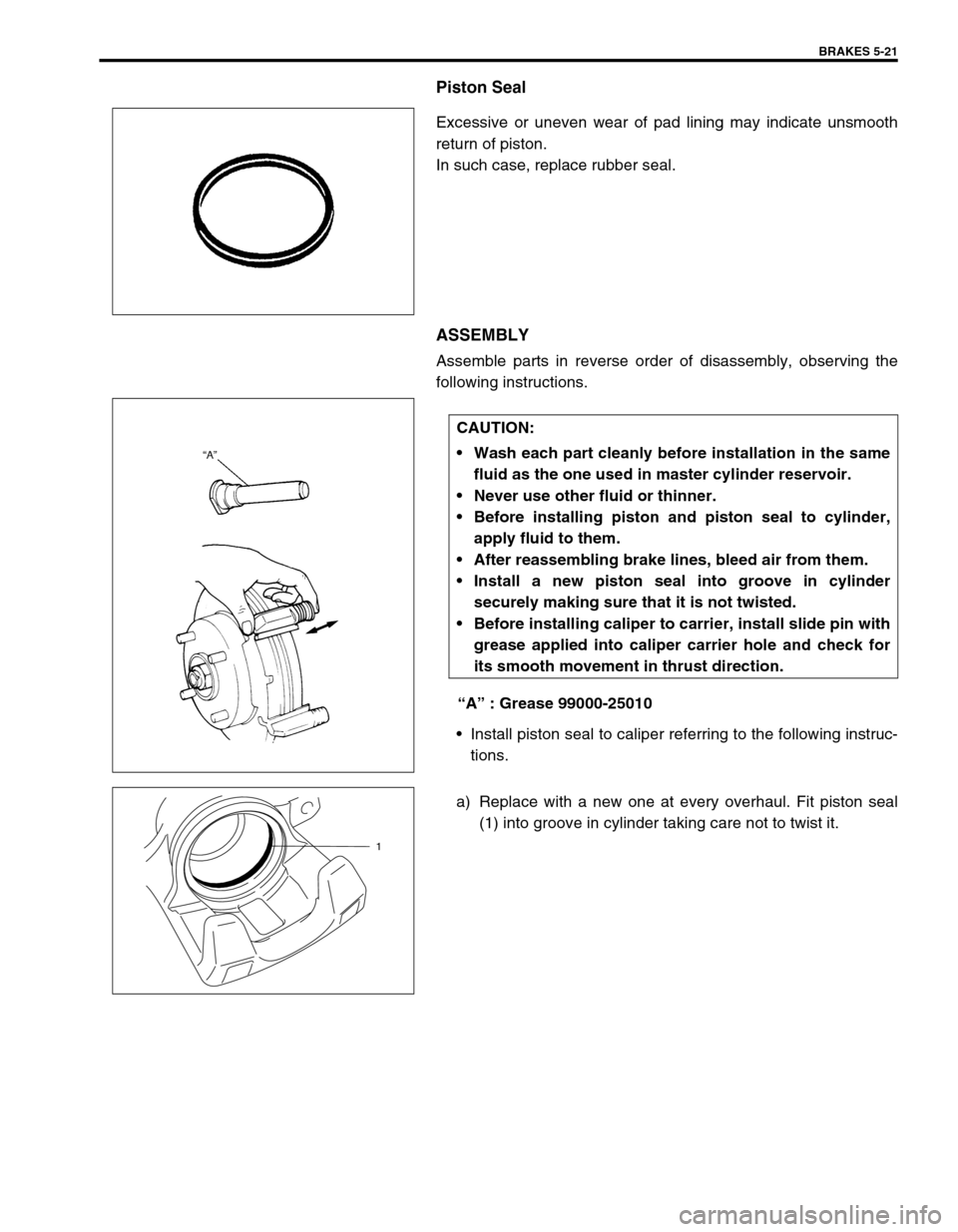
Piston Seal
Excessive or uneven wear of pad lining may indicate unsmooth
return of piston.
In such case, replace rubber seal.
ASSEMBLY
Assemble parts in reverse order of disassembly, observing the
following instructions.
“A” : Grease 99000-25010
Install piston seal to caliper referring to the following instruc-
tions.
a) Replace with a new one at every overhaul. Fit piston seal
(1) into groove in cylinder taking care not to twist it.
CAUTION:
Wash each part cleanly before installation in the same
fluid as the one used in master cylinder reservoir.
Never use other fluid or thinner.
Before installing piston and piston seal to cylinder,
apply fluid to them.
After reassembling brake lines, bleed air from them.
Install a new piston seal into groove in cylinder
securely making sure that it is not twisted.
Before installing caliper to carrier, install slide pin with
grease applied into caliper carrier hole and check for
its smooth movement in thrust direction.
1
Page 295 of 698
5-22 BRAKES
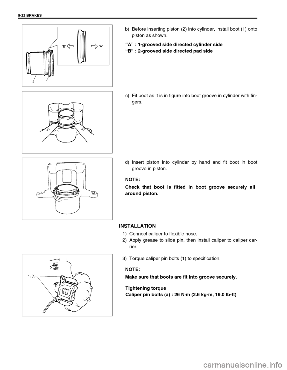
b) Before inserting piston (2) into cylinder, install boot (1) onto
piston as shown.
“A” : 1-grooved side directed cylinder side
“B” : 2-grooved side directed pad side
c) Fit boot as it is in figure into boot groove in cylinder with fin-
gers.
d) Insert piston into cylinder by hand and fit boot in boot
groove in piston.
INSTALLATION
1) Connect caliper to flexible hose.
2) Apply grease to slide pin, then install caliper to caliper car-
rier.
3) Torque caliper pin bolts (1) to specification.
Tightening torque
Caliper pin bolts (a) : 26 N·m (2.6 kg-m, 19.0 Ib-ft)
“A”
“B”
NOTE:
Check that boot is fitted in boot groove securely all
around piston.
NOTE:
Make sure that boots are fit into groove securely.
Page 296 of 698
BRAKES 5-23
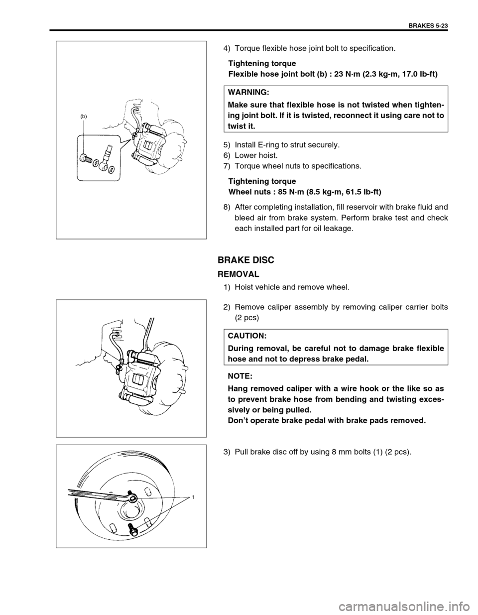
4) Torque flexible hose joint bolt to specification.
Tightening torque
Flexible hose joint bolt (b) : 23 N·m (2.3 kg-m, 17.0 Ib-ft)
5) Install E-ring to strut securely.
6) Lower hoist.
7) Torque wheel nuts to specifications.
Tightening torque
Wheel nuts : 85 N·m (8.5 kg-m, 61.5 Ib-ft)
8) After completing installation, fill reservoir with brake fluid and
bleed air from brake system. Perform brake test and check
each installed part for oil leakage.
BRAKE DISC
REMOVAL
1) Hoist vehicle and remove wheel.
2) Remove caliper assembly by removing caliper carrier bolts
(2 pcs)
3) Pull brake disc off by using 8 mm bolts (1) (2 pcs).WARNING:
Make sure that flexible hose is not twisted when tighten-
ing joint bolt. If it is twisted, reconnect it using care not to
twist it.
CAUTION:
During removal, be careful not to damage brake flexible
hose and not to depress brake pedal.
NOTE:
Hang removed caliper with a wire hook or the like so as
to prevent brake hose from bending and twisting exces-
sively or being pulled.
Don’t operate brake pedal with brake pads removed.
Page 304 of 698
BRAKES 5-31
INSTALLATION
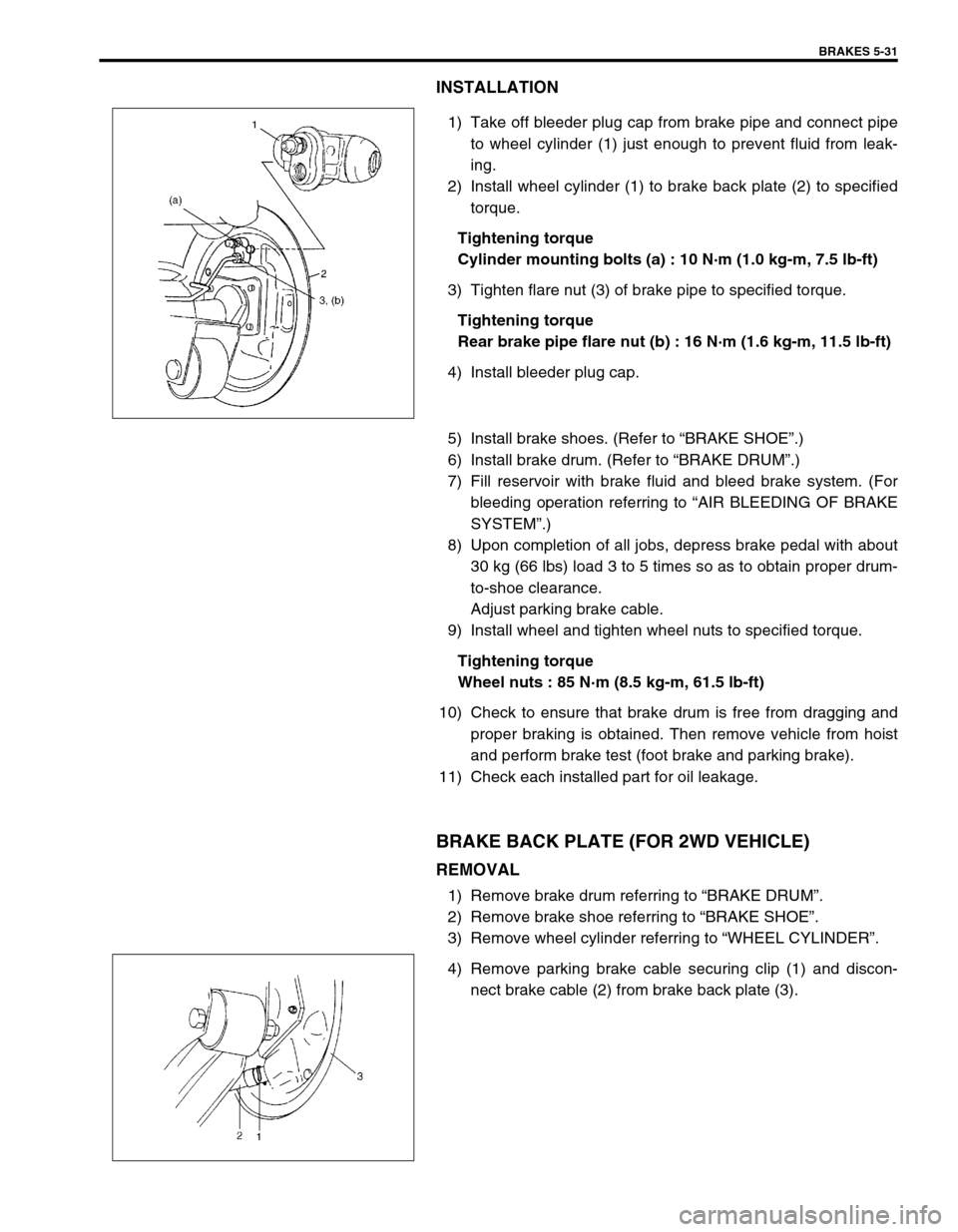
1) Take off bleeder plug cap from brake pipe and connect pipe
to wheel cylinder (1) just enough to prevent fluid from leak-
ing.
2) Install wheel cylinder (1) to brake back plate (2) to specified
torque.
Tightening torque
Cylinder mounting bolts (a) : 10 N·m (1.0 kg-m, 7.5 lb-ft)
3) Tighten flare nut (3) of brake pipe to specified torque.
Tightening torque
Rear brake pipe flare nut (b) : 16 N·m (1.6 kg-m, 11.5 lb-ft)
4) Install bleeder plug cap.
5) Install brake shoes. (Refer to “BRAKE SHOE”.)
6) Install brake drum. (Refer to “BRAKE DRUM”.)
7) Fill reservoir with brake fluid and bleed brake system. (For
bleeding operation referring to “AIR BLEEDING OF BRAKE
SYSTEM”.)
8) Upon completion of all jobs, depress brake pedal with about
30 kg (66 lbs) load 3 to 5 times so as to obtain proper drum-
to-shoe clearance.
Adjust parking brake cable.
9) Install wheel and tighten wheel nuts to specified torque.
Tightening torque
Wheel nuts : 85 N·m (8.5 kg-m, 61.5 lb-ft)
10) Check to ensure that brake drum is free from dragging and
proper braking is obtained. Then remove vehicle from hoist
and perform brake test (foot brake and parking brake).
11) Check each installed part for oil leakage.
BRAKE BACK PLATE (FOR 2WD VEHICLE)
REMOVAL
1) Remove brake drum referring to “BRAKE DRUM”.
2) Remove brake shoe referring to “BRAKE SHOE”.
3) Remove wheel cylinder referring to “WHEEL CYLINDER”.
4) Remove parking brake cable securing clip (1) and discon-
nect brake cable (2) from brake back plate (3).
Page 305 of 698
5-32 BRAKES
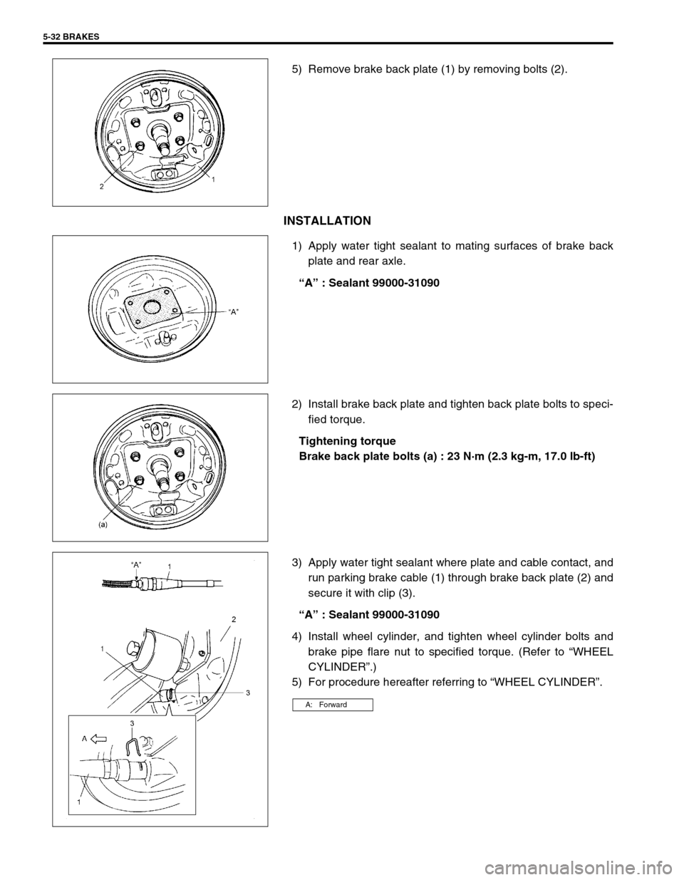
5) Remove brake back plate (1) by removing bolts (2).
INSTALLATION
1) Apply water tight sealant to mating surfaces of brake back
plate and rear axle.
“A” : Sealant 99000-31090
2) Install brake back plate and tighten back plate bolts to speci-
fied torque.
Tightening torque
Brake back plate bolts (a) : 23 N·m (2.3 kg-m, 17.0 lb-ft)
3) Apply water tight sealant where plate and cable contact, and
run parking brake cable (1) through brake back plate (2) and
secure it with clip (3).
“A” : Sealant 99000-31090
4) Install wheel cylinder, and tighten wheel cylinder bolts and
brake pipe flare nut to specified torque. (Refer to “WHEEL
CYLINDER”.)
5) For procedure hereafter referring to “WHEEL CYLINDER”.
A: Forward
Page 308 of 698
BRAKES 5-35
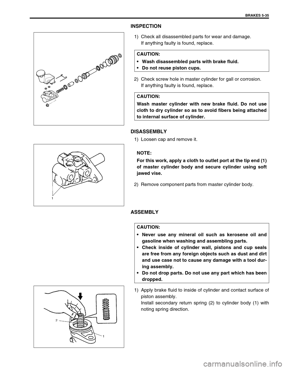
INSPECTION
1) Check all disassembled parts for wear and damage.
If anything faulty is found, replace.
2) Check screw hole in master cylinder for gall or corrosion.
If anything faulty is found, replace.
DISASSEMBLY
1) Loosen cap and remove it.
2) Remove component parts from master cylinder body.
ASSEMBLY
1) Apply brake fluid to inside of cylinder and contact surface of
piston assembly.
Install secondary return spring (2) to cylinder body (1) with
noting spring direction. CAUTION:
Wash disassembled parts with brake fluid.
Do not reuse piston cups.
CAUTION:
Wash master cylinder with new brake fluid. Do not use
cloth to dry cylinder so as to avoid fibers being attached
to internal surface of cylinder.
NOTE:
For this work, apply a cloth to outlet port at the tip end (1)
of master cylinder body and secure cylinder using soft
jawed vise.
CAUTION:
Never use any mineral oil such as kerosene oil and
gasoline when washing and assembling parts.
Check inside of cylinder wall, pistons and cup seals
are free from any foreign objects such as dust and dirt
and use case not to cause any damage with a tool dur-
ing assembly.
Do not drop parts. Do not use any part which has been
dropped.