ecu SUZUKI SWIFT 2000 1.G RG413 Service Owner's Guide
[x] Cancel search | Manufacturer: SUZUKI, Model Year: 2000, Model line: SWIFT, Model: SUZUKI SWIFT 2000 1.GPages: 698, PDF Size: 16.01 MB
Page 334 of 698
ANTILOCK BRAKE SYSTEM (ABS) 5E-9
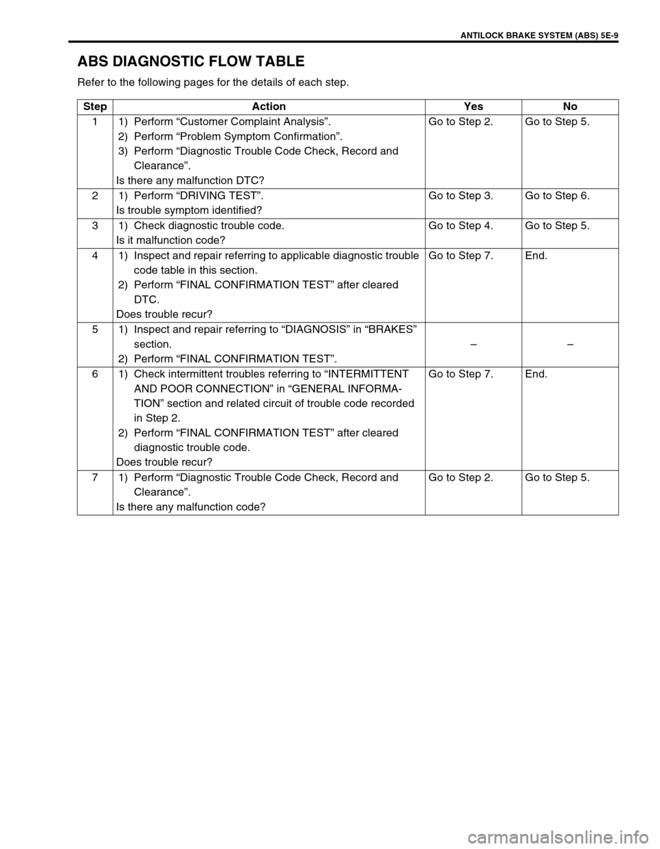
ABS DIAGNOSTIC FLOW TABLE
Refer to the following pages for the details of each step.
Step Action Yes No
11)Perform “Customer Complaint Analysis”.
2) Perform “Problem Symptom Confirmation”.
3) Perform “Diagnostic Trouble Code Check, Record and
Clearance”.
Is there any malfunction DTC?Go to Step 2. Go to Step 5.
21)Perform “DRIVING TEST”.
Is trouble symptom identified?Go to Step 3. Go to Step 6.
3 1) Check diagnostic trouble code.
Is it malfunction code?Go to Step 4. Go to Step 5.
4 1) Inspect and repair referring to applicable diagnostic trouble
code table in this section.
2) Perform “FINAL CONFIRMATION TEST” after cleared
DTC.
Does trouble recur?Go to Step 7. End.
5 1) Inspect and repair referring to “DIAGNOSIS” in “BRAKES”
section.
2) Perform “FINAL CONFIRMATION TEST”.––
6 1) Check intermittent troubles referring to “INTERMITTENT
AND POOR CONNECTION” in “GENERAL INFORMA-
TION” section and related circuit of trouble code recorded
in Step 2.
2) Perform “FINAL CONFIRMATION TEST” after cleared
diagnostic trouble code.
Does trouble recur?Go to Step 7. End.
71)Perform “Diagnostic Trouble Code Check, Record and
Clearance”.
Is there any malfunction code?Go to Step 2. Go to Step 5.
Page 341 of 698
5E-16 ANTILOCK BRAKE SYSTEM (ABS)
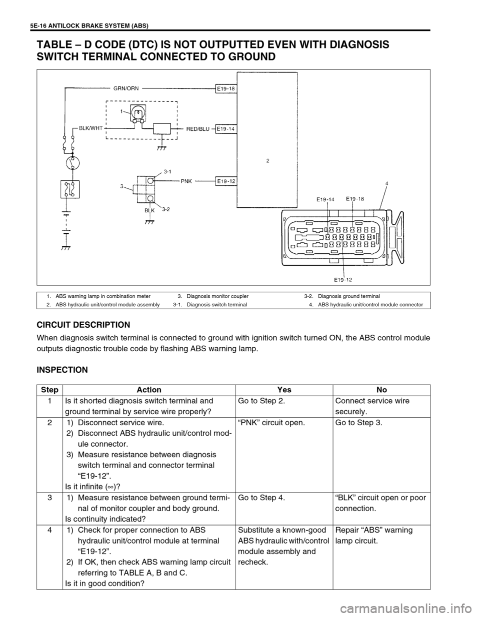
TABLE – D CODE (DTC) IS NOT OUTPUTTED EVEN WITH DIAGNOSIS
SWITCH TERMINAL CONNECTED TO GROUND
CIRCUIT DESCRIPTION
When diagnosis switch terminal is connected to ground with ignition switch turned ON, the ABS control module
outputs diagnostic trouble code by flashing ABS warning lamp.
INSPECTION
1. ABS warning lamp in combination meter 3. Diagnosis monitor coupler 3-2. Diagnosis ground terminal
2. ABS hydraulic unit/control module assembly 3-1. Diagnosis switch terminal 4. ABS hydraulic unit/control module connector
Step Action Yes No
1 Is it shorted diagnosis switch terminal and
ground terminal by service wire properly?Go to Step 2. Connect service wire
securely.
2 1) Disconnect service wire.
2) Disconnect ABS hydraulic unit/control mod-
ule connector.
3) Measure resistance between diagnosis
switch terminal and connector terminal
“E19-12”.
Is it infinite (∞)?“PNK” circuit open. Go to Step 3.
3 1) Measure resistance between ground termi-
nal of monitor coupler and body ground.
Is continuity indicated?Go to Step 4.“BLK” circuit open or poor
connection.
4 1) Check for proper connection to ABS
hydraulic unit/control module at terminal
“E19-12”.
2) If OK, then check ABS warning lamp circuit
referring to TABLE A, B and C.
Is it in good condition?Substitute a known-good
ABS hydraulic with/control
module assembly and
recheck.Repair “ABS” warning
lamp circuit.
Page 348 of 698
ANTILOCK BRAKE SYSTEM (ABS) 5E-23
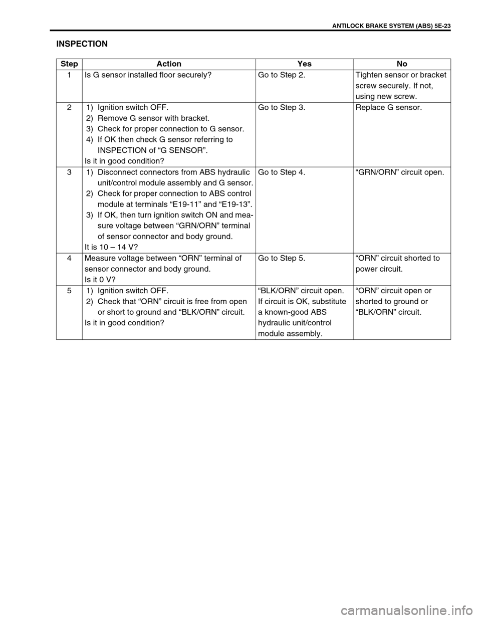
INSPECTION
Step Action Yes No
1 Is G sensor installed floor securely? Go to Step 2. Tighten sensor or bracket
screw securely. If not,
using new screw.
2 1) Ignition switch OFF.
2) Remove G sensor with bracket.
3) Check for proper connection to G sensor.
4) If OK then check G sensor referring to
INSPECTION of “G SENSOR”.
Is it in good condition?Go to Step 3. Replace G sensor.
3 1) Disconnect connectors from ABS hydraulic
unit/control module assembly and G sensor.
2) Check for proper connection to ABS control
module at terminals “E19-11” and “E19-13”.
3) If OK, then turn ignition switch ON and mea-
sure voltage between “GRN/ORN” terminal
of sensor connector and body ground.
It is 10 – 14 V?Go to Step 4.“GRN/ORN” circuit open.
4 Measure voltage between “ORN” terminal of
sensor connector and body ground.
Is it 0 V?Go to Step 5.“ORN” circuit shorted to
power circuit.
5 1) Ignition switch OFF.
2) Check that “ORN” circuit is free from open
or short to ground and “BLK/ORN” circuit.
Is it in good condition?“BLK/ORN” circuit open.
If circuit is OK, substitute
a known-good ABS
hydraulic unit/control
module assembly.“ORN” circuit open or
shorted to ground or
“BLK/ORN” circuit.
Page 368 of 698
ANTILOCK BRAKE SYSTEM (ABS) 5E-43
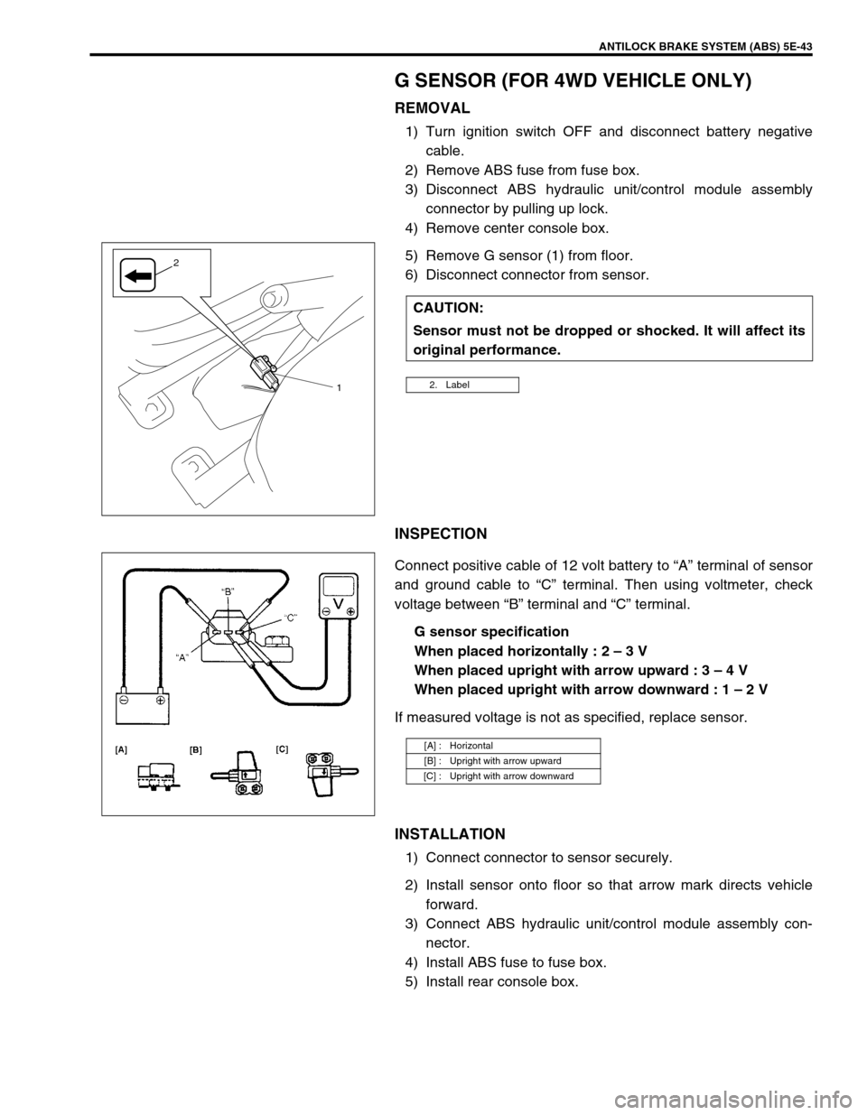
G SENSOR (FOR 4WD VEHICLE ONLY)
REMOVAL
1) Turn ignition switch OFF and disconnect battery negative
cable.
2) Remove ABS fuse from fuse box.
3) Disconnect ABS hydraulic unit/control module assembly
connector by pulling up lock.
4) Remove center console box.
5) Remove G sensor (1) from floor.
6) Disconnect connector from sensor.
INSPECTION
Connect positive cable of 12 volt battery to “A” terminal of sensor
and ground cable to “C” terminal. Then using voltmeter, check
voltage between “B” terminal and “C” terminal.
G sensor specification
When placed horizontally : 2 – 3 V
When placed upright with arrow upward : 3 – 4 V
When placed upright with arrow downward : 1 – 2 V
If measured voltage is not as specified, replace sensor.
INSTALLATION
1) Connect connector to sensor securely.
2) Install sensor onto floor so that arrow mark directs vehicle
forward.
3) Connect ABS hydraulic unit/control module assembly con-
nector.
4) Install ABS fuse to fuse box.
5) Install rear console box.CAUTION:
Sensor must not be dropped or shocked. It will affect its
original performance.
2. Label1
2
[A] : Horizontal
[B] : Upright with arrow upward
[C] : Upright with arrow downward
Page 374 of 698
ENGINE GENERAL INFORMATION AND DIAGNOSIS 6-5
PRECAUTION ON FUEL SYSTEM SERVICE
Work must be done with no smoking, in a well-ventilated
area and away from any open flames.
As fuel feed line (between fuel pump and fuel delivery pipe)
is still under high fuel pressure even after engine was
stopped, loosening or disconnecting fuel feed line directly
may cause dangerous spout of fuel to occur where loosened
or disconnected.
Before loosening or disconnecting fuel feed line, make sure
to release fuel pressure according to “FUEL PRESSURE
RELIEF PROCEDURE”. A small amount of fuel may be
released after the fuel line is disconnected. In order to
reduce the chance of personal injury, cover the fitting to be
disconnected with a shop cloth. Put that cloth in an approved
container when disconnection is completed.
Never run engine with fuel pump relay disconnected when
engine and exhaust system are hot.
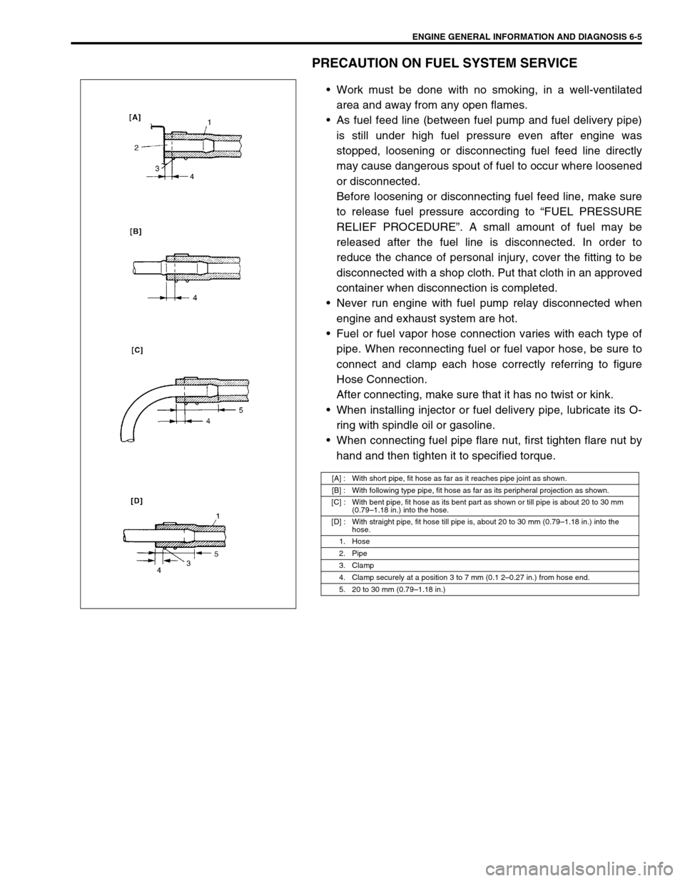
Fuel or fuel vapor hose connection varies with each type of
pipe. When reconnecting fuel or fuel vapor hose, be sure to
connect and clamp each hose correctly referring to figure
Hose Connection.
After connecting, make sure that it has no twist or kink.
When installing injector or fuel delivery pipe, lubricate its O-
ring with spindle oil or gasoline.
When connecting fuel pipe flare nut, first tighten flare nut by
hand and then tighten it to specified torque.
[A] : With short pipe, fit hose as far as it reaches pipe joint as shown.
[B] : With following type pipe, fit hose as far as its peripheral projection as shown.
[C] : With bent pipe, fit hose as its bent part as shown or till pipe is about 20 to 30 mm
(0.79–1.18 in.) into the hose.
[D] : With straight pipe, fit hose till pipe is, about 20 to 30 mm (0.79–1.18 in.) into the
hose.
1. Hose
2. Pipe
3. Clamp
4. Clamp securely at a position 3 to 7 mm (0.1 2–0.27 in.) from hose end.
5. 20 to 30 mm (0.79–1.18 in.)
Page 375 of 698
6-6 ENGINE GENERAL INFORMATION AND DIAGNOSIS
FUEL PRESSURE RELIEF PROCEDURE
After making sure that engine is cold, release fuel pressure as fol-
lows.
1) Place transmission gear shift lever in “Neutral” (Shift selector
lever to “P” range for A/T model), set parking brake, and
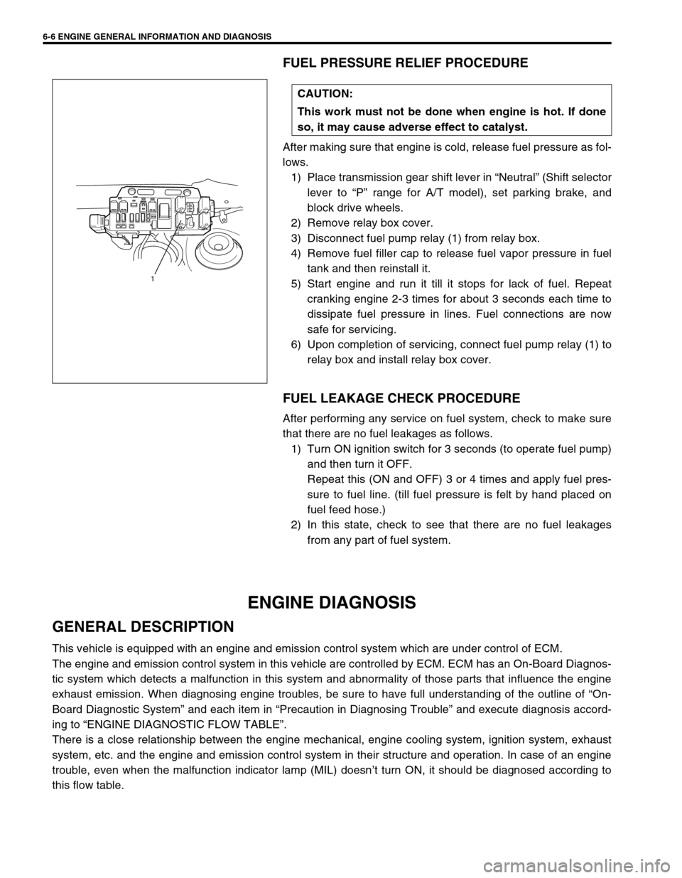
block drive wheels.
2) Remove relay box cover.
3) Disconnect fuel pump relay (1) from relay box.
4) Remove fuel filler cap to release fuel vapor pressure in fuel
tank and then reinstall it.
5) Start engine and run it till it stops for lack of fuel. Repeat
cranking engine 2-3 times for about 3 seconds each time to
dissipate fuel pressure in lines. Fuel connections are now
safe for servicing.
6) Upon completion of servicing, connect fuel pump relay (1) to
relay box and install relay box cover.
FUEL LEAKAGE CHECK PROCEDURE
After performing any service on fuel system, check to make sure
that there are no fuel leakages as follows.
1) Turn ON ignition switch for 3 seconds (to operate fuel pump)
and then turn it OFF.
Repeat this (ON and OFF) 3 or 4 times and apply fuel pres-
sure to fuel line. (till fuel pressure is felt by hand placed on
fuel feed hose.)
2) In this state, check to see that there are no fuel leakages
from any part of fuel system.
ENGINE DIAGNOSIS
GENERAL DESCRIPTION
This vehicle is equipped with an engine and emission control system which are under control of ECM.
The engine and emission control system in this vehicle are controlled by ECM. ECM has an On-Board Diagnos-
tic system which detects a malfunction in this system and abnormality of those parts that influence the engine
exhaust emission. When diagnosing engine troubles, be sure to have full understanding of the outline of “On-
Board Diagnostic System” and each item in “Precaution in Diagnosing Trouble” and execute diagnosis accord-
ing to “ENGINE DIAGNOSTIC FLOW TABLE”.
There is a close relationship between the engine mechanical, engine cooling system, ignition system, exhaust
system, etc. and the engine and emission control system in their structure and operation. In case of an engine
trouble, even when the malfunction indicator lamp (MIL) doesn’t turn ON, it should be diagnosed according to
this flow table.CAUTION:
This work must not be done when engine is hot. If done
so, it may cause adverse effect to catalyst.
1
Page 389 of 698
6-20 ENGINE GENERAL INFORMATION AND DIAGNOSIS
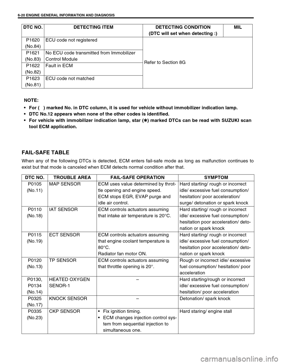
FAIL-SAFE TABLE
When any of the following DTCs is detected, ECM enters fail-safe mode as long as malfunction continues to
exist but that mode is canceled when ECM detects normal condition after that.P1620
(No.84)ECU code not registered
Refer to Section 8G P1621
(No.83)No ECU code transmitted from Immobilizer
Control Module
P1622
(No.82)Fault in ECM
P1623
(No.81)ECU code not matched DTC NO. DETECTING ITEM DETECTING CONDITION
(DTC will set when detecting :)MIL
NOTE:
For (
) marked No. in DTC column, it is used for vehicle without immobilizer indication lamp.
DTC No.12 appears when none of the other codes is identified.
For vehicle with immobilizer indication lamp, star (
✱) marked DTCs can be read with SUZUKI scan
tool ECM application.
DTC NO. TROUBLE AREA FAIL-SAFE OPERATION SYMPTOM
P0105
(No.11)MAP SENSOR ECM uses value determined by throt-
tle opening and engine speed.
ECM stops EGR, EVAP purge and
idle air control.Hard starting/ rough or incorrect
idle/ excessive fuel consumption/
hesitation/ poor acceleration/
surge/ detonation or spark knock
P0110
(No.18)IAT SENSOR ECM controls actuators assuming
that intake air temperature is 20°C.Hard starting/ rough or incorrect
idle/ excessive fuel consumption/
hesitation poor acceleration/ deto-
nation or spark knock
P0115
(No.19)ECT SENSOR ECM controls actuators assuming
that engine coolant temperature is
80°C.
Radiator fan motor ON.Hard starting/ rough or incorrect
idle/ excessive fuel consumption/
hesitation poor acceleration/ deto-
nation or spark knock
P0120
(No.13)TP SENSOR ECM controls actuators assuming
that throttle opening is 20°.Rough or incorrect idle/ excessive
fuel consumption/ hesitation/ poor
acceleration
P0130,
P0134
(No.14)HEATED OXYGEN
SENOR-1–Hard starting/rough or incorrect
idle/ excessive fuel consumption/
hesitation/ poor acceleration
P0325
(No.17)KNOCK SENSOR–Detonation/ spark knock
P0335
(No.23)CKP SENSORFix ignition timing.
ECM changes injection control sys-
tem from sequential injection to
simultaneous one.Hard staring/ engine stall
Page 422 of 698
ENGINE GENERAL INFORMATION AND DIAGNOSIS 6-53
MAP SENSOR INDIVIDUAL CHECK
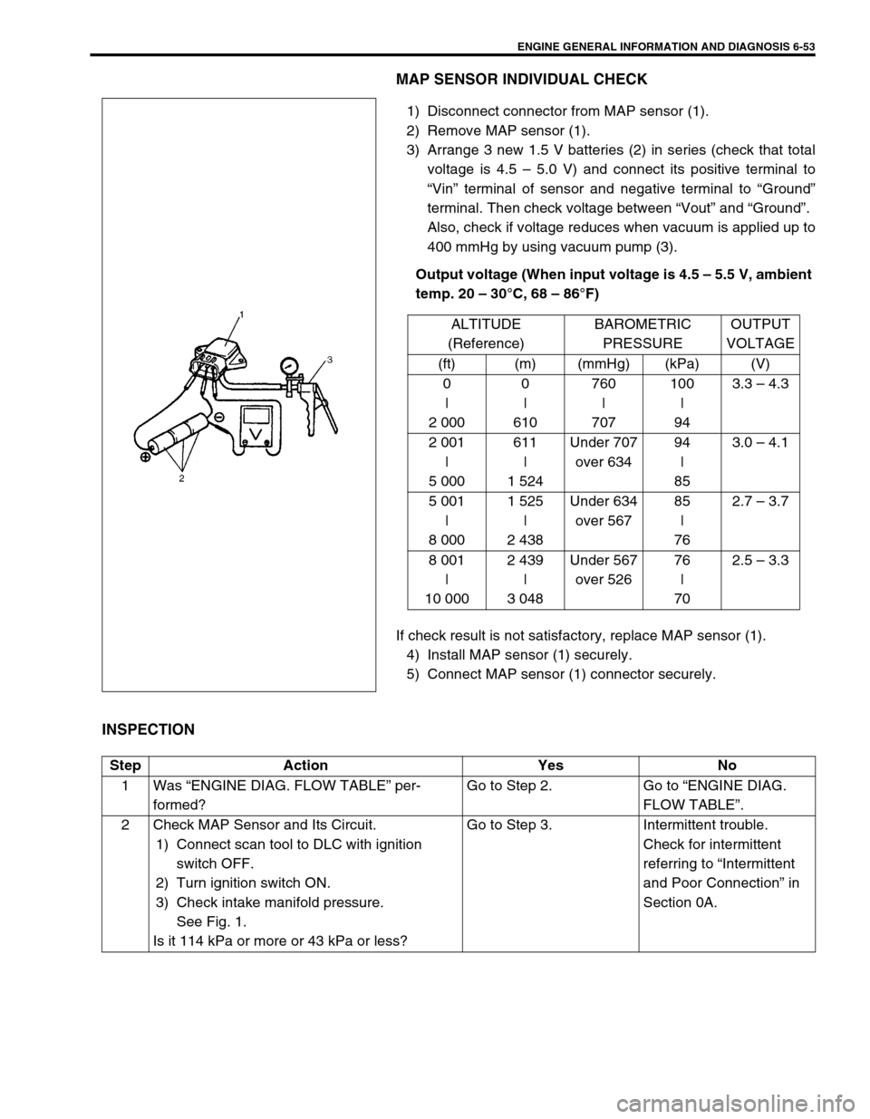
1) Disconnect connector from MAP sensor (1).
2) Remove MAP sensor (1).
3) Arrange 3 new 1.5 V batteries (2) in series (check that total
voltage is 4.5 – 5.0 V) and connect its positive terminal to
“Vin” terminal of sensor and negative terminal to “Ground”
terminal. Then check voltage between “Vout” and “Ground”.
Also, check if voltage reduces when vacuum is applied up to
400 mmHg by using vacuum pump (3).
Output voltage (When input voltage is 4.5 – 5.5 V, ambient
temp. 20 – 30°C, 68 – 86°F)
If check result is not satisfactory, replace MAP sensor (1).
4) Install MAP sensor (1) securely.
5) Connect MAP sensor (1) connector securely.
INSPECTION
ALTITUDE
(Reference)BAROMETRIC
PRESSUREOUTPUT
VOLTAGE
(ft) (m) (mmHg) (kPa) (V)
0
|
2 0000
|
610760
|
707100
|
943.3 – 4.3
2 001
|
5 000611
|
1 524Under 707
over 63494
|
853.0 – 4.1
5 001
|
8 0001 525
|
2 438Under 634
over 56785
|
762.7 – 3.7
8 001
|
10 0002 439
|
3 048Under 567
over 52676
|
702.5 – 3.3
Step Action Yes No
1Was “ENGINE DIAG. FLOW TABLE” per-
formed?Go to Step 2. Go to “ENGINE DIAG.
FLOW TABLE”.
2 Check MAP Sensor and Its Circuit.
1) Connect scan tool to DLC with ignition
switch OFF.
2) Turn ignition switch ON.
3) Check intake manifold pressure.
See Fig. 1.
Is it 114 kPa or more or 43 kPa or less?Go to Step 3. Intermittent trouble.
Check for intermittent
referring to “Intermittent
and Poor Connection” in
Section 0A.
Page 458 of 698
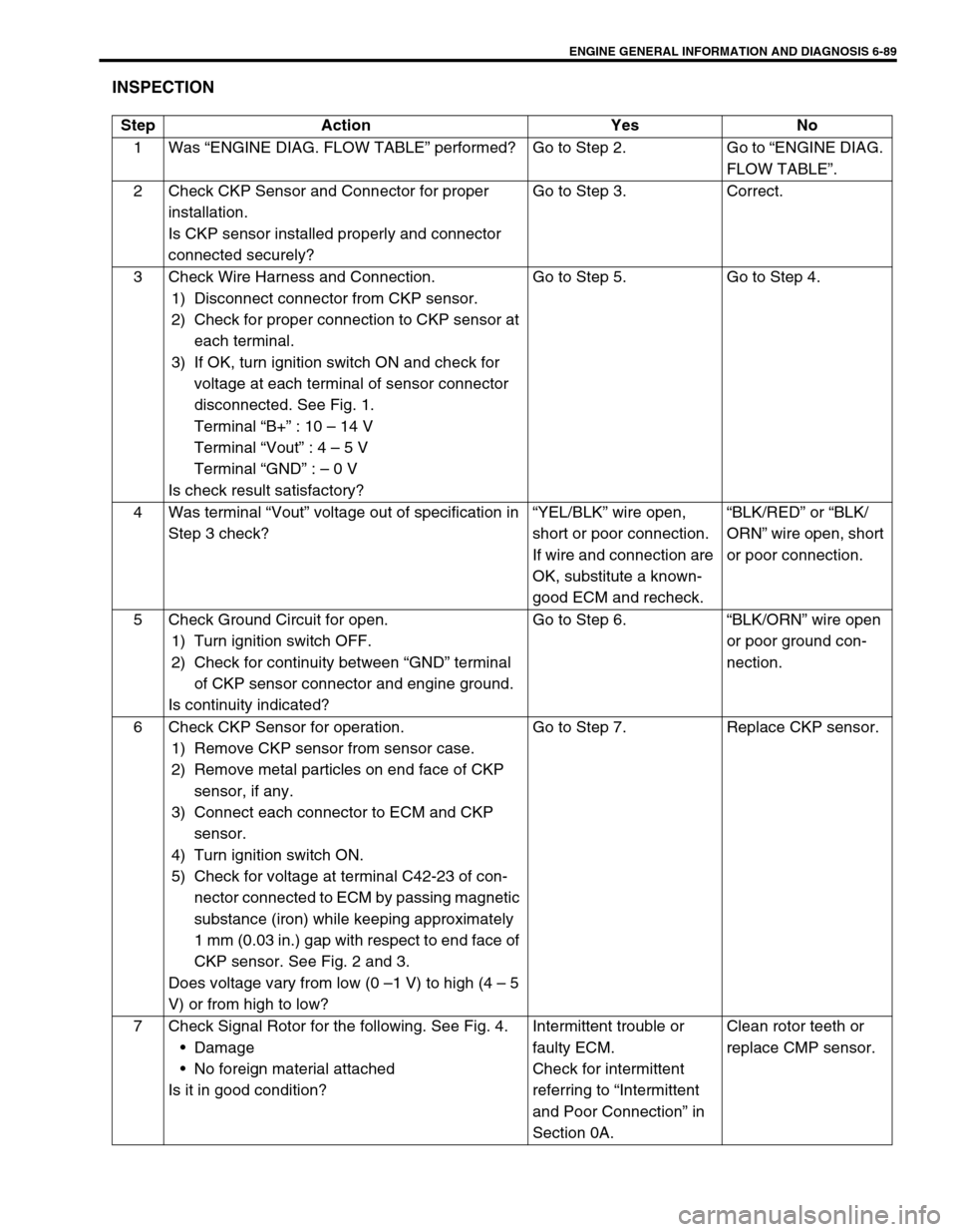
ENGINE GENERAL INFORMATION AND DIAGNOSIS 6-89
INSPECTION
Step Action Yes No
1Was “ENGINE DIAG. FLOW TABLE” performed? Go to Step 2. Go to “ENGINE DIAG.
FLOW TABLE”.
2 Check CKP Sensor and Connector for proper
installation.
Is CKP sensor installed properly and connector
connected securely?Go to Step 3. Correct.
3 Check Wire Harness and Connection.
1) Disconnect connector from CKP sensor.
2) Check for proper connection to CKP sensor at
each terminal.
3) If OK, turn ignition switch ON and check for
voltage at each terminal of sensor connector
disconnected. See Fig. 1.
Terminal “B+” : 10 – 14 V
Terminal “Vout” : 4 – 5 V
Terminal “GND” : – 0 V
Is check result satisfactory?Go to Step 5. Go to Step 4.
4 Was terminal “Vout” voltage out of specification in
Step 3 check?“YEL/BLK” wire open,
short or poor connection.
If wire and connection are
OK, substitute a known-
good ECM and recheck.“BLK/RED” or “BLK/
ORN” wire open, short
or poor connection.
5 Check Ground Circuit for open.
1) Turn ignition switch OFF.
2) Check for continuity between “GND” terminal
of CKP sensor connector and engine ground.
Is continuity indicated?Go to Step 6.“BLK/ORN” wire open
or poor ground con-
nection.
6 Check CKP Sensor for operation.
1) Remove CKP sensor from sensor case.
2) Remove metal particles on end face of CKP
sensor, if any.
3) Connect each connector to ECM and CKP
sensor.
4) Turn ignition switch ON.
5) Check for voltage at terminal C42-23 of con-
nector connected to ECM by passing magnetic
substance (iron) while keeping approximately
1 mm (0.03 in.) gap with respect to end face of
CKP sensor. See Fig. 2 and 3.
Does voltage vary from low (0 –1 V) to high (4 – 5
V) or from high to low?Go to Step 7. Replace CKP sensor.
7 Check Signal Rotor for the following. See Fig. 4.
Damage
No foreign material attached
Is it in good condition?Intermittent trouble or
faulty ECM.
Check for intermittent
referring to “Intermittent
and Poor Connection” in
Section 0A.Clean rotor teeth or
replace CMP sensor.
Page 461 of 698
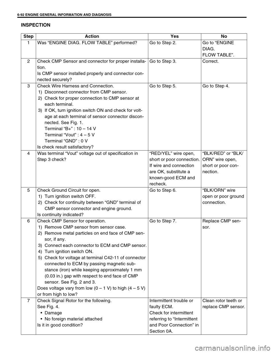
6-92 ENGINE GENERAL INFORMATION AND DIAGNOSIS
INSPECTION
Step Action Yes No
1Was “ENGINE DIAG. FLOW TABLE” performed? Go to Step 2. Go to “ENGINE
DIAG.
FLOW TABLE”.
2 Check CMP Sensor and connector for proper installa-
tion.
Is CMP sensor installed properly and connector con-
nected securely?Go to Step 3. Correct.
3 Check Wire Harness and Connection.
1) Disconnect connector from CMP sensor.
2) Check for proper connection to CMP sensor at
each terminal.
3) If OK, turn ignition switch ON and check for volt-
age at each terminal of sensor connector discon-
nected. See Fig. 1.
Terminal “B+” : 10 – 14 V
Terminal “Vout” : 4 – 5 V
Terminal “GND” : 0 V
Is check result satisfactory?Go to Step 5. Go to Step 4.
4Was terminal “Vout” voltage out of specification in
Step 3 check?“RED/YEL” wire open,
short or poor connection.
If wire and connection
are OK, substitute a
known-good ECM and
recheck.“BLK/RED” or “BLK/
ORN” wire open,
short or poor con-
nection.
5 Check Ground Circuit for open.
1) Turn ignition switch OFF.
2) Check for continuity between “GND” terminal of
CMP sensor connector and engine ground.
Is continuity indicated?Go to Step 6.“BLK/ORN” wire
open or poor ground
connection.
6 Check CMP Sensor for operation.
1) Remove CMP sensor from sensor case.
2) Remove metal particles on end face of CMP sen-
sor, if any.
3) Connect each connector to ECM and CMP sensor.
4) Turn ignition switch ON.
5) Check for voltage at terminal C42-11 of connector
connected to ECM by passing magnetic sub-
stance (iron) while keeping approximately 1 mm
(0.03 in.) gap with respect to end face of CMP
sensor. See Fig. 2 and 3.
Does voltage vary from low (0 – 1 V) to high (4 – 5 V)
or from high to low?Go to Step 7. Replace CMP sen-
sor.
7 Check Signal Rotor for the following.
See Fig. 4.
Damage
No foreign material attached
Is it in good condition?Intermittent trouble or
faulty ECM.
Check for intermittent
referring to “Intermittent
and Poor Connection” in
Section 0A.Clean rotor teeth or
replace CMP sensor.