ecu SUZUKI SWIFT 2000 1.G RG413 Service Service Manual
[x] Cancel search | Manufacturer: SUZUKI, Model Year: 2000, Model line: SWIFT, Model: SUZUKI SWIFT 2000 1.GPages: 698, PDF Size: 16.01 MB
Page 507 of 698
6A1-6 ENGINE MECHANICAL (M13 ENGINE)
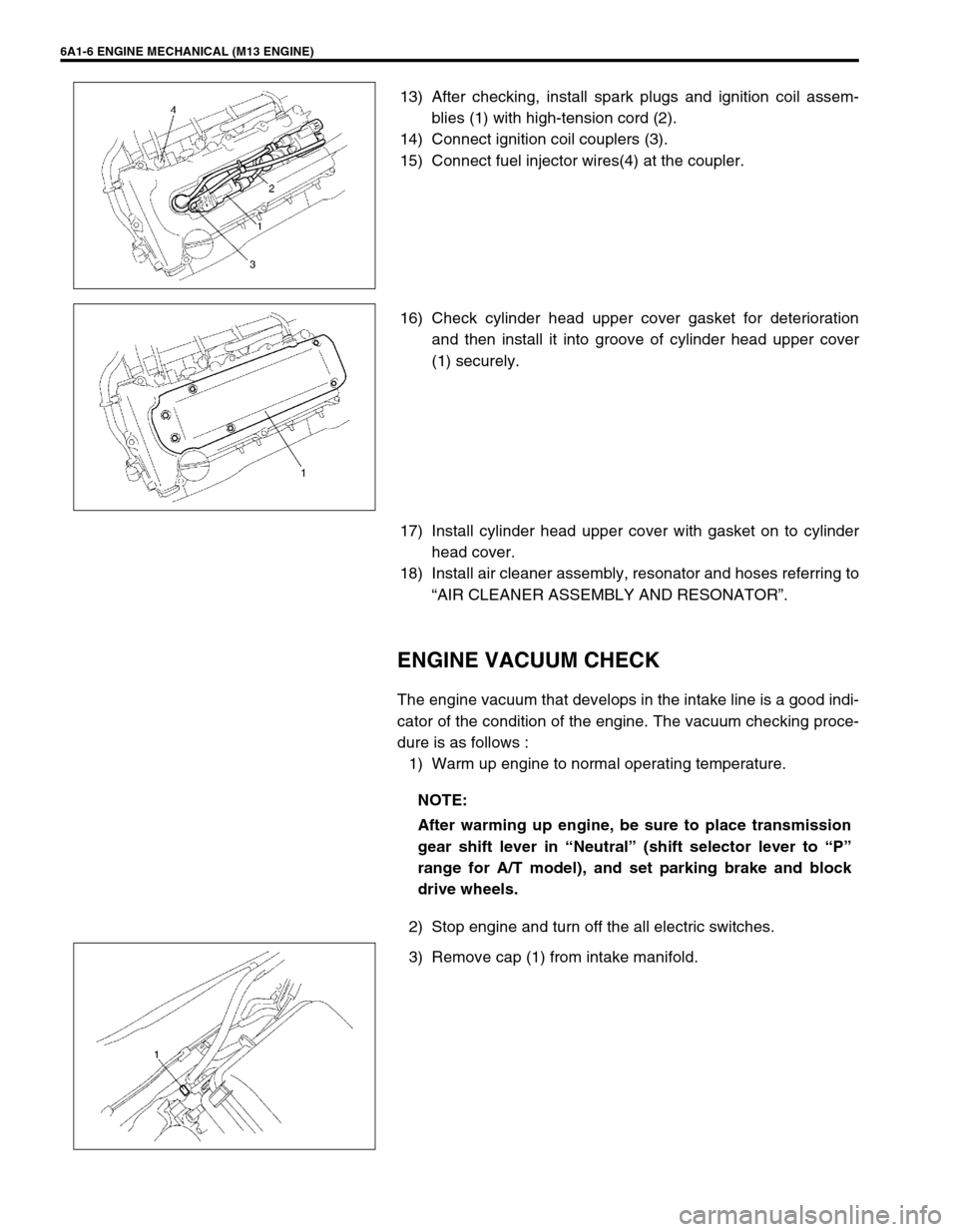
13) After checking, install spark plugs and ignition coil assem-
blies (1) with high-tension cord (2).
14) Connect ignition coil couplers (3).
15) Connect fuel injector wires(4) at the coupler.
16) Check cylinder head upper cover gasket for deterioration
and then install it into groove of cylinder head upper cover
(1) securely.
17) Install cylinder head upper cover with gasket on to cylinder
head cover.
18) Install air cleaner assembly, resonator and hoses referring to
“AIR CLEANER ASSEMBLY AND RESONATOR”.
ENGINE VACUUM CHECK
The engine vacuum that develops in the intake line is a good indi-
cator of the condition of the engine. The vacuum checking proce-
dure is as follows :
1) Warm up engine to normal operating temperature.
2) Stop engine and turn off the all electric switches.
3) Remove cap (1) from intake manifold.
NOTE:
After warming up engine, be sure to place transmission
gear shift lever in “Neutral” (shift selector lever to “P”
range for A/T model), and set parking brake and block
drive wheels.
Page 516 of 698
ENGINE MECHANICAL (M13 ENGINE) 6A1-15
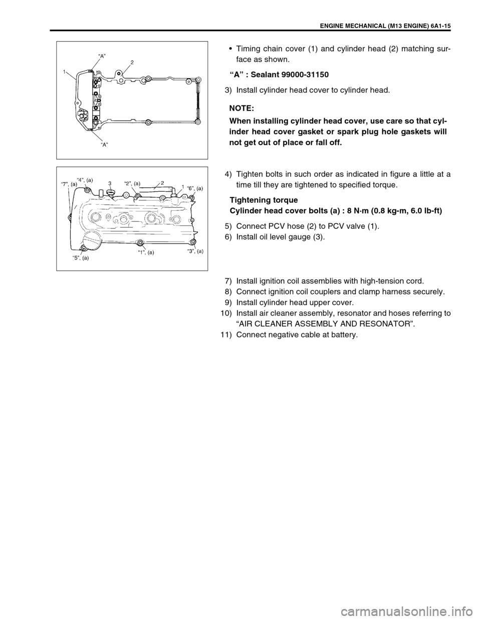
Timing chain cover (1) and cylinder head (2) matching sur-
face as shown.
“A” : Sealant 99000-31150
3) Install cylinder head cover to cylinder head.
4) Tighten bolts in such order as indicated in figure a little at a
time till they are tightened to specified torque.
Tightening torque
Cylinder head cover bolts (a) : 8 N·m (0.8 kg-m, 6.0 lb-ft)
5) Connect PCV hose (2) to PCV valve (1).
6) Install oil level gauge (3).
7) Install ignition coil assemblies with high-tension cord.
8) Connect ignition coil couplers and clamp harness securely.
9) Install cylinder head upper cover.
10) Install air cleaner assembly, resonator and hoses referring to
“AIR CLEANER ASSEMBLY AND RESONATOR”.
11) Connect negative cable at battery.NOTE:
When installing cylinder head cover, use care so that cyl-
inder head cover gasket or spark plug hole gaskets will
not get out of place or fall off.
Page 522 of 698
ENGINE MECHANICAL (M13 ENGINE) 6A1-21
4) Install exhaust manifold cover (1) .
5) Connect heated oxygen sensor coupler (2) and fit coupler to
bracket securely (if equipped).
6) Install heat insulator panel and front bumper with front grille
by referring to Section 9.
7) Connect negative cable at battery.
8) Check exhaust system for exhaust gas leakage.
OIL PAN AND OIL PUMP STRAINER
REMOVAL
1) Disconnect negative cable at battery.
2) Disconnect heated oxygen sensor coupler and detach it from
its stay.
3) Remove oil level gauge.
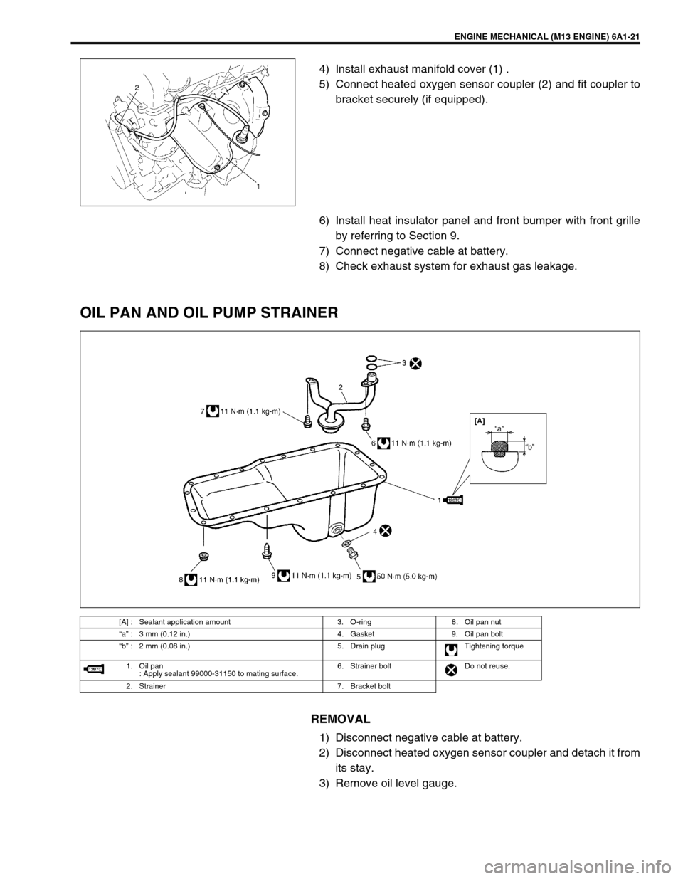
[A] : Sealant application amount 3. O-ring 8. Oil pan nut
“a” : 3 mm (0.12 in.) 4. Gasket 9. Oil pan bolt
“b” : 2 mm (0.08 in.) 5. Drain plug Tightening torque
1. Oil pan
: Apply sealant 99000-31150 to mating surface.6. Strainer bolt Do not reuse.
2. Strainer 7. Bracket bolt
Page 524 of 698
ENGINE MECHANICAL (M13 ENGINE) 6A1-23
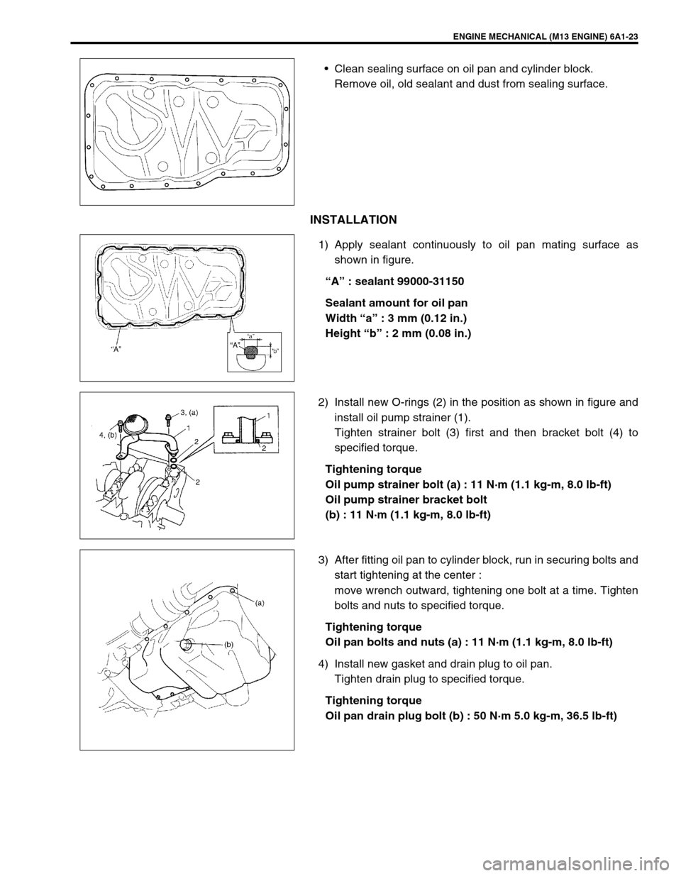
Clean sealing surface on oil pan and cylinder block.
Remove oil, old sealant and dust from sealing surface.
INSTALLATION
1) Apply sealant continuously to oil pan mating surface as
shown in figure.
“A” : sealant 99000-31150
Sealant amount for oil pan
Width “a” : 3 mm (0.12 in.)
Height “b” : 2 mm (0.08 in.)
2) Install new O-rings (2) in the position as shown in figure and
install oil pump strainer (1).
Tighten strainer bolt (3) first and then bracket bolt (4) to
specified torque.
Tightening torque
Oil pump strainer bolt (a) : 11 N·m (1.1 kg-m, 8.0 lb-ft)
Oil pump strainer bracket bolt
(b) : 11 N·m (1.1 kg-m, 8.0 lb-ft)
3) After fitting oil pan to cylinder block, run in securing bolts and
start tightening at the center :
move wrench outward, tightening one bolt at a time. Tighten
bolts and nuts to specified torque.
Tightening torque
Oil pan bolts and nuts (a) : 11 N·m (1.1 kg-m, 8.0 lb-ft)
4) Install new gasket and drain plug to oil pan.
Tighten drain plug to specified torque.
Tightening torque
Oil pan drain plug bolt (b) : 50 N·m 5.0 kg-m, 36.5 lb-ft)
Page 529 of 698
6A1-28 ENGINE MECHANICAL (M13 ENGINE)
INSTALLATION
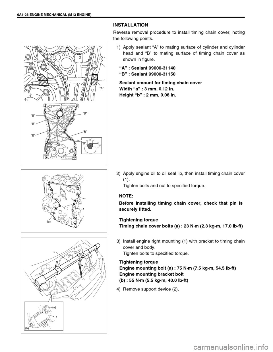
Reverse removal procedure to install timing chain cover, noting
the following points.
1) Apply sealant “A” to mating surface of cylinder and cylinder
head and “B” to mating surface of timing chain cover as
shown in figure.
“A” : Sealant 99000-31140
“B” : Sealant 99000-31150
Sealant amount for timing chain cover
Width “a” : 3 mm, 0.12 in.
Height “b” : 2 mm, 0.08 in.
2) Apply engine oil to oil seal lip, then install timing chain cover
(1).
Tighten bolts and nut to specified torque.
Tightening torque
Timing chain cover bolts (a) : 23 N·m (2.3 kg-m, 17.0 lb-ft)
3) Install engine right mounting (1) with bracket to timing chain
cover and body.
Tighten bolts to specified torque.
Tightening torque
Engine mounting bolt (a) : 75 N·m (7.5 kg-m, 54.5 lb-ft)
Engine mounting bracket bolt
(b) : 55 N·m (5.5 kg-m, 40.0 lb-ft)
4) Remove support device (2).
NOTE:
Before installing timing chain cover, check that pin is
securely fitted.
Page 530 of 698
ENGINE MECHANICAL (M13 ENGINE) 6A1-29
5) Install cylinder head cover referring to “CYLINDER HEAD
COVER”.
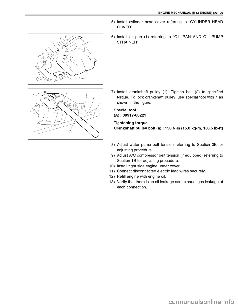
6) Install oil pan (1) referring to “OIL PAN AND OIL PUMP
STRAINER”.
7) Install crankshaft pulley (1). Tighten bolt (2) to specified
torque. To lock crankshaft pulley, use special tool with it as
shown in the figure.
Special tool
(A) : 09917-68221
Tightening torque
Crankshaft pulley bolt (a) : 150 N·m (15.0 kg-m, 108.5 lb-ft)
8) Adjust water pump belt tension referring to Section 0B for
adjusting procedure.
9) Adjust A/C compressor belt tension (if equipped) referring to
Section 1B for adjusting procedure.
10) Install right side engine under cover.
11) Connect disconnected electric lead wires securely.
12) Refill engine with engine oil.
13) Verify that there is no oil leakage and exhaust gas leakage at
each connection.
Page 557 of 698
6A1-56 ENGINE MECHANICAL (M13 ENGINE)
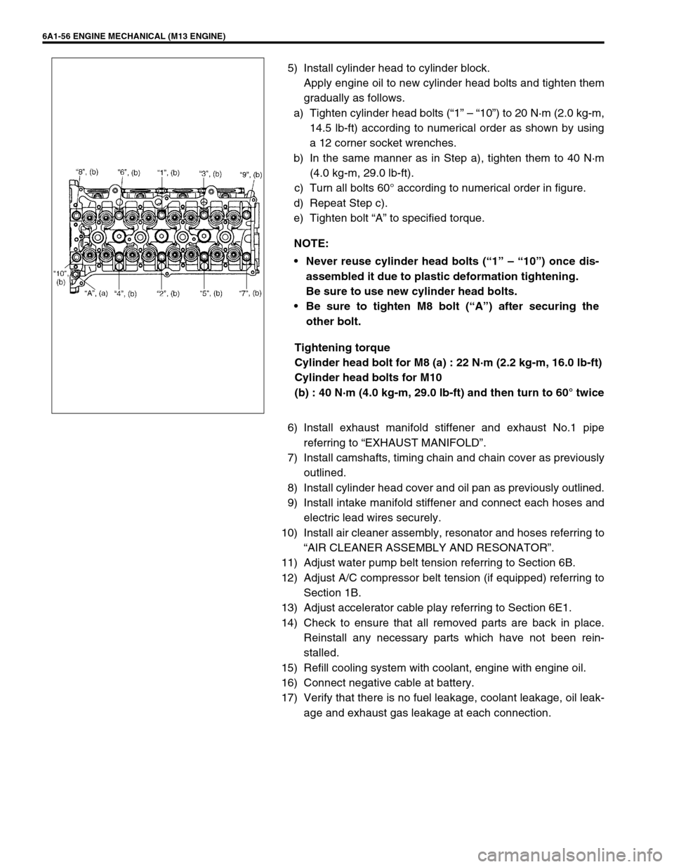
5) Install cylinder head to cylinder block.
Apply engine oil to new cylinder head bolts and tighten them
gradually as follows.
a) Tighten cylinder head bolts (“1” – “10”) to 20 N·m (2.0 kg-m,
14.5 lb-ft) according to numerical order as shown by using
a 12 corner socket wrenches.
b) In the same manner as in Step a), tighten them to 40 N·m
(4.0 kg-m, 29.0 lb-ft).
c) Turn all bolts 60° according to numerical order in figure.
d) Repeat Step c).
e) Tighten bolt “A” to specified torque.
Tightening torque
Cylinder head bolt for M8 (a) : 22 N·m (2.2 kg-m, 16.0 lb-ft)
Cylinder head bolts for M10
(b) : 40 N·m (4.0 kg-m, 29.0 lb-ft) and then turn to 60° twice
6) Install exhaust manifold stiffener and exhaust No.1 pipe
referring to “EXHAUST MANIFOLD”.
7) Install camshafts, timing chain and chain cover as previously
outlined.
8) Install cylinder head cover and oil pan as previously outlined.
9) Install intake manifold stiffener and connect each hoses and
electric lead wires securely.
10) Install air cleaner assembly, resonator and hoses referring to
“AIR CLEANER ASSEMBLY AND RESONATOR”.
11) Adjust water pump belt tension referring to Section 6B.
12) Adjust A/C compressor belt tension (if equipped) referring to
Section 1B.
13) Adjust accelerator cable play referring to Section 6E1.
14) Check to ensure that all removed parts are back in place.
Reinstall any necessary parts which have not been rein-
stalled.
15) Refill cooling system with coolant, engine with engine oil.
16) Connect negative cable at battery.
17) Verify that there is no fuel leakage, coolant leakage, oil leak-
age and exhaust gas leakage at each connection. NOTE:
Never reuse cylinder head bolts (“1” – “10”) once dis-
assembled it due to plastic deformation tightening.
Be sure to use new cylinder head bolts.
Be sure to tighten M8 bolt (“A”) after securing the
other bolt.
Page 600 of 698
ENGINE COOLING 6B-11
COOLING SYSTEM DRAINING
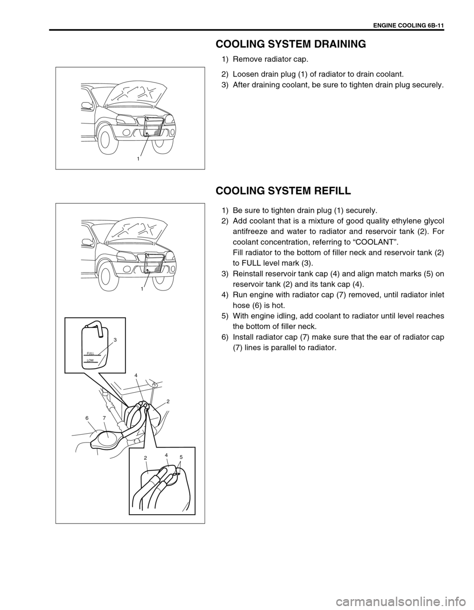
1) Remove radiator cap.
2) Loosen drain plug (1) of radiator to drain coolant.
3) After draining coolant, be sure to tighten drain plug securely.
COOLING SYSTEM REFILL
1) Be sure to tighten drain plug (1) securely.
2) Add coolant that is a mixture of good quality ethylene glycol
antifreeze and water to radiator and reservoir tank (2). For
coolant concentration, referring to “COOLANT”.
Fill radiator to the bottom of filler neck and reservoir tank (2)
to FULL level mark (3).
3) Reinstall reservoir tank cap (4) and align match marks (5) on
reservoir tank (2) and its tank cap (4).
4) Run engine with radiator cap (7) removed, until radiator inlet
hose (6) is hot.
5) With engine idling, add coolant to radiator until level reaches
the bottom of filler neck.
6) Install radiator cap (7) make sure that the ear of radiator cap
(7) lines is parallel to radiator.
1
LOW FULL
5 2
7 6
2 3
4
4
1
Page 601 of 698
6B-12 ENGINE COOLING
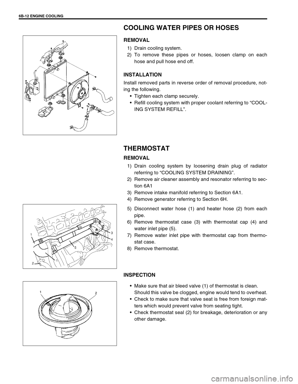
COOLING WATER PIPES OR HOSES
REMOVAL
1) Drain cooling system.
2) To remove these pipes or hoses, loosen clamp on each
hose and pull hose end off.
INSTALLATION
Install removed parts in reverse order of removal procedure, not-
ing the following.
Tighten each clamp securely.
Refill cooling system with proper coolant referring to “COOL-
ING SYSTEM REFILL”.
THERMOSTAT
REMOVAL
1) Drain cooling system by loosening drain plug of radiator
referring to “COOLING SYSTEM DRAINING”.
2) Remove air cleaner assembly and resonator referring to sec-
tion 6A1
3) Remove intake manifold referring to Section 6A1.
4) Remove generator referring to Section 6H.
5) Disconnect water hose (1) and heater hose (2) from each
pipe.
6) Remove thermostat case (3) with thermostat cap (4) and
water inlet pipe (5).
7) Remove water inlet pipe with thermostat cap from thermo-
stat case.
8) Remove thermostat.
INSPECTION
Make sure that air bleed valve (1) of thermostat is clean.
Should this valve be clogged, engine would tend to overheat.
Check to make sure that valve seat is free from foreign mat-
ters which would prevent valve from seating tight.
Check thermostat seal (2) for breakage, deterioration or any
other damage.
Page 610 of 698
ENGINE FUEL 6C-3
PRECAUTIONS
WARNING:
Before attempting service of any type on fuel system, the
followings should be always observed in order to reduce
the risk or fire and personal injury.
Disconnect negative cable at battery.
Do not smoke, and place no smoking signs near work
area.
Be sure to have CO
2 fire extinguisher handy.
Be sure to perform work in a well-ventilated area and
away from any open flames (such as gas hot heater).
Wear safety glasses.
To relieve fuel vapor pressure in fuel tank, remove fuel
filler cap from fuel filler neck and then reinstall it.
As fuel feed line is still under high fuel pressure even
after engine was stopped, loosening or disconnecting
fuel feed line directly may cause dangerous spout of
fuel to occur where loosened or disconnected.
Before loosening or disconnecting fuel feed line, make
sure to relieve fuel pressure “FUEL PRESSURE
RELIEF PROCEDURE” in Section 6.
A small amount of fuel may be released after the fuel
line is disconnected. In order to reduce the chance of
personal injury, cover the fitting to be disconnected
with a shop cloth. Be sure to put that cloth in an
approved container when disconnection is completed.
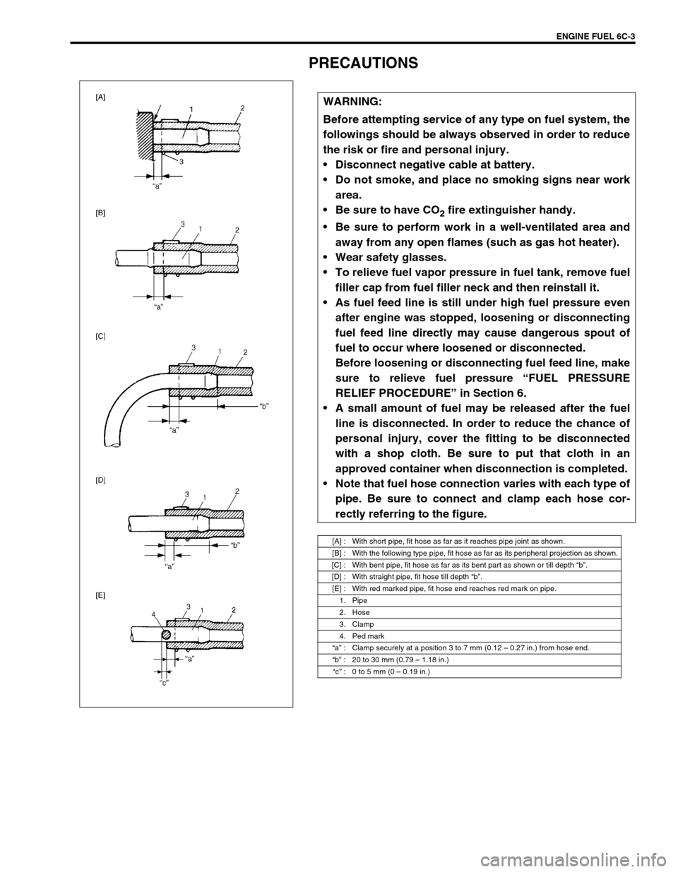
Note that fuel hose connection varies with each type of
pipe. Be sure to connect and clamp each hose cor-
rectly referring to the figure.
[A] : With short pipe, fit hose as far as it reaches pipe joint as shown.
[B] : With the following type pipe, fit hose as far as its peripheral projection as shown.
[C] : With bent pipe, fit hose as far as its bent part as shown or till depth “b”.
[D] : With straight pipe, fit hose till depth “b”.
[E] : With red marked pipe, fit hose end reaches red mark on pipe.
1. Pipe
2. Hose
3. Clamp
4. Ped mark
“a” : Clamp securely at a position 3 to 7 mm (0.12 – 0.27 in.) from hose end.
“b” : 20 to 30 mm (0.79 – 1.18 in.)
“c” : 0 to 5 mm (0 – 0.19 in.)