fuse SUZUKI SWIFT 2000 1.G RG413 Service Owner's Manual
[x] Cancel search | Manufacturer: SUZUKI, Model Year: 2000, Model line: SWIFT, Model: SUZUKI SWIFT 2000 1.GPages: 698, PDF Size: 16.01 MB
Page 338 of 698
ANTILOCK BRAKE SYSTEM (ABS) 5E-13
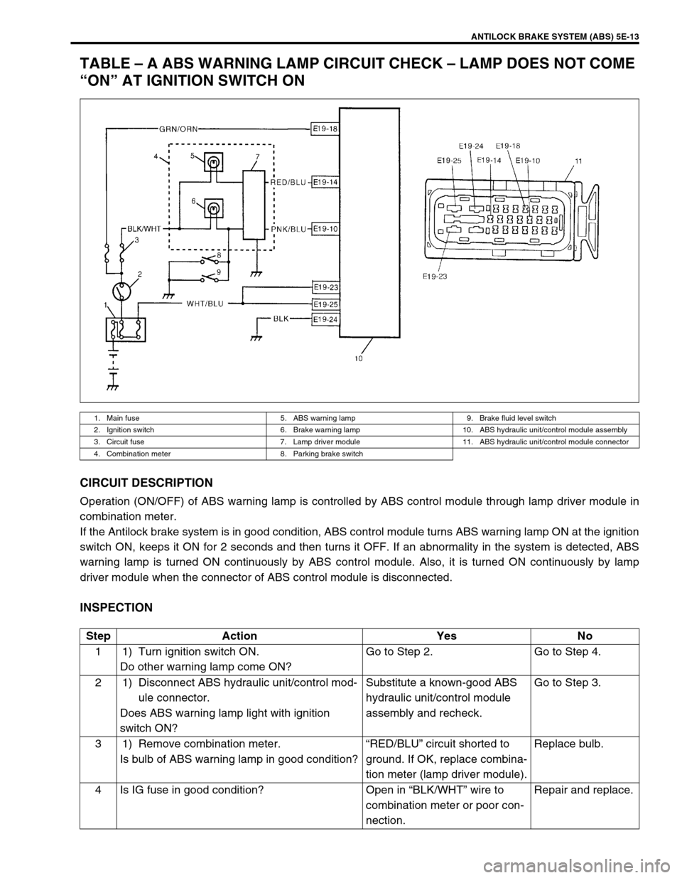
TABLE – A ABS WARNING LAMP CIRCUIT CHECK – LAMP DOES NOT COME
“ON” AT IGNITION SWITCH ON
CIRCUIT DESCRIPTION
Operation (ON/OFF) of ABS warning lamp is controlled by ABS control module through lamp driver module in
combination meter.
If the Antilock brake system is in good condition, ABS control module turns ABS warning lamp ON at the ignition
switch ON, keeps it ON for 2 seconds and then turns it OFF. If an abnormality in the system is detected, ABS
warning lamp is turned ON continuously by ABS control module. Also, it is turned ON continuously by lamp
driver module when the connector of ABS control module is disconnected.
INSPECTION
1. Main fuse 5. ABS warning lamp 9. Brake fluid level switch
2. Ignition switch 6. Brake warning lamp 10. ABS hydraulic unit/control module assembly
3. Circuit fuse 7. Lamp driver module 11. ABS hydraulic unit/control module connector
4. Combination meter 8. Parking brake switch
Step Action Yes No
1 1) Turn ignition switch ON.
Do other warning lamp come ON?Go to Step 2. Go to Step 4.
2 1) Disconnect ABS hydraulic unit/control mod-
ule connector.
Does ABS warning lamp light with ignition
switch ON?Substitute a known-good ABS
hydraulic unit/control module
assembly and recheck.Go to Step 3.
3 1) Remove combination meter.
Is bulb of ABS warning lamp in good condition?“RED/BLU” circuit shorted to
ground. If OK, replace combina-
tion meter (lamp driver module).Replace bulb.
4 Is IG fuse in good condition? Open in “BLK/WHT” wire to
combination meter or poor con-
nection.Repair and replace.
Page 352 of 698

ANTILOCK BRAKE SYSTEM (ABS) 5E-27
DTC C1057 (DTC 57) – POWER SOURCE CIRCUIT
DESCRIPTION
The ABS control module monitors the power source voltage at terminal “E19-18”. When the power source volt-
age becomes extremely high or low, this DTC will be set. As soon as the voltage rises or lowers to the specified
level, the set DTC will be cleared.
INSPECTION
1. Ignition switch 3. ABS hydraulic unit/control module assembly
2. Main fuse 4. ABS hydraulic unit/control module connector
Step Action Yes No
1 1) Connect a voltmeter between battery posi-
tive (+) terminal and body ground.
2) Start the engine and measure the maximum
voltage when racing the engine.
Is it over 18V?Check charging system
referring to “CHARGING
SYSTEM” section.Go to Step 2.
2 1) Disconnect ABS hydraulic unit/control mod-
ule connector.
2) Keep the engine idling, measure the voltage
between terminal “E19-18” of ABS control
module and body ground.
Is it always under 9V?Check charging system
referring to “CHARGING
SYSTEM” section.
Imperfect short between
wire “GRN/ORN” and
ground.Poor connection of termi-
nal “E19-18” or “E19-24”
of the ABS control mod-
ule.
If the above are in good
condition, substitute a
known-good ABS hydrau-
lic unit/control module and
recheck.
Page 354 of 698
ANTILOCK BRAKE SYSTEM (ABS) 5E-29
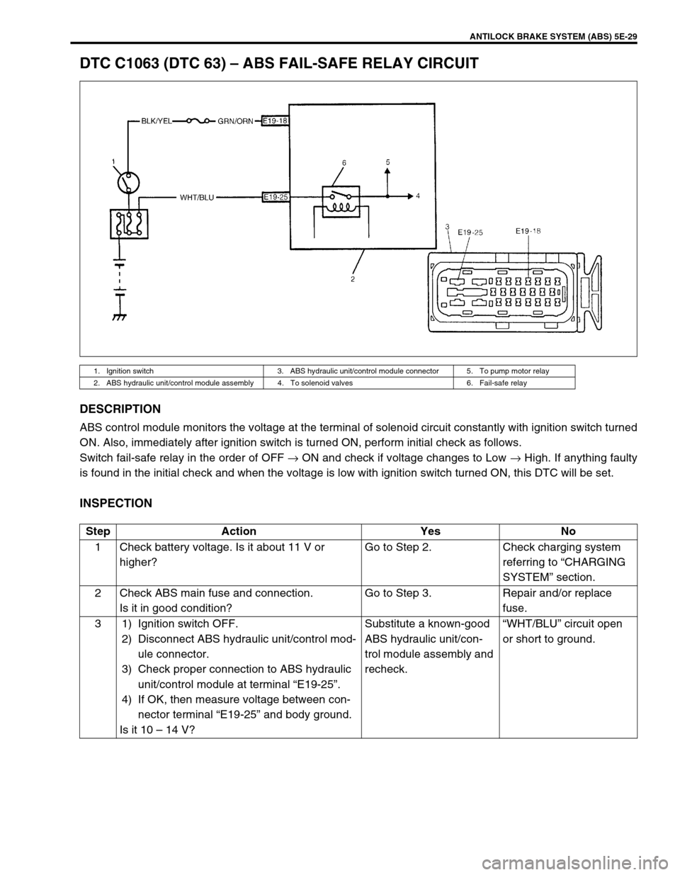
DTC C1063 (DTC 63) – ABS FAIL-SAFE RELAY CIRCUIT
DESCRIPTION
ABS control module monitors the voltage at the terminal of solenoid circuit constantly with ignition switch turned
ON. Also, immediately after ignition switch is turned ON, perform initial check as follows.
Switch fail-safe relay in the order of OFF → ON and check if voltage changes to Low → High. If anything faulty
is found in the initial check and when the voltage is low with ignition switch turned ON, this DTC will be set.
INSPECTION
1. Ignition switch 3. ABS hydraulic unit/control module connector 5. To pump motor relay
2. ABS hydraulic unit/control module assembly 4. To solenoid valves 6. Fail-safe relay
Step Action Yes No
1 Check battery voltage. Is it about 11 V or
higher?Go to Step 2. Check charging system
referring to “CHARGING
SYSTEM” section.
2 Check ABS main fuse and connection.
Is it in good condition?Go to Step 3. Repair and/or replace
fuse.
3 1) Ignition switch OFF.
2) Disconnect ABS hydraulic unit/control mod-
ule connector.
3) Check proper connection to ABS hydraulic
unit/control module at terminal “E19-25”.
4) If OK, then measure voltage between con-
nector terminal “E19-25” and body ground.
Is it 10 – 14 V?Substitute a known-good
ABS hydraulic unit/con-
trol module assembly and
recheck.“WHT/BLU” circuit open
or short to ground.
Page 368 of 698
ANTILOCK BRAKE SYSTEM (ABS) 5E-43
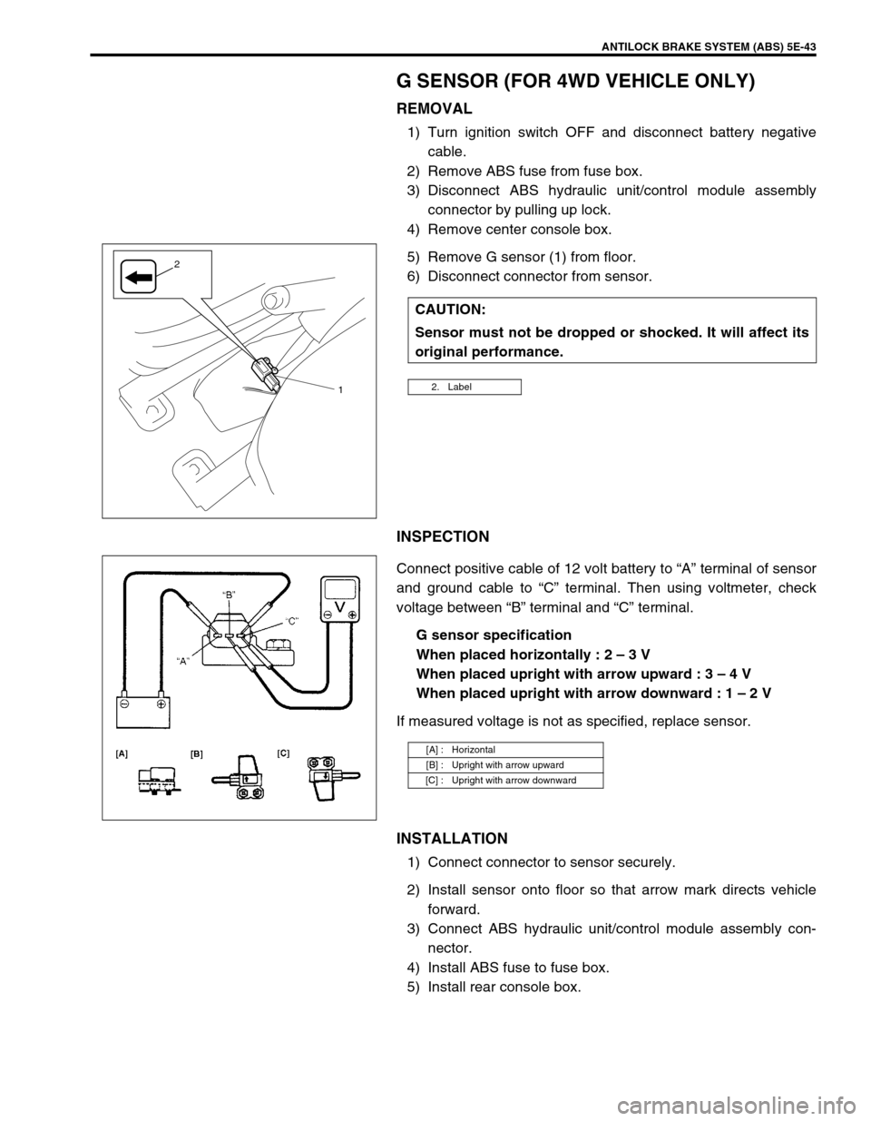
G SENSOR (FOR 4WD VEHICLE ONLY)
REMOVAL
1) Turn ignition switch OFF and disconnect battery negative
cable.
2) Remove ABS fuse from fuse box.
3) Disconnect ABS hydraulic unit/control module assembly
connector by pulling up lock.
4) Remove center console box.
5) Remove G sensor (1) from floor.
6) Disconnect connector from sensor.
INSPECTION
Connect positive cable of 12 volt battery to “A” terminal of sensor
and ground cable to “C” terminal. Then using voltmeter, check
voltage between “B” terminal and “C” terminal.
G sensor specification
When placed horizontally : 2 – 3 V
When placed upright with arrow upward : 3 – 4 V
When placed upright with arrow downward : 1 – 2 V
If measured voltage is not as specified, replace sensor.
INSTALLATION
1) Connect connector to sensor securely.
2) Install sensor onto floor so that arrow mark directs vehicle
forward.
3) Connect ABS hydraulic unit/control module assembly con-
nector.
4) Install ABS fuse to fuse box.
5) Install rear console box.CAUTION:
Sensor must not be dropped or shocked. It will affect its
original performance.
2. Label1
2
[A] : Horizontal
[B] : Upright with arrow upward
[C] : Upright with arrow downward
Page 380 of 698
ENGINE GENERAL INFORMATION AND DIAGNOSIS 6-11
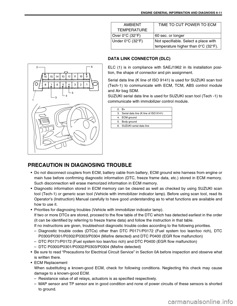
DATA LINK CONNECTOR (DLC)
ELC (1) is in compliance with SAEJ1962 in its installation posi-
tion, the shape of connector and pin assignment.
Serial data line (K line of ISO 9141) is used for SUZUKI scan tool
(Tech-1) to communicate with ECM, TCM, ABS control module
and Air bag SDM.
SUZUKI serial data line is used for SUZUKI scan tool (Tech -1) to
communicate with immobilizer control module.
PRECAUTION IN DIAGNOSING TROUBLE
Do not disconnect couplers from ECM, battery cable from battery, ECM ground wire harness from engine or
main fuse before confirming diagnostic information (DTC, freeze frame data, etc.) stored in ECM memory.
Such disconnection will erase memorized information in ECM memory.
Diagnostic information stored in ECM memory can be cleared as well as checked by using SUZUKI scan
tool (Tech-1) or generic scan tool (Vehicle with immobilizer indicator lamp). Before using scan tool, read its
Operator’s (Instruction) Manual carefully to have good understanding as to what functions are available and
how to use it.
Priorities for diagnosing troubles (Vehicle with immobilizer indicator lamp).
If two or more DTCs are stored, proceed to the flow table of the DTC which has detected earliest in the order
(it can be identified by referring to freeze frame data) and follow the instruction in that table.
If no instructions are given, troubleshoot diagnostic trouble codes according to the following priorities.
–Diagnostic trouble codes (DTCs) other than DTC P0171/P0172 (Fuel system too lean/too rich), DTC
P0300/P0301/P0302/P0303/P0304 (Misfire detected) and DTC P0400 (EGR flow malfunction)
–DTC P0171/P0172 (Fuel system too lean/too rich) and DTC P0400 (EGR flow malfunction)
–DTC P0300/P0301/P0302/P0303/P0304 (Misfire detected)
Be sure to read “Precautions for Electrical Circuit Service” in Section 0A before inspection and observe what
is written there.
ECM Replacement
When substituting a known-good ECM, check for following conditions. Neglecting this check may cause
damage to a known-good ECM.
–Resistance value of all relays, actuators is as specified respectively.
–MAP sensor and TP sensor are in good condition and none of power circuits of these sensors is shorted
to ground.AMBIENT
TEMPERATURETIME TO CUT POWER TO ECM
Over 0°C (32°F) 60 sec. or longer
Under 0°C (32°F) Not specifiable. Select a place with
temperature higher than 0°C (32°F).
2. B+
3. Serial data line (K line of ISO 9141)
4. ECM ground
5. Body ground
6. SUZUKI serial data line
2
3456
1
Page 385 of 698
![SUZUKI SWIFT 2000 1.G RG413 Service Owners Manual 6-16 ENGINE GENERAL INFORMATION AND DIAGNOSIS
[Without Using SUZUKI Scan Tool] (Vehicle without Immo-
bilizer Indicator Lamp)
1) Check malfunction indicator lamp referring to “Malfunction
Indicator SUZUKI SWIFT 2000 1.G RG413 Service Owners Manual 6-16 ENGINE GENERAL INFORMATION AND DIAGNOSIS
[Without Using SUZUKI Scan Tool] (Vehicle without Immo-
bilizer Indicator Lamp)
1) Check malfunction indicator lamp referring to “Malfunction
Indicator](/img/20/7606/w960_7606-384.png)
6-16 ENGINE GENERAL INFORMATION AND DIAGNOSIS
[Without Using SUZUKI Scan Tool] (Vehicle without Immo-
bilizer Indicator Lamp)
1) Check malfunction indicator lamp referring to “Malfunction
Indicator Lamp Check” in this section.
2) With the ignition switch OFF position, disconnect SUZUKI
scan tool if connected and using service wire (4), connect
diagnosis switch terminal (1) to ground terminal (2) in moni-
tor coupler (3).
3) With the ignition switch ON position and leaving engine OFF,
read DTC from flashing pattern of malfunction indicator
lamp. Refer to “Diagnostic Trouble Code Table”.
If lamp remains ON, go to “Diagnostic Flow Table A-4”.
4) After completing the check, turn the ignition switch OFF posi-
tion and disconnect service wire from monitor coupler.
DIAGNOSTIC TROUBLE CODE (DTC) CLEARANCE
Using Scan Tool
1) Connect SUZUKI scan tool (Tech-1) or generic scan tool
(Vehicle with immobilizer indicator lamp) to data link connec-
tor in the same manner as when making this connection for
DTC check.
2) Turn ignition switch ON.
3) Erase DTC and pending DTC according to instructions dis-
played on scan tool. Refer to scan tool operator’s manual for
further details.
4) After completing the clearance, turn ignition switch off and
disconnect scan tool from data link connector. NOTE:
If abnormality or malfunction lies in two or more areas,
malfunction indicator lamp indicates applicable codes
three times each.
And flashing of these codes is repeated as long as
diagnosis terminal is grounded and ignition switch is
held at ON position.
Take a note of diagnostic trouble code indicated first.
2
14
3
NOTE:
DTC and freeze frame data stored in ECM memory are
also cleared in following cases. Be careful not to clear
them before keeping their record.
When power to ECM is cut off (by disconnecting bat-
tery cable, removing fuse or disconnecting ECM con-
nectors)
When the same malfunction (DTC) is not detected
again during 40 engine warm-up cycles. (Vehicle with
immobilizer indicator lamp)
Page 391 of 698
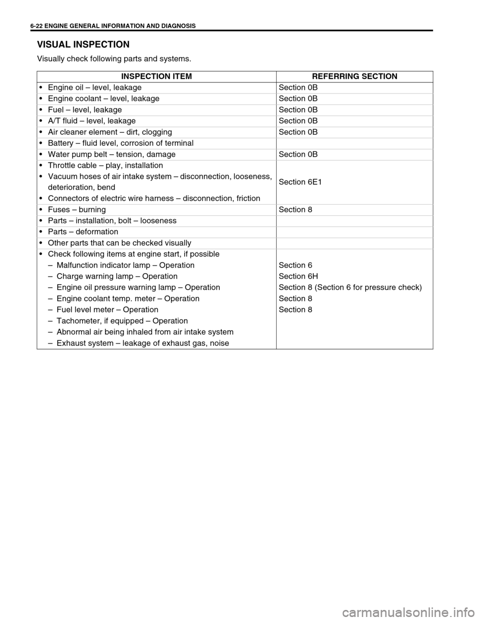
6-22 ENGINE GENERAL INFORMATION AND DIAGNOSIS
VISUAL INSPECTION
Visually check following parts and systems.
INSPECTION ITEM REFERRING SECTION
Engine oil – level, leakage Section 0B
Engine coolant – level, leakage Section 0B
Fuel – level, leakage Section 0B
A/T fluid – level, leakage Section 0B
Air cleaner element – dirt, clogging Section 0B
Battery – fluid level, corrosion of terminal
Water pump belt – tension, damage Section 0B
Throttle cable – play, installation
Section 6E1 Vacuum hoses of air intake system – disconnection, looseness,
deterioration, bend
Connectors of electric wire harness – disconnection, friction
Fuses – burning Section 8
Parts – installation, bolt – looseness
Parts – deformation
Other parts that can be checked visually
Check following items at engine start, if possible
–Malfunction indicator lamp – Operation Section 6
–Charge warning lamp – Operation Section 6H
–Engine oil pressure warning lamp – Operation Section 8 (Section 6 for pressure check)
–Engine coolant temp. meter – Operation Section 8
–Fuel level meter – Operation Section 8
–Tachometer, if equipped – Operation
–Abnormal air being inhaled from air intake system
–Exhaust system – leakage of exhaust gas, noise
Page 415 of 698
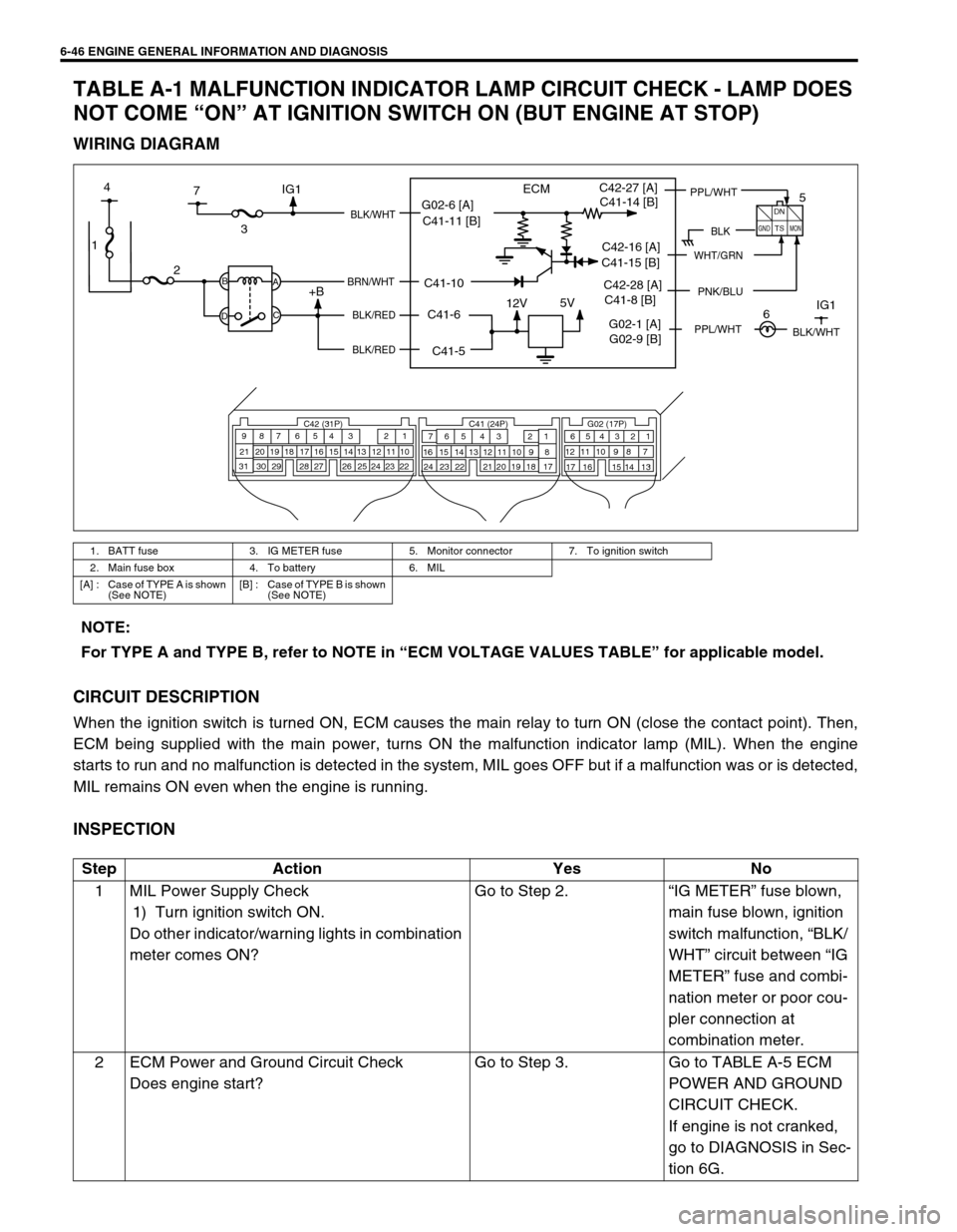
6-46 ENGINE GENERAL INFORMATION AND DIAGNOSIS
TABLE A-1 MALFUNCTION INDICATOR LAMP CIRCUIT CHECK - LAMP DOES
NOT COME “ON” AT IGNITION SWITCH ON (BUT ENGINE AT STOP)
WIRING DIAGRAM
CIRCUIT DESCRIPTION
When the ignition switch is turned ON, ECM causes the main relay to turn ON (close the contact point). Then,
ECM being supplied with the main power, turns ON the malfunction indicator lamp (MIL). When the engine
starts to run and no malfunction is detected in the system, MIL goes OFF but if a malfunction was or is detected,
MIL remains ON even when the engine is running.
INSPECTION
1. BATT fuse 3. IG METER fuse 5. Monitor connector 7. To ignition switch
2. Main fuse box 4. To battery 6. MIL
[A] : Case of TYPE A is shown
(See NOTE)[B] : Case of TYPE B is shown
(See NOTE)
1
12V5V
ECM
23
+BB
DA
C
BLK/WHT
BRN/WHT
BLK/RED
BLK/RED
C42 (31P) C41 (24P) G02 (17P)1 2 3 4 5 6 7 8 9
10 11 12 13 14 15 16 17 18 19 20 21
22 23 24 25 26 28 27 29 30 315 6
1 2 3 4 5 6 7
11 12
9 10 11 13 12 14 15 16
16 171 2
7 8
13 14 3 4
9 10
15 17 188
19 20 21 22 23 24
BLK
DN
TS
GNDMON
PPL/WHTC42-27 [A]
C42-16 [A]
PNK/BLUC42-28 [A]
7 4
G02-1 [A]IG1
5
6IG1
WHT/GRN
BLK/WHT
G02-6 [A]
C41-5 C41-6 C41-10 C41-11 [B]C41-14 [B]
C41-15 [B]
C41-8 [B]
G02-9 [B]
PPL/WHT
NOTE:
For TYPE A and TYPE B, refer to NOTE in “ECM VOLTAGE VALUES TABLE” for applicable model.
Step Action Yes No
1 MIL Power Supply Check
1) Turn ignition switch ON.
Do other indicator/warning lights in combination
meter comes ON?Go to Step 2.“IG METER” fuse blown,
main fuse blown, ignition
switch malfunction, “BLK/
WHT” circuit between “IG
METER” fuse and combi-
nation meter or poor cou-
pler connection at
combination meter.
2 ECM Power and Ground Circuit Check
Does engine start?Go to Step 3. Go to TABLE A-5 ECM
POWER AND GROUND
CIRCUIT CHECK.
If engine is not cranked,
go to DIAGNOSIS in Sec-
tion 6G.
Page 418 of 698
ENGINE GENERAL INFORMATION AND DIAGNOSIS 6-49
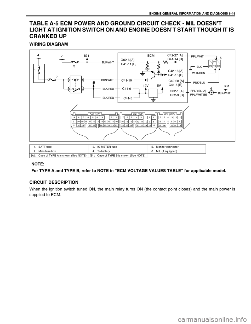
TABLE A-5 ECM POWER AND GROUND CIRCUIT CHECK - MIL DOESN’T
LIGHT AT IGNITION SWITCH ON AND ENGINE DOESN’T START THOUGH IT IS
CRANKED UP
WIRING DIAGRAM
CIRCUIT DESCRIPTION
When the ignition switch tuned ON, the main relay turns ON (the contact point closes) and the main power is
supplied to ECM.
1. BATT fuse 3. IG METER fuse 5. Monitor connector
2. Main fuse box 4. To battery 6. MIL (if equipped)
[A] : Case of TYPE A is shown (See NOTE) [B] : Case of TYPE B is shown (See NOTE)
1
12V5V
ECM
23
+BB
DA
C
BLK/WHT
BRN/WHT
BLK/RED
BLK/RED
C42 (31P) C41 (24P) G02 (17P)1 2 3 4 5 6 7 8 9
10 11 12 13 14 15 16 17 18 19 20 21
22 23 24 25 26 28 27 29 30 315 6
1 2 3 4 5 6 7
11 12
9 10 11 13 12 14 15 16
16 171 2
7 8
13 14 3 4
9 10
15 17 188
19 20 21 22 23 24
BLK
DN
TS
GNDMON
PPL/WHTC42-27 [A]
C42-16 [A]
PNK/BLUC42-28 [A]
7 4
G02-1 [A]IG1PPL/YEL [A]
5
6IG1
WHT/GRN
BLK/WHT
G02-6 [A]
C41-5 C41-6 C41-10 C41-11 [B]C41-14 [B]
C41-15 [B]
C41-8 [B]
G02-9 [B]PPL/WHT [B]
NOTE:
For TYPE A and TYPE B, refer to NOTE in “ECM VOLTAGE VALUES TABLE” for applicable model.
Page 419 of 698
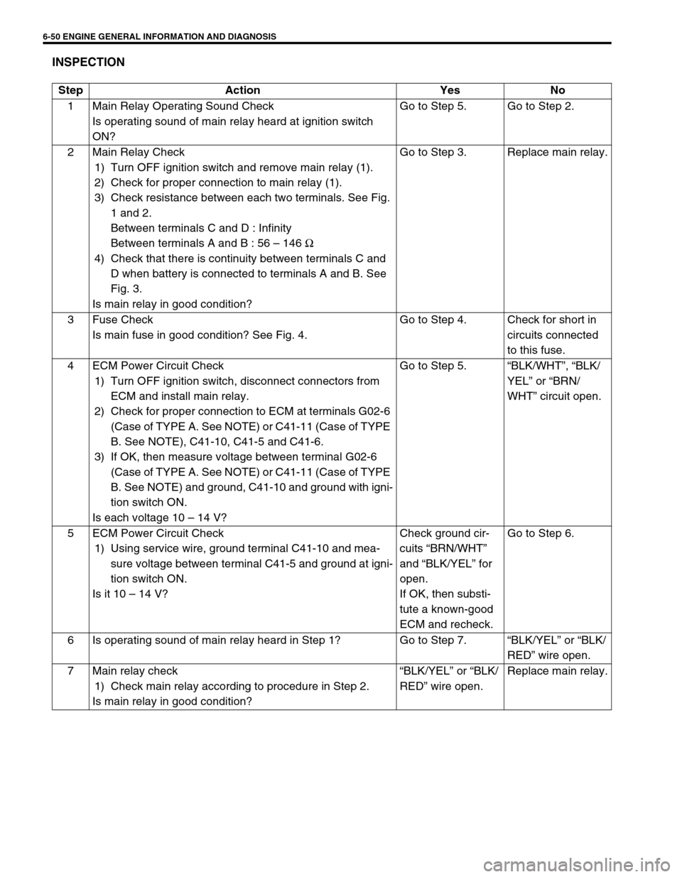
6-50 ENGINE GENERAL INFORMATION AND DIAGNOSIS
INSPECTION
Step Action Yes No
1 Main Relay Operating Sound Check
Is operating sound of main relay heard at ignition switch
ON?Go to Step 5. Go to Step 2.
2 Main Relay Check
1) Turn OFF ignition switch and remove main relay (1).
2) Check for proper connection to main relay (1).
3) Check resistance between each two terminals. See Fig.
1 and 2.
Between terminals C and D : Infinity
Between terminals A and B : 56 – 146 Ω
4) Check that there is continuity between terminals C and
D when battery is connected to terminals A and B. See
Fig. 3.
Is main relay in good condition?Go to Step 3. Replace main relay.
3 Fuse Check
Is main fuse in good condition? See Fig. 4.Go to Step 4. Check for short in
circuits connected
to this fuse.
4 ECM Power Circuit Check
1) Turn OFF ignition switch, disconnect connectors from
ECM and install main relay.
2) Check for proper connection to ECM at terminals G02-6
(Case of TYPE A. See NOTE) or C41-11 (Case of TYPE
B. See NOTE), C41-10, C41-5 and C41-6.
3) If OK, then measure voltage between terminal G02-6
(Case of TYPE A. See NOTE) or C41-11 (Case of TYPE
B. See NOTE) and ground, C41-10 and ground with igni-
tion switch ON.
Is each voltage 10 – 14 V?Go to Step 5.“BLK/WHT”, “BLK/
YEL” or “BRN/
WHT” circuit open.
5 ECM Power Circuit Check
1) Using service wire, ground terminal C41-10 and mea-
sure voltage between terminal C41-5 and ground at igni-
tion switch ON.
Is it 10 – 14 V?Check ground cir-
cuits “BRN/WHT”
and “BLK/YEL” for
open.
If OK, then substi-
tute a known-good
ECM and recheck.Go to Step 6.
6 Is operating sound of main relay heard in Step 1? Go to Step 7.“BLK/YEL” or “BLK/
RED” wire open.
7 Main relay check
1) Check main relay according to procedure in Step 2.
Is main relay in good condition?“BLK/YEL” or “BLK/
RED” wire open.Replace main relay.