parking brake SUZUKI SWIFT 2000 1.G RG413 Service Owner's Manual
[x] Cancel search | Manufacturer: SUZUKI, Model Year: 2000, Model line: SWIFT, Model: SUZUKI SWIFT 2000 1.GPages: 698, PDF Size: 16.01 MB
Page 298 of 698

BRAKES 5-25
REAR BRAKE
1. Brake back plate
: Apply water tight sealant (99000-31090) to joint seam of brake back plate and rear axle 9. Bleeder plug
2. Brake shoe10. Bleeder plug cap
3. Push nut 11. Parking lever spring
4. Shoe hold down spring12. Parking brake shoe lever
5. Shoe return upper spring 13. Brake Drum
6. Shoe hold down pin 14. Spindle nut (For 2WD vehicle only)
: Calk spindle nut after tightening
7. Brake strutTightening torque
8. Wheel cylinder
: Apply brake fluid to piston cup Do not reuse.
Page 299 of 698
5-26 BRAKES
BRAKE DRUM
REMOVAL
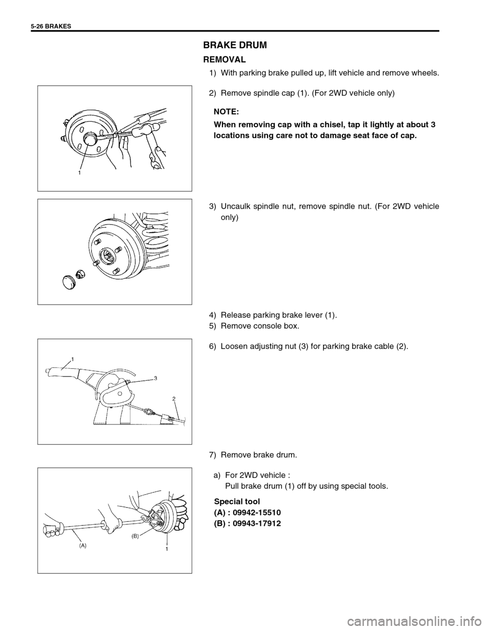
1) With parking brake pulled up, lift vehicle and remove wheels.
2) Remove spindle cap (1). (For 2WD vehicle only)
3) Uncaulk spindle nut, remove spindle nut. (For 2WD vehicle
only)
4) Release parking brake lever (1).
5) Remove console box.
6) Loosen adjusting nut (3) for parking brake cable (2).
7) Remove brake drum.
a) For 2WD vehicle :
Pull brake drum (1) off by using special tools.
Special tool
(A) : 09942-15510
(B) : 09943-17912 NOTE:
When removing cap with a chisel, tap it lightly at about 3
locations using care not to damage seat face of cap.
Page 301 of 698
5-28 BRAKES
INSTALLATION
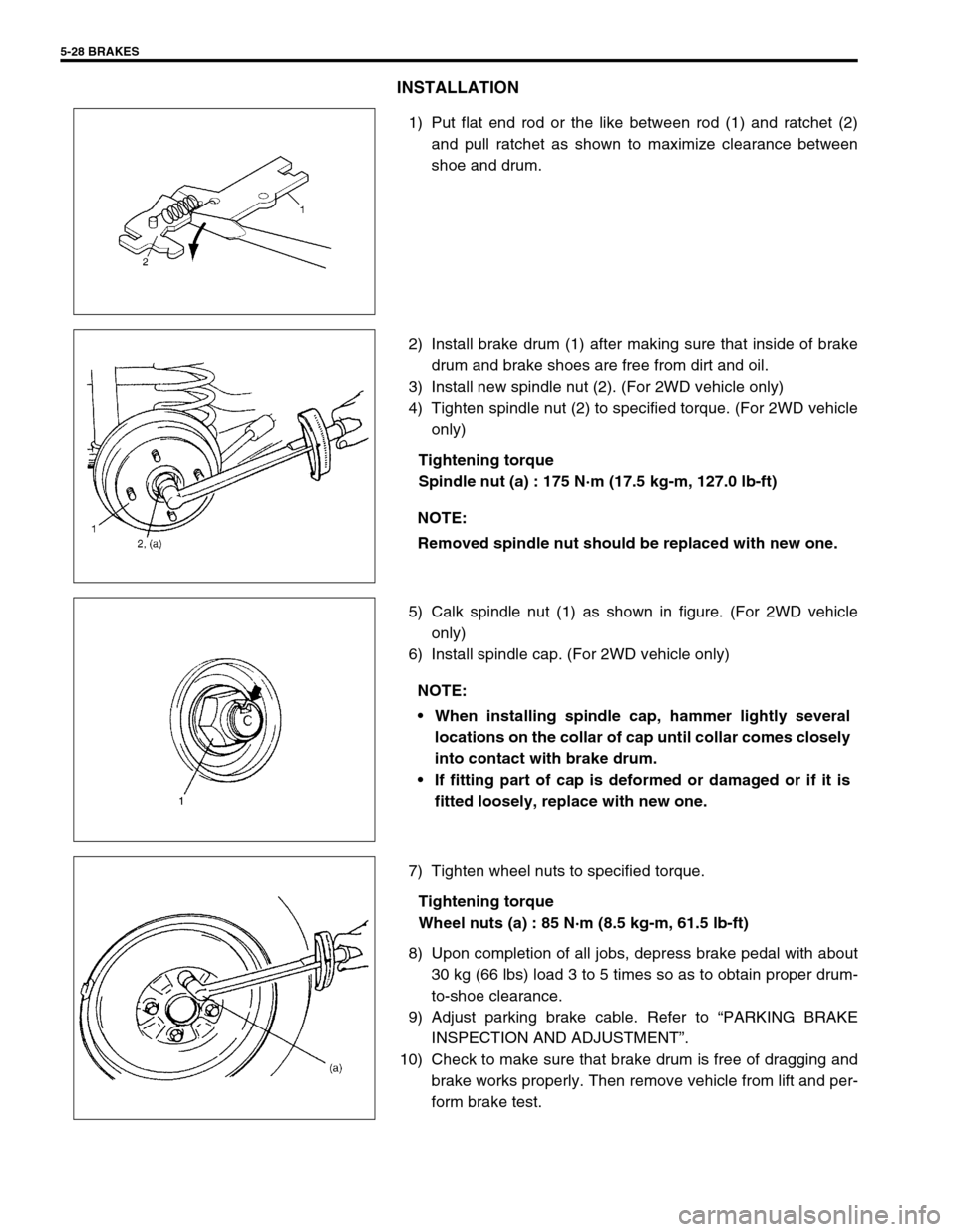
1) Put flat end rod or the like between rod (1) and ratchet (2)
and pull ratchet as shown to maximize clearance between
shoe and drum.
2) Install brake drum (1) after making sure that inside of brake
drum and brake shoes are free from dirt and oil.
3) Install new spindle nut (2). (For 2WD vehicle only)
4) Tighten spindle nut (2) to specified torque. (For 2WD vehicle
only)
Tightening torque
Spindle nut (a) : 175 N·m (17.5 kg-m, 127.0 lb-ft)
5) Calk spindle nut (1) as shown in figure. (For 2WD vehicle
only)
6) Install spindle cap. (For 2WD vehicle only)
7) Tighten wheel nuts to specified torque.
Tightening torque
Wheel nuts (a) : 85 N·m (8.5 kg-m, 61.5 lb-ft)
8) Upon completion of all jobs, depress brake pedal with about
30 kg (66 lbs) load 3 to 5 times so as to obtain proper drum-
to-shoe clearance.
9) Adjust parking brake cable. Refer to “PARKING BRAKE
INSPECTION AND ADJUSTMENT”.
10) Check to make sure that brake drum is free of dragging and
brake works properly. Then remove vehicle from lift and per-
form brake test.
NOTE:
Removed spindle nut should be replaced with new one.
NOTE:
When installing spindle cap, hammer lightly several
locations on the collar of cap until collar comes closely
into contact with brake drum.
If fitting part of cap is deformed or damaged or if it is
fitted loosely, replace with new one.
Page 302 of 698

BRAKES 5-29
BRAKE SHOE
REMOVAL
1) Remove brake drum referring to “BRAKE DRUM”.
2) Remove shoe hold down springs (1) by turning shoe hold
down pins (2).
3) Remove return springs, brake shoes and strut.
4) Disconnect parking brake shoe lever (1) from parking brake
cable (2).
5) Remove push nut (1).
6) Remove parking brake shoe lever (2) from shoe rim (3).
INSPECTION
Check ratchet of brake strut (1) assembly for wear or dam-
age.
Check shoe return spring, strut shoe return spring and shoe
hold down spring for damage, corrosion and weakening.
Check for smooth movement of brake shoe lever (2) along
shoe rim.
CAUTION:
Use a new push nut.
Page 304 of 698
BRAKES 5-31
INSTALLATION
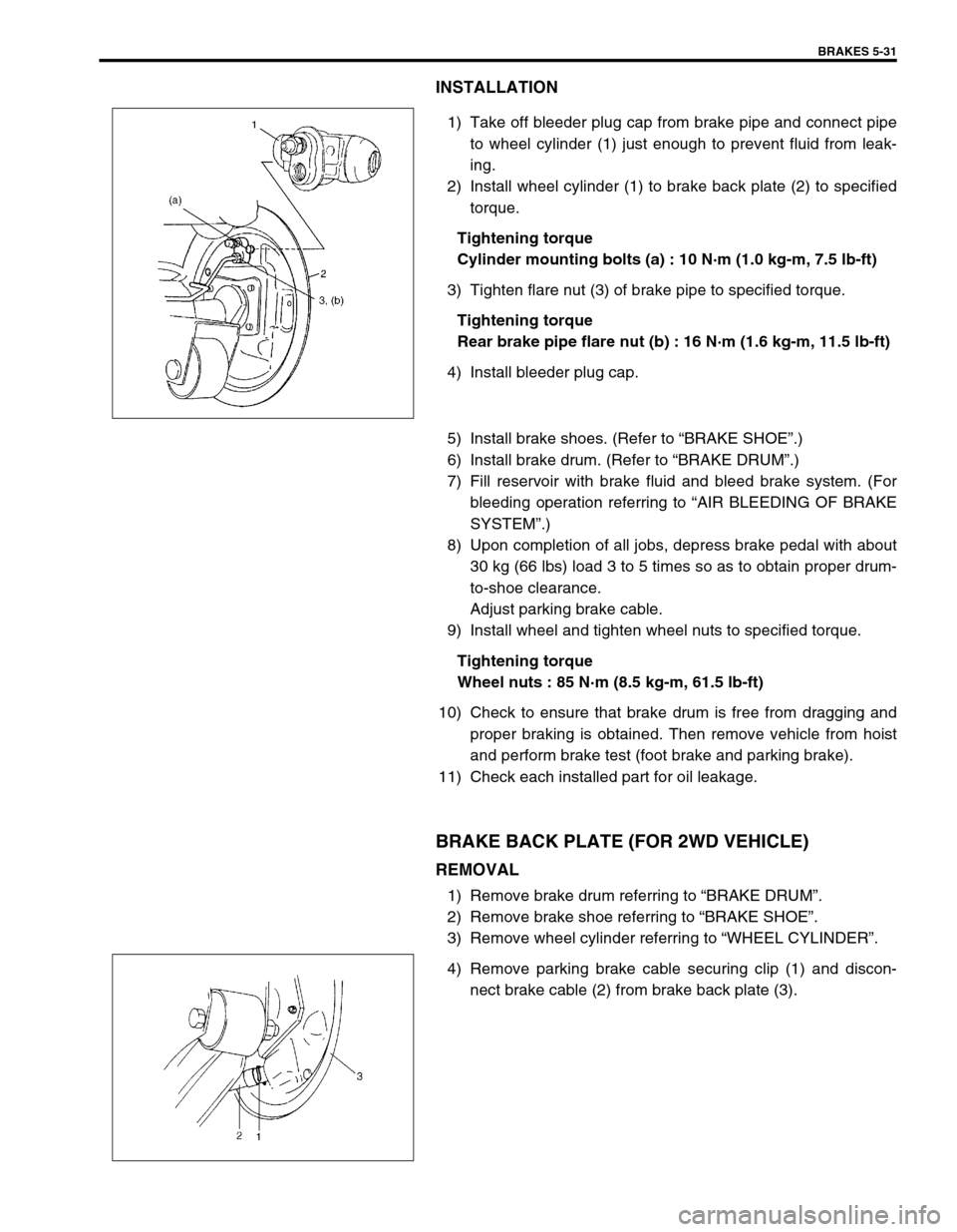
1) Take off bleeder plug cap from brake pipe and connect pipe
to wheel cylinder (1) just enough to prevent fluid from leak-
ing.
2) Install wheel cylinder (1) to brake back plate (2) to specified
torque.
Tightening torque
Cylinder mounting bolts (a) : 10 N·m (1.0 kg-m, 7.5 lb-ft)
3) Tighten flare nut (3) of brake pipe to specified torque.
Tightening torque
Rear brake pipe flare nut (b) : 16 N·m (1.6 kg-m, 11.5 lb-ft)
4) Install bleeder plug cap.
5) Install brake shoes. (Refer to “BRAKE SHOE”.)
6) Install brake drum. (Refer to “BRAKE DRUM”.)
7) Fill reservoir with brake fluid and bleed brake system. (For
bleeding operation referring to “AIR BLEEDING OF BRAKE
SYSTEM”.)
8) Upon completion of all jobs, depress brake pedal with about
30 kg (66 lbs) load 3 to 5 times so as to obtain proper drum-
to-shoe clearance.
Adjust parking brake cable.
9) Install wheel and tighten wheel nuts to specified torque.
Tightening torque
Wheel nuts : 85 N·m (8.5 kg-m, 61.5 lb-ft)
10) Check to ensure that brake drum is free from dragging and
proper braking is obtained. Then remove vehicle from hoist
and perform brake test (foot brake and parking brake).
11) Check each installed part for oil leakage.
BRAKE BACK PLATE (FOR 2WD VEHICLE)
REMOVAL
1) Remove brake drum referring to “BRAKE DRUM”.
2) Remove brake shoe referring to “BRAKE SHOE”.
3) Remove wheel cylinder referring to “WHEEL CYLINDER”.
4) Remove parking brake cable securing clip (1) and discon-
nect brake cable (2) from brake back plate (3).
Page 305 of 698
5-32 BRAKES
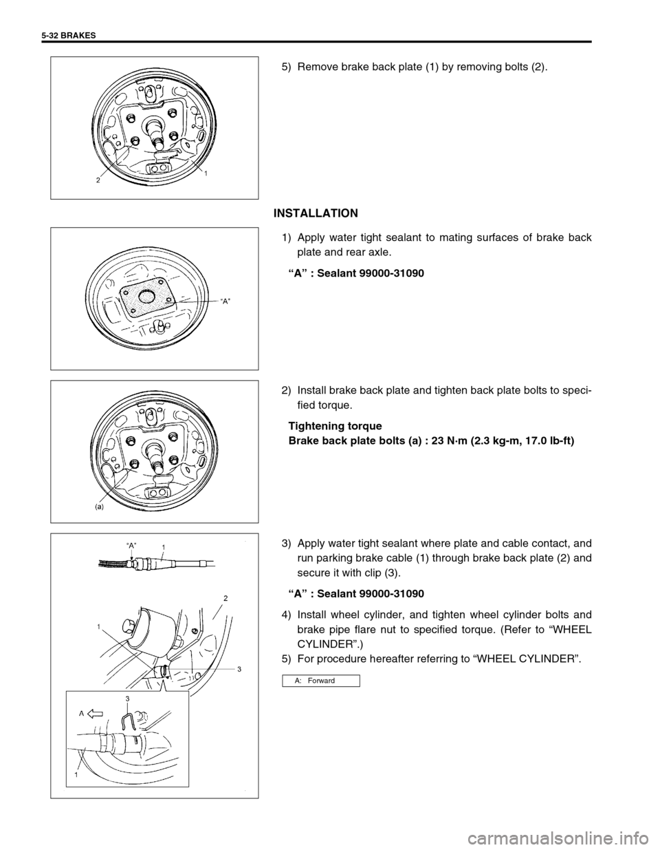
5) Remove brake back plate (1) by removing bolts (2).
INSTALLATION
1) Apply water tight sealant to mating surfaces of brake back
plate and rear axle.
“A” : Sealant 99000-31090
2) Install brake back plate and tighten back plate bolts to speci-
fied torque.
Tightening torque
Brake back plate bolts (a) : 23 N·m (2.3 kg-m, 17.0 lb-ft)
3) Apply water tight sealant where plate and cable contact, and
run parking brake cable (1) through brake back plate (2) and
secure it with clip (3).
“A” : Sealant 99000-31090
4) Install wheel cylinder, and tighten wheel cylinder bolts and
brake pipe flare nut to specified torque. (Refer to “WHEEL
CYLINDER”.)
5) For procedure hereafter referring to “WHEEL CYLINDER”.
A: Forward
Page 319 of 698
5-46 BRAKES
PARKING BRAKE CABLE
REMOVAL
1) Raise, suitably support vehicle and remove wheel.
2) Remove parking brake cable.
INSTALLATION
Install it by reversing removal procedure, noting the following points.
Install clamps properly referring to figure below.
Tighten bolts and nuts to specified torque.
Adjust parking brake cable. (Refer to “PARKING BRAKE INSPECTION AND ADJUSTMENT”.)
Check brake drum for dragging and brake system for proper performance. After removing vehicle from hoist,
brake test should be performed.
Page 320 of 698

BRAKES 5-47
T : Top side 3. Inner cable end a : View A f : View F
F : Front side 4. Spring b : View B Tightening torque
R : Rear side 5. Adjusting nut c : View C
1. Cable
: Apply water tight sealant (99000-31090)6. Clip d : View D
2. Parking brake shoe lever 7. Parking brake lever e : View E
Page 323 of 698

5-50 BRAKES
REQUIRED SERVICE MATERIAL
SPECIAL TOOL
MaterialRecommended SUZUKI product
(Part Number)Use
Brake fluid DOT 3 or SAE J1703To fill master cylinder reservoir.
To clean and apply to inner parts of master
cylinder caliper and wheel cylinder when they
are disassembled.
Water tight sealant SEALING COMPOUND 366E
(99000-31090)To apply to mating surfaces of brake back
plate and rear axle (2WD vehicle) or rear
axle housing (4WD vehicle).
To apply to mating surfaces of brake back
plate and parking brake cable.
Lithium grease SUZUKI SUPER GREASE A
(99000-25010)To apply to slide pin of brake caliper carrier.
09900-06106 09900-20606 09900-20701 09942-15510
Snap ring remover Dial gauge Dial gauge chuck Sliding hammer
09943-17912 09951-18220 09952-16020 09952-46010
Brake drum remover
(Front wheel hub
remover)Secondary cup installer
setBooster piston rod
adjusterMaster cylinder attach-
ment
Page 333 of 698
5E-8 ANTILOCK BRAKE SYSTEM (ABS)
DIAGNOSIS
To ensure that the trouble diagnosis is done accurately and
smoothly, observe “PRECAUTIONS IN DIAGNOSING TROU-
BLES” and follow “ABS DIAGNOSTIC FLOW TABLE”.
PRECAUTION IN DIAGNOSING TROUBLES
If the vehicles was operated in any of the following ways,
ABS warning lamp may light momentarily but this does not
indicate anything abnormal in ABS.
–The vehicle was driven with parking brake pulled.
–The vehicle was driven with brake dragging.
–The vehicle was stuck in mud, sand, etc.
–Wheel spin occurred while driving.
–Wheel(s) was rotated while the vehicle was jacked up.
Be sure to read “PRECAUTIONS FOR ELECTRONIC CIR-
CUIT SERVICE” in Section 0A before inspection and
observe what is written there.
Be sure to use the trouble diagnosis procedure as described
in the flow table. Failure to follow the flow table may result in
incorrect diagnosis. (Some other diagnosis trouble code may
be stored by mistake in the memory of ABS control module
during inspection.)
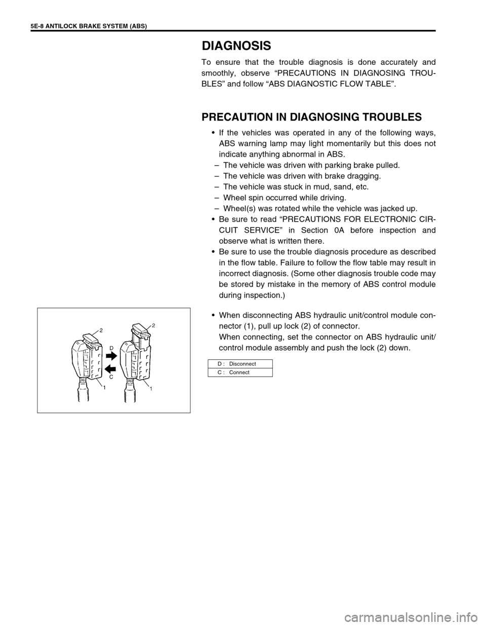
When disconnecting ABS hydraulic unit/control module con-
nector (1), pull up lock (2) of connector.
When connecting, set the connector on ABS hydraulic unit/
control module assembly and push the lock (2) down.
D : Disconnect
C : Connect