parking brake SUZUKI SWIFT 2000 1.G RG413 Service Owner's Guide
[x] Cancel search | Manufacturer: SUZUKI, Model Year: 2000, Model line: SWIFT, Model: SUZUKI SWIFT 2000 1.GPages: 698, PDF Size: 16.01 MB
Page 337 of 698
5E-12 ANTILOCK BRAKE SYSTEM (ABS)
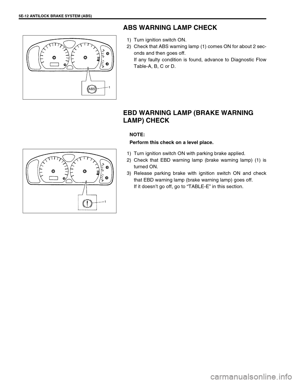
ABS WARNING LAMP CHECK
1) Turn ignition switch ON.
2) Check that ABS warning lamp (1) comes ON for about 2 sec-
onds and then goes off.
If any faulty condition is found, advance to Diagnostic Flow
Table-A, B, C or D.
EBD WARNING LAMP (BRAKE WARNING
LAMP) CHECK
1) Turn ignition switch ON with parking brake applied.
2) Check that EBD warning lamp (brake warning lamp) (1) is
turned ON.
3) Release parking brake with ignition switch ON and check
that EBD warning lamp (brake warning lamp) goes off.
If it doesn’t go off, go to “TABLE-E” in this section.
NOTE:
Perform this check on a level place.
Page 338 of 698
ANTILOCK BRAKE SYSTEM (ABS) 5E-13
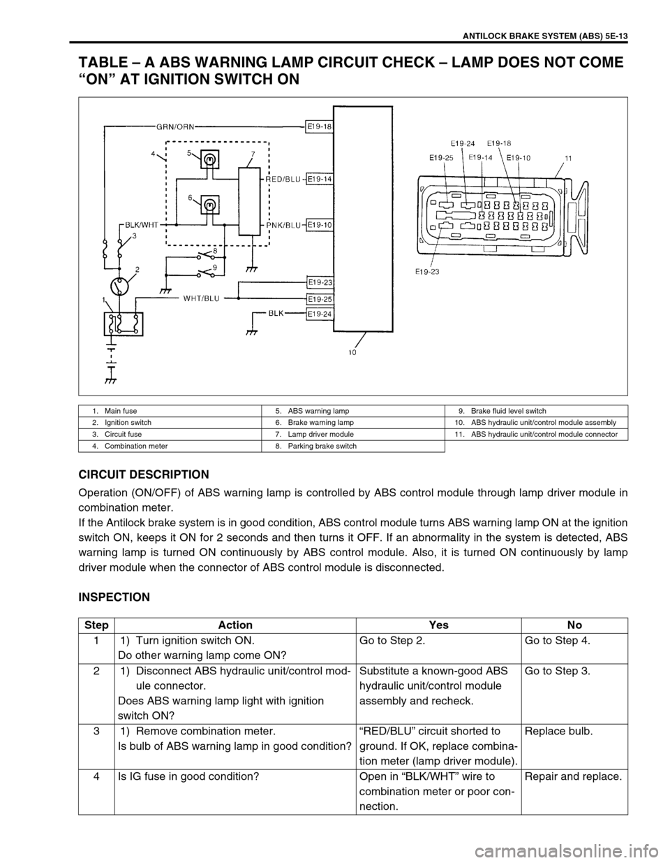
TABLE – A ABS WARNING LAMP CIRCUIT CHECK – LAMP DOES NOT COME
“ON” AT IGNITION SWITCH ON
CIRCUIT DESCRIPTION
Operation (ON/OFF) of ABS warning lamp is controlled by ABS control module through lamp driver module in
combination meter.
If the Antilock brake system is in good condition, ABS control module turns ABS warning lamp ON at the ignition
switch ON, keeps it ON for 2 seconds and then turns it OFF. If an abnormality in the system is detected, ABS
warning lamp is turned ON continuously by ABS control module. Also, it is turned ON continuously by lamp
driver module when the connector of ABS control module is disconnected.
INSPECTION
1. Main fuse 5. ABS warning lamp 9. Brake fluid level switch
2. Ignition switch 6. Brake warning lamp 10. ABS hydraulic unit/control module assembly
3. Circuit fuse 7. Lamp driver module 11. ABS hydraulic unit/control module connector
4. Combination meter 8. Parking brake switch
Step Action Yes No
1 1) Turn ignition switch ON.
Do other warning lamp come ON?Go to Step 2. Go to Step 4.
2 1) Disconnect ABS hydraulic unit/control mod-
ule connector.
Does ABS warning lamp light with ignition
switch ON?Substitute a known-good ABS
hydraulic unit/control module
assembly and recheck.Go to Step 3.
3 1) Remove combination meter.
Is bulb of ABS warning lamp in good condition?“RED/BLU” circuit shorted to
ground. If OK, replace combina-
tion meter (lamp driver module).Replace bulb.
4 Is IG fuse in good condition? Open in “BLK/WHT” wire to
combination meter or poor con-
nection.Repair and replace.
Page 342 of 698
ANTILOCK BRAKE SYSTEM (ABS) 5E-17
TABLE – E EBD WARNING LAMP (BRAKE WARNING LAMP) CHECK – LAMP
COMES “ON” STEADY
CIRCUIT DESCRIPTION
EBD warning lamp (brake warning lamp) is controlled by parking brake switch, brake fluid level switch and ABS
control module/hydraulic unit assembly through lamp driver module in combination meter. Refer to “TABLE – A”
for circuit diagram.
INSPECTION
Step Action Yes No
1 1) Make sure that :
Parking brake is completely released.
Brake fluid level is upper than the minimum
level.
Are the check results OK?Go to Step 2. Release parking brake
completely and/or replen-
ish brake fluid.
2Does “ABS” warning lamp come on? Perform “TABLE – B” pre-
viously outlined.Go to Step 3.
3 1) Disconnect ABS hydraulic unit/control mod-
ule connector.
2) Check for proper connection to ABS
hydraulic unit/control module connector at
terminals “E19-10”.
3) If OK, apply chocks to wheels and select
gear in neutral position (P range for A/T).
4) Keep brake pedal depressed and start
engine.
Release parking brake.
5) Connect terminal “E19-10” of disconnected
connector to ground using service wire.
Does EBD warning lamp (brake warning lamp)
turn off?Substitute a known-good
ABS hydraulic unit/con-
trol module assembly and
recheck.“PNK/BLU” circuit open.
If wire and connection are
OK, replace combination
meter.
Page 349 of 698
5E-24 ANTILOCK BRAKE SYSTEM (ABS)
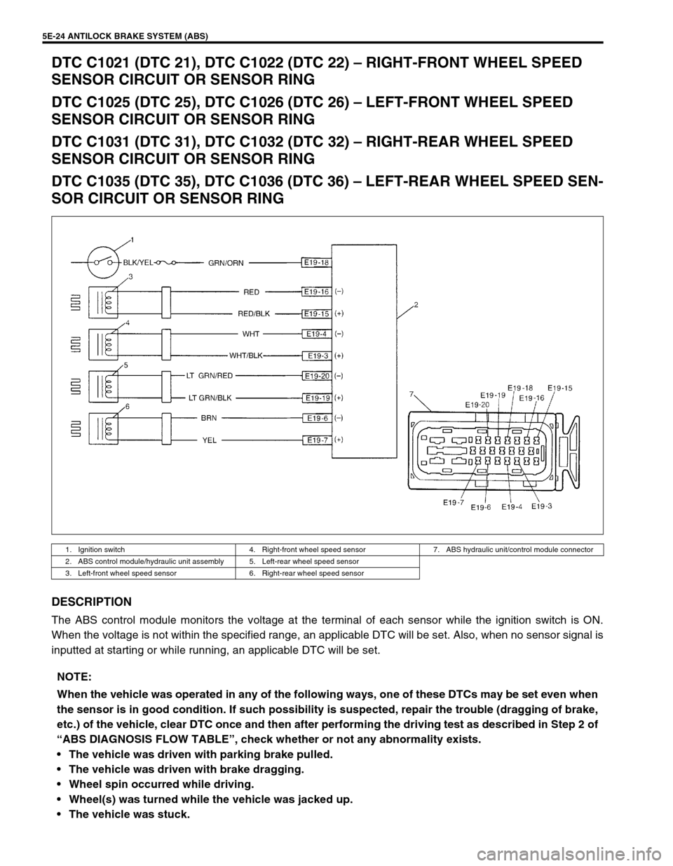
DTC C1021 (DTC 21), DTC C1022 (DTC 22) – RIGHT-FRONT WHEEL SPEED
SENSOR CIRCUIT OR SENSOR RING
DTC C1025 (DTC 25), DTC C1026 (DTC 26) – LEFT-FRONT WHEEL SPEED
SENSOR CIRCUIT OR SENSOR RING
DTC C1031 (DTC 31), DTC C1032 (DTC 32) – RIGHT-REAR WHEEL SPEED
SENSOR CIRCUIT OR SENSOR RING
DTC C1035 (DTC 35), DTC C1036 (DTC 36) – LEFT-REAR WHEEL SPEED SEN-
SOR CIRCUIT OR SENSOR RING
DESCRIPTION
The ABS control module monitors the voltage at the terminal of each sensor while the ignition switch is ON.
When the voltage is not within the specified range, an applicable DTC will be set. Also, when no sensor signal is
inputted at starting or while running, an applicable DTC will be set.
1. Ignition switch 4. Right-front wheel speed sensor 7. ABS hydraulic unit/control module connector
2. ABS control module/hydraulic unit assembly 5. Left-rear wheel speed sensor
3. Left-front wheel speed sensor 6. Right-rear wheel speed sensor
NOTE:
When the vehicle was operated in any of the following ways, one of these DTCs may be set even when
the sensor is in good condition. If such possibility is suspected, repair the trouble (dragging of brake,
etc.) of the vehicle, clear DTC once and then after performing the driving test as described in Step 2 of
“ABS DIAGNOSIS FLOW TABLE”, check whether or not any abnormality exists.
The vehicle was driven with parking brake pulled.
The vehicle was driven with brake dragging.
Wheel spin occurred while driving.
Wheel(s) was turned while the vehicle was jacked up.
The vehicle was stuck.
Page 356 of 698
ANTILOCK BRAKE SYSTEM (ABS) 5E-31
ON-VEHICLE SERVICE
PRECAUTIONS
When connector is connected to ABS hydraulic unit/control mod-
ule assembly, do not disconnect connectors of sensors with igni-
tion switch ON. Then DTC will be set in ABS control module.
ABS HYDRAULIC UNIT OPERATION CHECK
(USING SUZUKI SCAN TOOL)
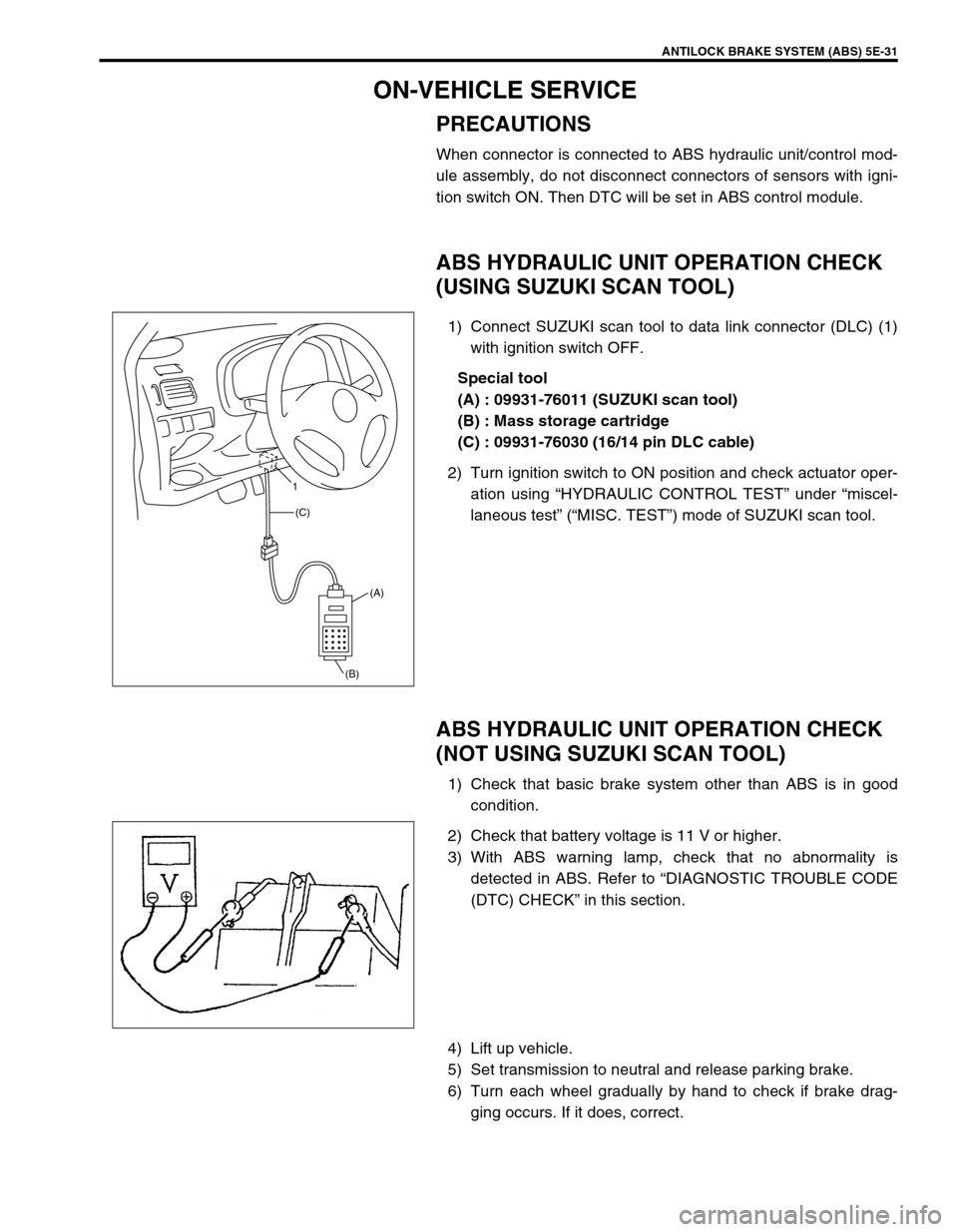
1) Connect SUZUKI scan tool to data link connector (DLC) (1)
with ignition switch OFF.
Special tool
(A) : 09931-76011 (SUZUKI scan tool)
(B) : Mass storage cartridge
(C) : 09931-76030 (16/14 pin DLC cable)
2) Turn ignition switch to ON position and check actuator oper-
ation using “HYDRAULIC CONTROL TEST” under “miscel-
laneous test” (“MISC. TEST”) mode of SUZUKI scan tool.
ABS HYDRAULIC UNIT OPERATION CHECK
(NOT USING SUZUKI SCAN TOOL)
1) Check that basic brake system other than ABS is in good
condition.
2) Check that battery voltage is 11 V or higher.
3) With ABS warning lamp, check that no abnormality is
detected in ABS. Refer to “DIAGNOSTIC TROUBLE CODE
(DTC) CHECK” in this section.
4) Lift up vehicle.
5) Set transmission to neutral and release parking brake.
6) Turn each wheel gradually by hand to check if brake drag-
ging occurs. If it does, correct.
(A)
(B) (C) 1
Page 375 of 698
6-6 ENGINE GENERAL INFORMATION AND DIAGNOSIS
FUEL PRESSURE RELIEF PROCEDURE
After making sure that engine is cold, release fuel pressure as fol-
lows.
1) Place transmission gear shift lever in “Neutral” (Shift selector
lever to “P” range for A/T model), set parking brake, and
block drive wheels.
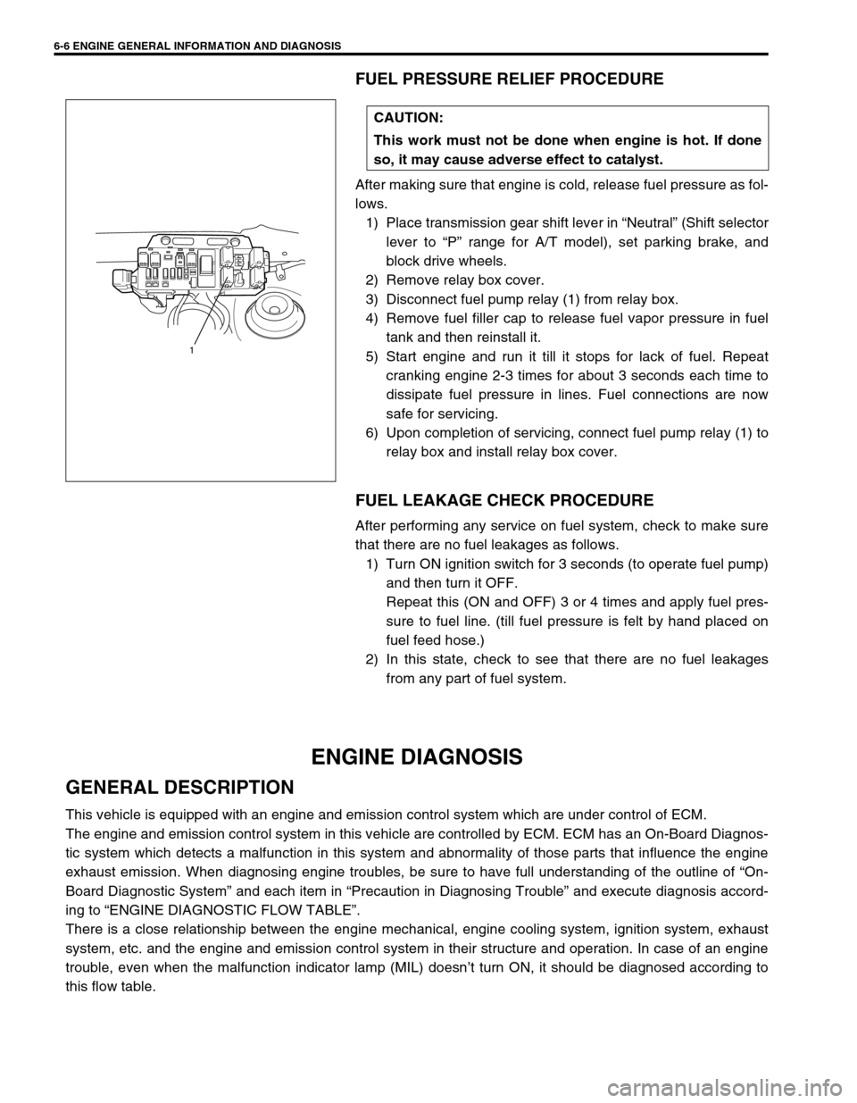
2) Remove relay box cover.
3) Disconnect fuel pump relay (1) from relay box.
4) Remove fuel filler cap to release fuel vapor pressure in fuel
tank and then reinstall it.
5) Start engine and run it till it stops for lack of fuel. Repeat
cranking engine 2-3 times for about 3 seconds each time to
dissipate fuel pressure in lines. Fuel connections are now
safe for servicing.
6) Upon completion of servicing, connect fuel pump relay (1) to
relay box and install relay box cover.
FUEL LEAKAGE CHECK PROCEDURE
After performing any service on fuel system, check to make sure
that there are no fuel leakages as follows.
1) Turn ON ignition switch for 3 seconds (to operate fuel pump)
and then turn it OFF.
Repeat this (ON and OFF) 3 or 4 times and apply fuel pres-
sure to fuel line. (till fuel pressure is felt by hand placed on
fuel feed hose.)
2) In this state, check to see that there are no fuel leakages
from any part of fuel system.
ENGINE DIAGNOSIS
GENERAL DESCRIPTION
This vehicle is equipped with an engine and emission control system which are under control of ECM.
The engine and emission control system in this vehicle are controlled by ECM. ECM has an On-Board Diagnos-
tic system which detects a malfunction in this system and abnormality of those parts that influence the engine
exhaust emission. When diagnosing engine troubles, be sure to have full understanding of the outline of “On-
Board Diagnostic System” and each item in “Precaution in Diagnosing Trouble” and execute diagnosis accord-
ing to “ENGINE DIAGNOSTIC FLOW TABLE”.
There is a close relationship between the engine mechanical, engine cooling system, ignition system, exhaust
system, etc. and the engine and emission control system in their structure and operation. In case of an engine
trouble, even when the malfunction indicator lamp (MIL) doesn’t turn ON, it should be diagnosed according to
this flow table.CAUTION:
This work must not be done when engine is hot. If done
so, it may cause adverse effect to catalyst.
1
Page 400 of 698
ENGINE GENERAL INFORMATION AND DIAGNOSIS 6-31
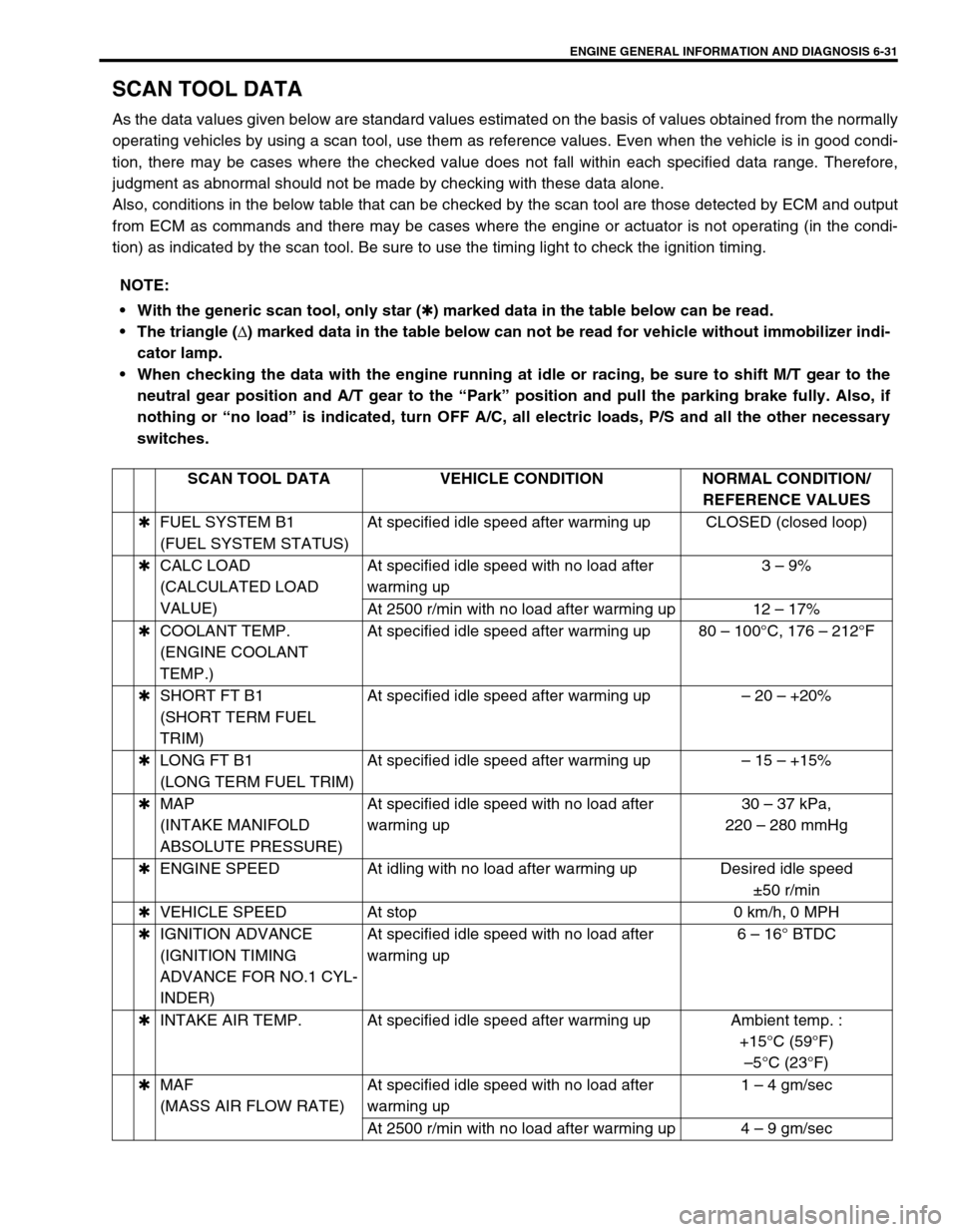
SCAN TOOL DATA
As the data values given below are standard values estimated on the basis of values obtained from the normally
operating vehicles by using a scan tool, use them as reference values. Even when the vehicle is in good condi-
tion, there may be cases where the checked value does not fall within each specified data range. Therefore,
judgment as abnormal should not be made by checking with these data alone.
Also, conditions in the below table that can be checked by the scan tool are those detected by ECM and output
from ECM as commands and there may be cases where the engine or actuator is not operating (in the condi-
tion) as indicated by the scan tool. Be sure to use the timing light to check the ignition timing.
NOTE:
With the generic scan tool, only star (
✱) marked data in the table below can be read.
The triangle (
∆) marked data in the table below can not be read for vehicle without immobilizer indi-
cator lamp.
When checking the data with the engine running at idle or racing, be sure to shift M/T gear to the
neutral gear position and A/T gear to the “Park” position and pull the parking brake fully. Also, if
nothing or “no load” is indicated, turn OFF A/C, all electric loads, P/S and all the other necessary
switches.
SCAN TOOL DATA VEHICLE CONDITION NORMAL CONDITION/
REFERENCE VALUES
✱FUEL SYSTEM B1
(FUEL SYSTEM STATUS)At specified idle speed after warming up CLOSED (closed loop)
✱CALC LOAD
(CALCULATED LOAD
VALUE)At specified idle speed with no load after
warming up3 – 9%
At 2500 r/min with no load after warming up 12 – 17%
✱COOLANT TEMP.
(ENGINE COOLANT
TEMP.)At specified idle speed after warming up 80 – 100°C, 176 – 212°F
✱SHORT FT B1
(SHORT TERM FUEL
TRIM)At specified idle speed after warming up– 20 – +20%
✱LONG FT B1
(LONG TERM FUEL TRIM)At specified idle speed after warming up– 15 – +15%
✱MAP
(INTAKE MANIFOLD
ABSOLUTE PRESSURE)At specified idle speed with no load after
warming up30 – 37 kPa,
220 – 280 mmHg
✱ENGINE SPEED At idling with no load after warming up Desired idle speed
±50 r/min
✱VEHICLE SPEED At stop 0 km/h, 0 MPH
✱IGNITION ADVANCE
(IGNITION TIMING
ADVANCE FOR NO.1 CYL-
INDER)At specified idle speed with no load after
warming up6 – 16° BTDC
✱INTAKE AIR TEMP. At specified idle speed after warming up Ambient temp. :
+15°C (59°F)
–5°C (23°F)
✱MAF
(MASS AIR FLOW RATE)At specified idle speed with no load after
warming up1 – 4 gm/sec
At 2500 r/min with no load after warming up 4 – 9 gm/sec
Page 475 of 698
6-106 ENGINE GENERAL INFORMATION AND DIAGNOSIS
INSPECTION
Fig. 1 for Step 3Step Action Yes No
1Was “ENGINE DIAG. FLOW TABLE” per-
formed?Go to Step 2. Go to “ENGINE DIAG.
FLOW TABLE”.
2 Is SUZUKI scan tool available? Go to Step 3. Go to Step 4.
3 Check Idle Air Control System.
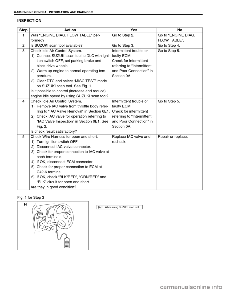
1) Connect SUZUKI scan tool to DLC with igni-
tion switch OFF, set parking brake and
block drive wheels.
2) Warm up engine to normal operating tem-
perature.
3) Clear DTC and select “MISC TEST” mode
on SUZUKI scan tool. See Fig. 1.
Is it possible to control (increase and reduce)
engine idle speed by using SUZUKI scan tool? Intermittent trouble or
faulty ECM.
Check for intermittent
referring to “Intermittent
and Poor Connection” in
Section 0A.Go to Step 5.
4 Check Idle Air Control System.
1) Remove IAC valve from throttle body refer-
ring to “IAC Valve Removal” in Section 6E1.
2) Check IAC valve for operation referring to
“IAC Valve Inspection” in Section 6E1. See
Fig. 2.
Is check result satisfactory?Intermittent trouble or
faulty ECM.
Check for intermittent
referring to “Intermittent
and Poor Connection” in
Section 0A.Go to Step 5.
5 Check Wire Harness for open and short.
1) Turn ignition switch OFF.
2) Disconnect IAC valve connector.
3) Check for proper connection to IAC valve at
each terminals.
4) If OK, disconnect ECM connector.
5) Check for proper connection to ECM at
C42-6 terminal.
6) If OK, check “BLK/RED”, “GRN/RED” and
“BLK” circuit for open and short.
Are they in good condition?Replace IAC valve and
recheck.Repair or replace.
[A] : When using SUZUKI scan tool:[ A]
Page 505 of 698

6A1-4 ENGINE MECHANICAL (M13 ENGINE)
DIAGNOSIS
DIAGNOSIS TABLE
Refer to “ENGINE MECHANICAL DIAGNOSIS TABLE” in Sec-
tion 6.
COMPRESSION CHECK
Check compression pressure on all 4 cylinders as follows:
1) Warm up engine to normal operating temperature.
2) Stop engine after warming up.
3) Remove air cleaner assembly (1), resonator (2) and hoses.
Refer to “AIR CLEANER ASSEMBLY AND RESONATOR”.
4) Remove cylinder head upper cover (1).
5) Disconnect ignition coil couplers (1).
6) Remove ignition coil assemblies (2) with high-tension cord
(3).
7) Remove all spark plugs.
8) Disconnect fuel injector wires (4) at the coupler.NOTE:
After warming up engine, place transmission gear shift
lever in “Neutral” (shift selector lever to “P” range for A/T
model), and set parking brake and block drive wheels.
Page 507 of 698
6A1-6 ENGINE MECHANICAL (M13 ENGINE)
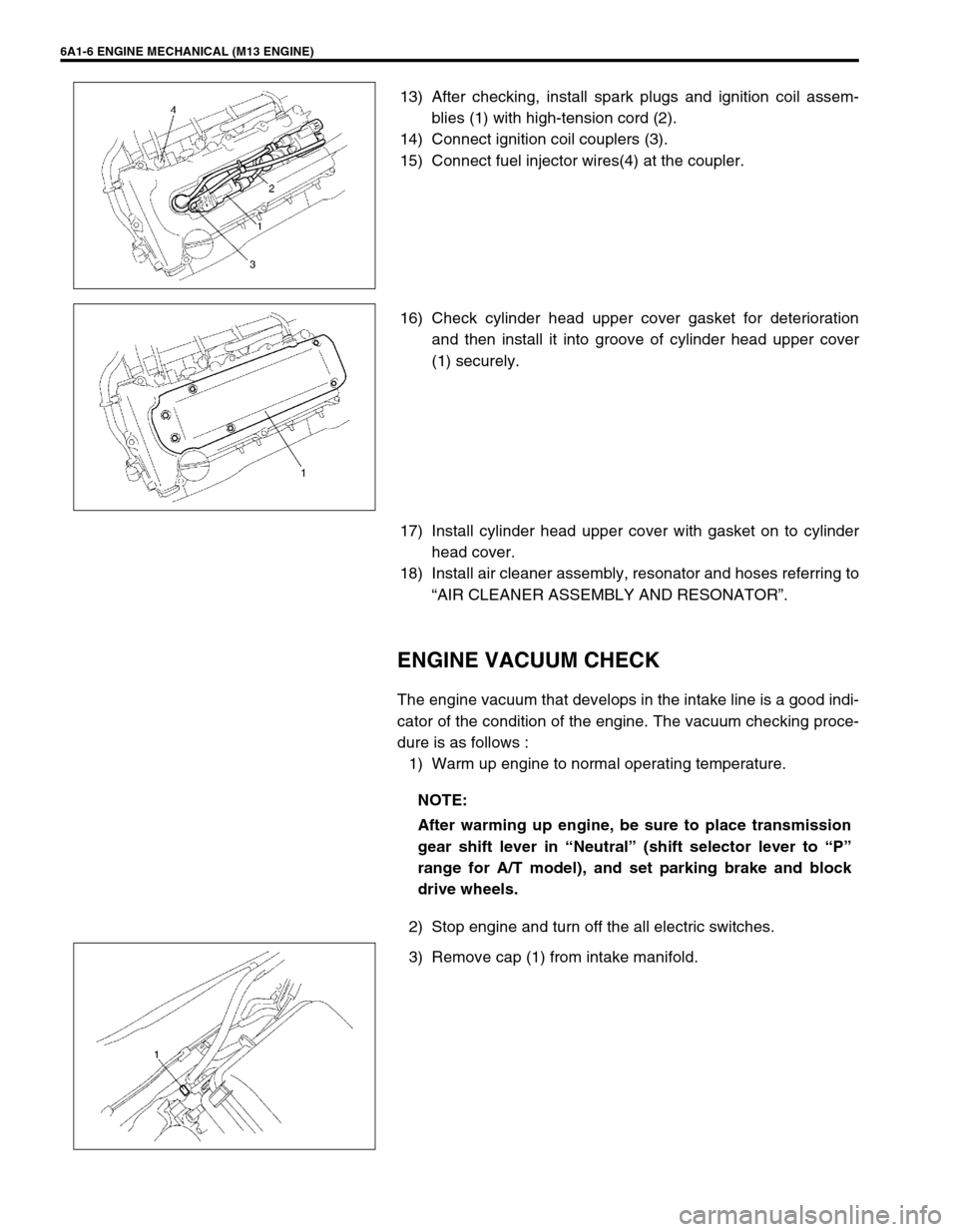
13) After checking, install spark plugs and ignition coil assem-
blies (1) with high-tension cord (2).
14) Connect ignition coil couplers (3).
15) Connect fuel injector wires(4) at the coupler.
16) Check cylinder head upper cover gasket for deterioration
and then install it into groove of cylinder head upper cover
(1) securely.
17) Install cylinder head upper cover with gasket on to cylinder
head cover.
18) Install air cleaner assembly, resonator and hoses referring to
“AIR CLEANER ASSEMBLY AND RESONATOR”.
ENGINE VACUUM CHECK
The engine vacuum that develops in the intake line is a good indi-
cator of the condition of the engine. The vacuum checking proce-
dure is as follows :
1) Warm up engine to normal operating temperature.
2) Stop engine and turn off the all electric switches.
3) Remove cap (1) from intake manifold.
NOTE:
After warming up engine, be sure to place transmission
gear shift lever in “Neutral” (shift selector lever to “P”
range for A/T model), and set parking brake and block
drive wheels.