warning SUZUKI SWIFT 2000 1.G RG413 Service Owner's Manual
[x] Cancel search | Manufacturer: SUZUKI, Model Year: 2000, Model line: SWIFT, Model: SUZUKI SWIFT 2000 1.GPages: 698, PDF Size: 16.01 MB
Page 89 of 698
1B-24 AIR CONDITIONING (OPTIONAL)
CHARGING
CHARGING PROCEDURE
The initial charging of the A/C system is performed from the high
pressure side with the engine stopped.
And next, this method must be followed by charging from the low
pressure side with the engine running.
1) Check to make sure that hoses are routed properly after
evacuating the system.
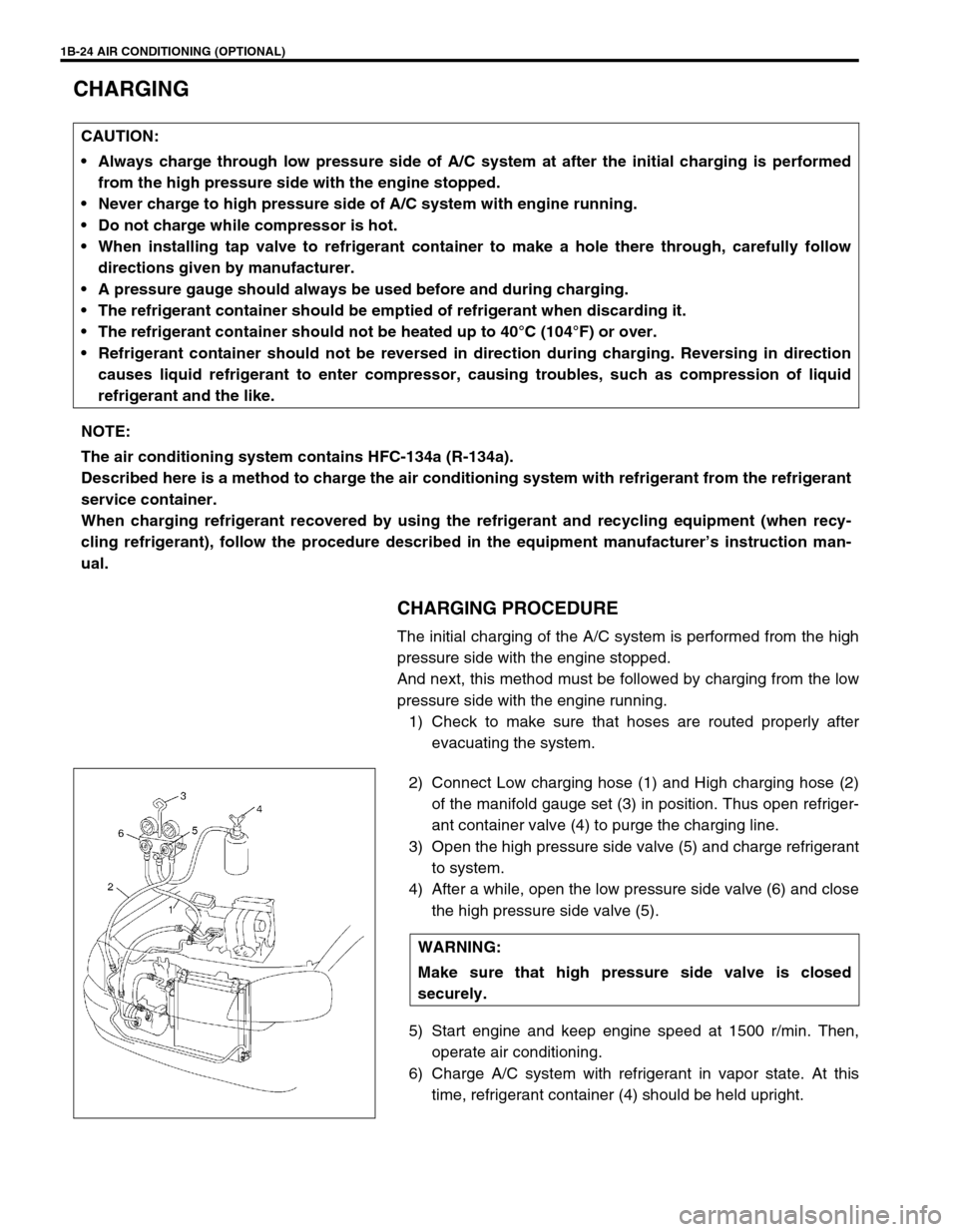
2) Connect Low charging hose (1) and High charging hose (2)
of the manifold gauge set (3) in position. Thus open refriger-
ant container valve (4) to purge the charging line.
3) Open the high pressure side valve (5) and charge refrigerant
to system.
4) After a while, open the low pressure side valve (6) and close
the high pressure side valve (5).
5) Start engine and keep engine speed at 1500 r/min. Then,
operate air conditioning.
6) Charge A/C system with refrigerant in vapor state. At this
time, refrigerant container (4) should be held upright. CAUTION:
Always charge through low pressure side of A/C system at after the initial charging is performed
from the high pressure side with the engine stopped.
Never charge to high pressure side of A/C system with engine running.
Do not charge while compressor is hot.
When installing tap valve to refrigerant container to make a hole there through, carefully follow
directions given by manufacturer.
A pressure gauge should always be used before and during charging.
The refrigerant container should be emptied of refrigerant when discarding it.
The refrigerant container should not be heated up to 40°C (104°F) or over.
Refrigerant container should not be reversed in direction during charging. Reversing in direction
causes liquid refrigerant to enter compressor, causing troubles, such as compression of liquid
refrigerant and the like.
NOTE:
The air conditioning system contains HFC-134a (R-134a).
Described here is a method to charge the air conditioning system with refrigerant from the refrigerant
service container.
When charging refrigerant recovered by using the refrigerant and recycling equipment (when recy-
cling refrigerant), follow the procedure described in the equipment manufacturer’s instruction man-
ual.
WARNING:
Make sure that high pressure side valve is closed
securely.
Page 91 of 698
1B-26 AIR CONDITIONING (OPTIONAL)
REMOVING MANIFOLD GAUGE SET
When A/C system has been charged with a specified amount of refrigerant, remove manifold gauge set as fol-
lows :
1) Close low pressure side valve of manifold gauge set. (The high pressure side valve is closed continuously
during the process of charging.)
2) Close refrigerant container valve.
3) Stop engine.
4) Using shop rag, remove charging hoses from service valves. This operation must be performed rapidly.
5) Put caps on service valves.
LEAK TEST
Whenever a refrigerant leak is suspected in the system or any
service operation has been performed which may result in dis-
turbing lines or connections, it is advisable to test for leaks.
Common sense should be used in performing any refrigerant leak
test, since the need and extent of any such test will, in general,
depend upon the nature of a complaint and the type of a service
performed on the system.
LIQUID LEAK DETECTORS
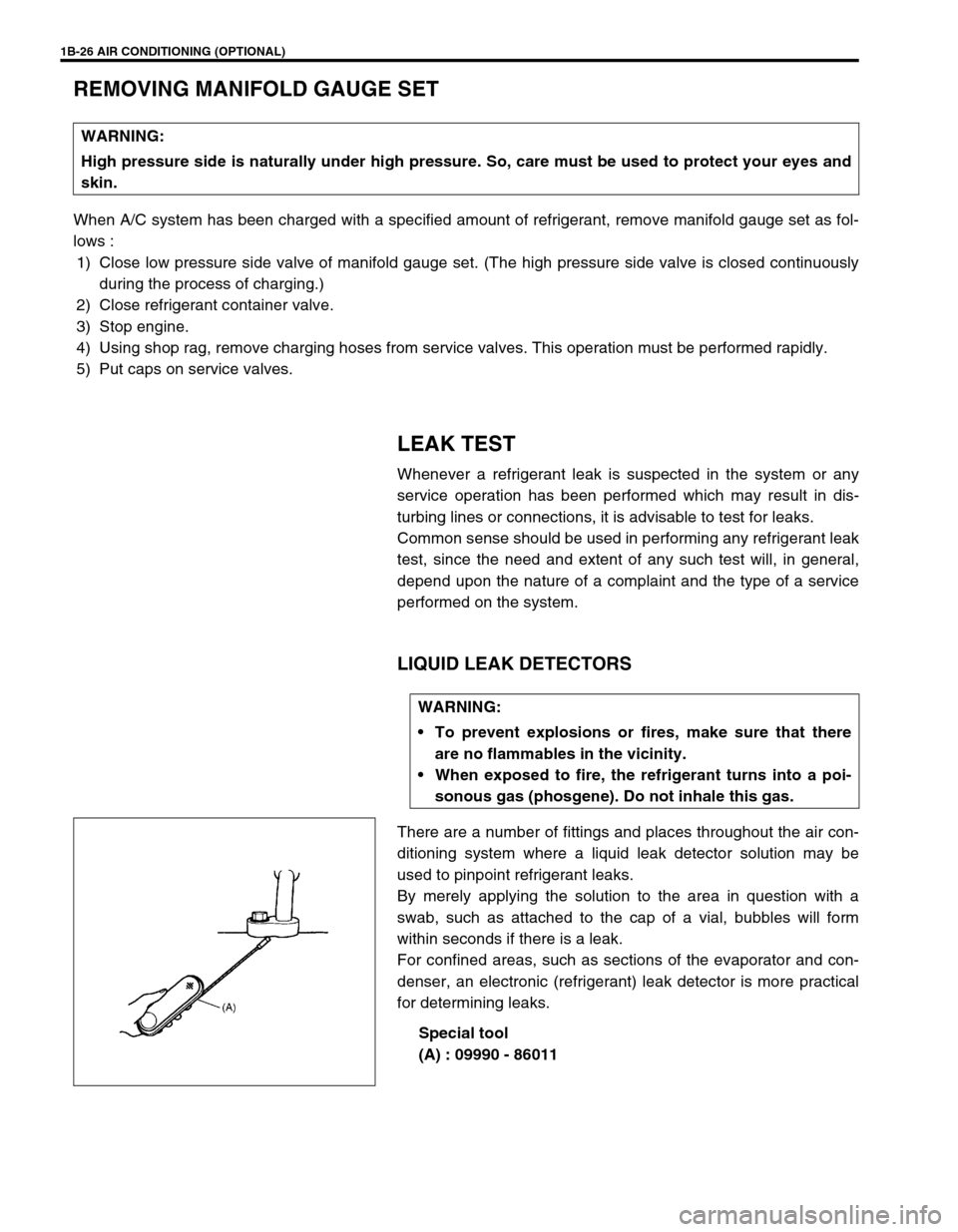
There are a number of fittings and places throughout the air con-
ditioning system where a liquid leak detector solution may be
used to pinpoint refrigerant leaks.
By merely applying the solution to the area in question with a
swab, such as attached to the cap of a vial, bubbles will form
within seconds if there is a leak.
For confined areas, such as sections of the evaporator and con-
denser, an electronic (refrigerant) leak detector is more practical
for determining leaks.
Special tool
(A) : 09990 - 86011 WARNING:
High pressure side is naturally under high pressure. So, care must be used to protect your eyes and
skin.
WARNING:
To prevent explosions or fires, make sure that there
are no flammables in the vicinity.
When exposed to fire, the refrigerant turns into a poi-
sonous gas (phosgene). Do not inhale this gas.
Page 92 of 698
AIR CONDITIONING (OPTIONAL) 1B-27
ON-VEHICLE SERVICE
SERVICE PRECAUTION
When servicing air conditioning system, note the following instructions.
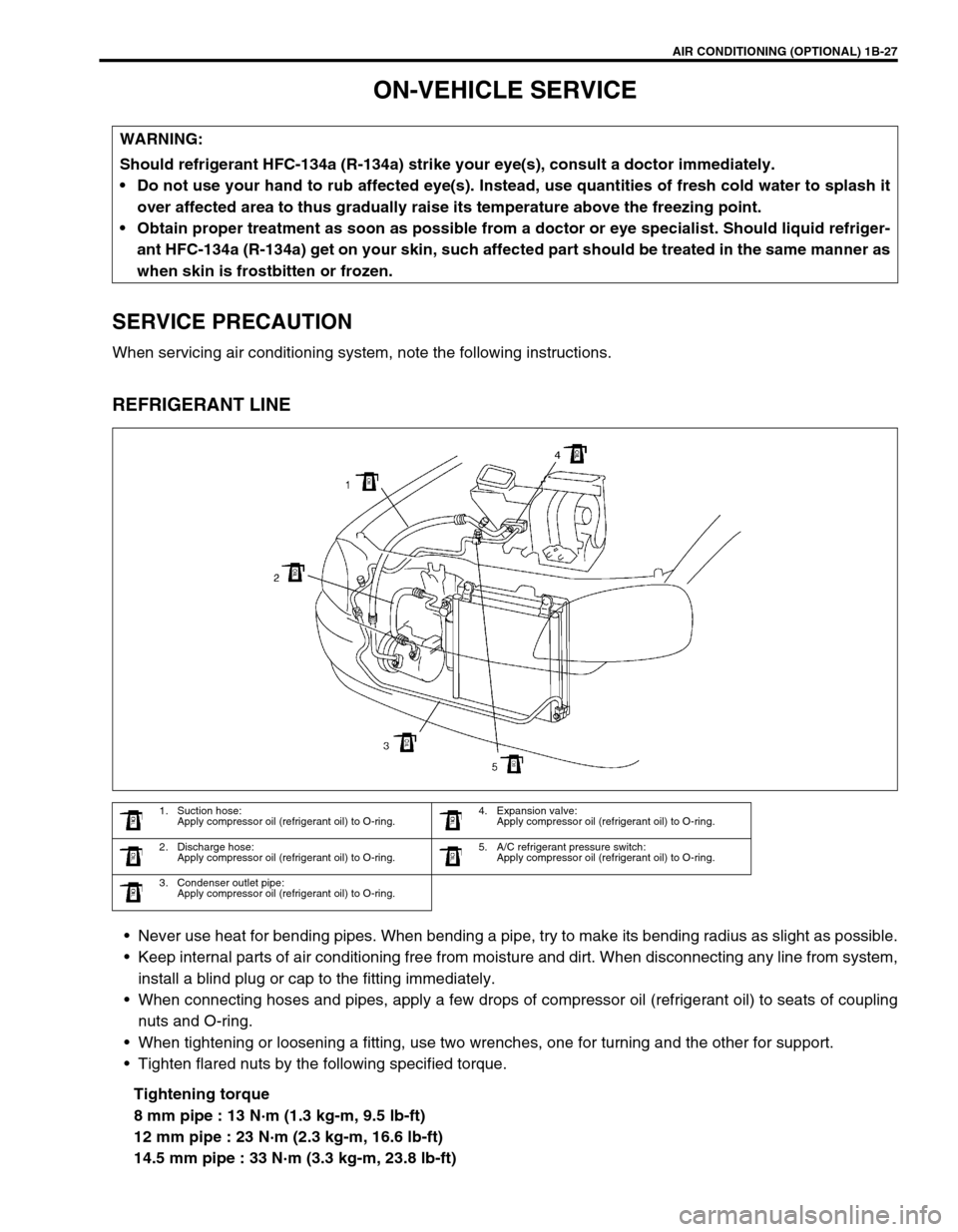
REFRIGERANT LINE
Never use heat for bending pipes. When bending a pipe, try to make its bending radius as slight as possible.
Keep internal parts of air conditioning free from moisture and dirt. When disconnecting any line from system,
install a blind plug or cap to the fitting immediately.
When connecting hoses and pipes, apply a few drops of compressor oil (refrigerant oil) to seats of coupling
nuts and O-ring.
When tightening or loosening a fitting, use two wrenches, one for turning and the other for support.
Tighten flared nuts by the following specified torque.
Tightening torque
8 mm pipe : 13 N·m (1.3 kg-m, 9.5 lb-ft)
12 mm pipe : 23 N·m (2.3 kg-m, 16.6 lb-ft)
14.5 mm pipe : 33 N·m (3.3 kg-m, 23.8 lb-ft) WARNING:
Should refrigerant HFC-134a (R-134a) strike your eye(s), consult a doctor immediately.
Do not use your hand to rub affected eye(s). Instead, use quantities of fresh cold water to splash it
over affected area to thus gradually raise its temperature above the freezing point.
Obtain proper treatment as soon as possible from a doctor or eye specialist. Should liquid refriger-
ant HFC-134a (R-134a) get on your skin, such affected part should be treated in the same manner as
when skin is frostbitten or frozen.
1. Suction hose:
Apply compressor oil (refrigerant oil) to O-ring.4. Expansion valve:
Apply compressor oil (refrigerant oil) to O-ring.
2. Discharge hose:
Apply compressor oil (refrigerant oil) to O-ring.5. A/C refrigerant pressure switch:
Apply compressor oil (refrigerant oil) to O-ring.
3. Condenser outlet pipe:
Apply compressor oil (refrigerant oil) to O-ring.
Page 122 of 698
MANUAL RACK AND PINION 3B-1
6F1
6F2
6G
6H
7A
3B
7C1
7D
7E
7F
8A
8B
8C
8D
8E
9
10
10A
10B
SECTION 3B
MANUAL RACK AND PINION
CONTENTS
GENERAL DESCRIPTION .............................. 3B-2
DIAGNOSIS ..................................................... 3B-3
ON-VEHICLE SERVICE .................................. 3B-4
LUBRICATION ............................................. 3B-4
TIE ROD END .............................................. 3B-6
MANUAL RACK AND PINION ASSEMBLY
(STEERING GEAR CASE) .......................... 3B-7
RACK BOOT/TIE ROD .............................. 3B-10STEERING RACK PLUNGER ................... 3B-12
STEERING PINION ................................... 3B-14
STEERING RACK...................................... 3B-15
PINION BEARING ..................................... 3B-17
RACK BUSHING ........................................ 3B-18
REQUIRED SERVICE MATERIAL................ 3B-19
SPECIAL TOOL ............................................ 3B-20
WARNING:
For vehicles equipped with a Air Bag System
Service on or around air bag system components or wiring must be performed only by an autho-
rized suzuki dealer. Please observe all WARNINGS and CAUTIONS in SECTION 10B and Precau-
tions, Air Bag System Components and Wiring Location view in Section 10B before performing
service on or around air bag system components or wiring. Failure to follow WARNINGS could
result in unintended activation of the system or could render the system inoperative. Either of these
two conditions may result in severe injury.
Technical service work must be started at least 90 seconds after the ignition switch is turned to the
“LOCK” position and the negative cable is disconnected from the battery. Otherwise, the system
may be deployed by reserve energy in the Sensing and Diagnostic Module (SDM).
NOTE:
All steering gear fasteners are important attaching parts in that they could affect the performance of
vital parts and systems, and/or could result in major repair expense. They must be replaced with one
of the same part number or with an equivalent part if replacement becomes necessary. Do not use a
replacement part of lesser quality or substitute design. Torque values must be used as specified dur-
ing reassembly to assure proper retention of these parts.
Page 142 of 698
ELECTRICAL POWER STEERING (P/S) SYSTEM 3B1-1
6F1
6F2
6G
6H
6K
7A
7A1
3B1
7D
7E
7F
8A
8B
8C
8D
8E
9
10
10A
10B
SECTION 3B1
ELECTRICAL POWER STEERING (P/S) SYSTEM
CONTENTS
GENERAL DESCRIPTION .............................3B1-2
SYSTEM COMPONENTS ........................... 3B1-2
WIRING DIAGRAM ..................................... 3B1-3
DIAGNOSIS ....................................................3B1-4
ON-BOARD DIAGNOSTIC SYSTEM .......... 3B1-4
PRECAUTIONS IN DIAGNOSING
TROUBLES ................................................. 3B1-4
SYSTEM CHECK FLOW TABLE ................ 3B1-5
MALFUNCTION INDICATOR LAMP
(“EPS” WARNING LAMP) CHECK.............. 3B1-7
DTC CHECK ............................................... 3B1-8
DTC CLEARANCE ...................................... 3B1-9
SERIAL DATA LINK CIRCUIT CHECK ..... 3B1-10
DTC TABLE .............................................. 3B1-11
TABLE A - MALFUNCTION INDICATOR
LAMP DOES NOT COME ON AT
IGNITION SWITCH ON BUT LEAVING
ENGINE OFF ............................................ 3B1-13
TABLE B - MALFUNCTION INDICATOR
LAMP FLASHES AT IGNITION SWITCH
ON ............................................................. 3B1-15
TABLE C - MALFUNCTION INDICATOR
LAMP DOES NOT FLASH, JUST
REMAINS ON OR JUST REMAINS OFF
EVEN WITH DIAGNOSIS SWITCH
TERMINAL GROUNDED .......................... 3B1-15
DTC C1111 (DTC No.11) TORQUE
SENSOR MAIN CIRCUIT FAILURE ......... 3B1-16
DTC C1113 (DTC No.13) TORQUE
SENSOR MAIN AND SUB CIRCUIT
FAILURE ................................................... 3B1-16DTC C1115 (DTC No.15) TORQUE
SENSOR SUB CIRCUIT FAILURE........... 3B1-16
DTC C1114 (DTC No.14) TORQUE
SENSOR 5V POWER SUPPLY CIRCUIT
FAILURE ................................................... 3B1-17
DTC C1116 (DTC No.16) TORQUE
SENSOR 8V POWER SUPPLY CIRCUIT
FAILURE ................................................... 3B1-18
DTC C1121/C1123/C1124
(DTC No.21/23/24) VSS CIRCUIT
FAILURE ................................................... 3B1-19
DTC C1122 (DTC No.22) ENGINE
SPEED SIGNAL CIRCUIT FAILURE ........ 3B1-20
DTC C1141/C1142/C1143/C1144/C1145
(DTC No.41/42/43/44/45) MOTOR
CIRCUIT FAILURE ................................... 3B1-21
DTC C1151 (DTC No.51) CLUTCH
CIRCUIT FAILURE ................................... 3B1-22
DTC C1153(DTC No.53) P/S CONTROL
MODULE POWER SUPPLY CIRCUIT
FAILURE ................................................... 3B1-24
DTC C1152/C1154/C1155
(DTC No.52/54/55) P/S CONTROL
MODULE FAILURE .................................. 3B1-24
TROUBLE DIAGNOSIS (FOR TROUBLE
NOT INDICATED BY ON BOARD
DIAGNOSTIC SYSTEM)........................... 3B1-25
INSPECTION OF P/S CONTROL
MODULE AND ITS CIRCUITS ................. 3B1-26
STEERING WHEEL PLAY
INSPECTION ............................................ 3B1-28 WARNING:
For vehicles equipped with Supplemental Restraint (Air Bag) System :
Service on and around the air bag system components or wiring must be performed only by an
authorized SUZUKI dealer. Refer to “Air Bag System Components and Wiring Location View” under
“General Description” in air bag system section in order to confirm whether you are performing ser-
vice on or near the air bag system components or wiring. Please observe all WARNINGS and “Ser-
vice Precautions” under “On-Vehicle Service” in air bag system section before performing service
on or around the air bag system components or wiring. Failure to follow WARNINGS could result in
unintentional activation of the system or could render the system inoperative. Either of these two
conditions may result in severe injury.
Technical service work must be started at least 90 seconds after the ignition switch is turned to the
“LOCK” position and the negative cable is disconnected from the battery. Otherwise, the system
may be activated by reserve energy in the Sensing and Diagnostic Module (SDM).
Page 144 of 698
ELECTRICAL POWER STEERING (P/S) SYSTEM 3B1-3
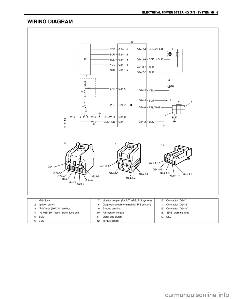
WIRING DIAGRAM
BLK RED
BLK
BLK
BLU
BLK YEL BLU
BLK
YEL
WHT
BRN
PPLBLK/WHT
BLK/RED
PPL/WHTBLK or RED
RED or BLK G24-1-1 G24-2-2
G24-2-1
G24-2-4
G24-2-3
G24-5
G24-3
G24-4
G24-2 G24-1-2
G24-1-3
G24-1-4
G24-1-5
G24-6
G24-8
G24-1 G24-7 12
5
6
124
378
9171611 10
G24-1
G24-3
G24-4
G24-5
G24-6
G24-7G24-8G24-2
13
G24-2-2
G24-2-4 G24-2-3 G24-2-1
14
G24-1-5
G24-1-4 G24-1-3 G24-1-2 G24-1-115
1. Main fuse 7. Monitor coupler (for A/T, ABS, P/S system) 13. Connector “G24”
2. Ignition switch 8. Diagnosis switch terminal (for P/S system) 14. Connector “G24-2”
3.“P/S” fuse (30A) in fuse box 9. Ground terminal 15. Connector “G24-1”
4.“IG METER” fuse (15A) in fuse box 10. P/S control module 16.“EPS” warning lamp
5. ECM 11. Motor and clutch 17. DLC
6. VSS 12. Torque sensor
Page 145 of 698
3B1-4 ELECTRICAL POWER STEERING (P/S) SYSTEM
DIAGNOSIS
The P/S system in this vehicle is controlled by P/S control module. P/S control module has an on-board diagnos-
tic system which detects a malfunction in this system.
When diagnosing troubles, be sure to have full understanding of the outline of “ON-BOARD DIAGNOSTIC SYS-
TEM” and each item in “PRECAUTION IN DIAGNOSING TROUBLE” and execute diagnosis according to “SYS-
TEM CHECK FLOW TABLE”.
ON-BOARD DIAGNOSTIC SYSTEM
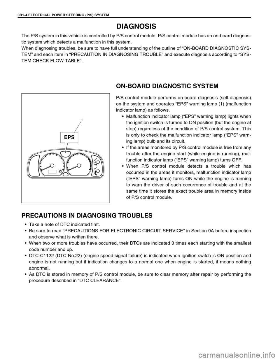
P/S control module performs on-board diagnosis (self-diagnosis)
on the system and operates “EPS” warning lamp (1) (malfunction
indicator lamp) as follows.
Malfunction indicator lamp (“EPS” warning lamp) lights when
the ignition switch is turned to ON position (but the engine at
stop) regardless of the condition of P/S control system. This
is only to check the malfunction indicator lamp (“EPS” warn-
ing lamp) bulb and its circuit.
If the areas monitored by P/S control module is free from any
trouble after the engine start (while engine is running), mal-
function indicator lamp (“EPS” warning lamp) turns OFF.
When P/S control module detects a trouble which has
occurred in the areas it monitors, malfunction indicator lamp
(“EPS” warning lamp) turns ON while the engine is running
to warn the driver of such occurrence of trouble and at the
same time it stores the exact trouble area in memory inside
of P/S control module.
PRECAUTIONS IN DIAGNOSING TROUBLES
Take a note of DTC indicated first.
Be sure to read “PRECAUTIONS FOR ELECTRONIC CIRCUIT SERVICE” in Section 0A before inspection
and observe what is written there.
When two or more troubles have occurred, their DTCs are indicated 3 times each starting with the smallest
code number and up.
DTC C1122 (DTC No.22) (engine speed signal failure) is indicated when ignition switch is ON position and
engine is not running but if indication changes to a normal one when engine is started, it means nothing
abnormal.
As DTC is stored in memory of P/S control module, be sure to clear memory after repair by performing the
procedure described in “DTC CLEARANCE”.
1
Page 146 of 698
ELECTRICAL POWER STEERING (P/S) SYSTEM 3B1-5
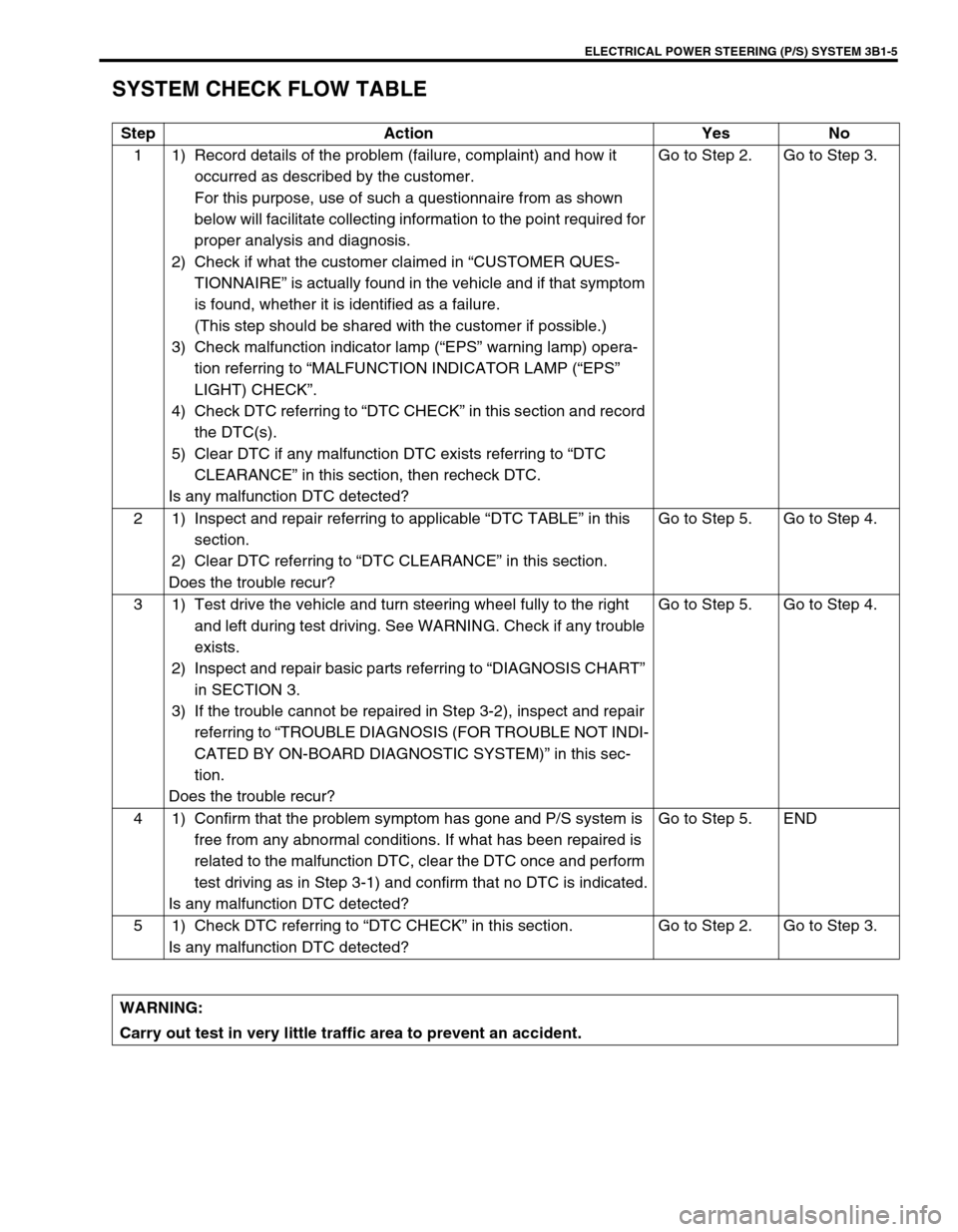
SYSTEM CHECK FLOW TABLE
Step Action Yes No
1 1) Record details of the problem (failure, complaint) and how it
occurred as described by the customer.
For this purpose, use of such a questionnaire from as shown
below will facilitate collecting information to the point required for
proper analysis and diagnosis.
2) Check if what the customer claimed in “CUSTOMER QUES-
TIONNAIRE” is actually found in the vehicle and if that symptom
is found, whether it is identified as a failure.
(This step should be shared with the customer if possible.)
3) Check malfunction indicator lamp (“EPS” warning lamp) opera-
tion referring to “MALFUNCTION INDICATOR LAMP (“EPS”
LIGHT) CHECK”.
4) Check DTC referring to “DTC CHECK” in this section and record
the DTC(s).
5) Clear DTC if any malfunction DTC exists referring to “DTC
CLEARANCE” in this section, then recheck DTC.
Is any malfunction DTC detected?Go to Step 2. Go to Step 3.
2 1) Inspect and repair referring to applicable “DTC TABLE” in this
section.
2) Clear DTC referring to “DTC CLEARANCE” in this section.
Does the trouble recur?Go to Step 5. Go to Step 4.
3 1) Test drive the vehicle and turn steering wheel fully to the right
and left during test driving. See WARNING. Check if any trouble
exists.
2) Inspect and repair basic parts referring to “DIAGNOSIS CHART”
in SECTION 3.
3) If the trouble cannot be repaired in Step 3-2), inspect and repair
referring to “TROUBLE DIAGNOSIS (FOR TROUBLE NOT INDI-
CATED BY ON-BOARD DIAGNOSTIC SYSTEM)” in this sec-
tion.
Does the trouble recur?Go to Step 5. Go to Step 4.
4 1) Confirm that the problem symptom has gone and P/S system is
free from any abnormal conditions. If what has been repaired is
related to the malfunction DTC, clear the DTC once and perform
test driving as in Step 3-1) and confirm that no DTC is indicated.
Is any malfunction DTC detected?Go to Step 5. END
5 1) Check DTC referring to “DTC CHECK” in this section.
Is any malfunction DTC detected?Go to Step 2. Go to Step 3.
WARNING:
Carry out test in very little traffic area to prevent an accident.
Page 147 of 698
3B1-6 ELECTRICAL POWER STEERING (P/S) SYSTEM
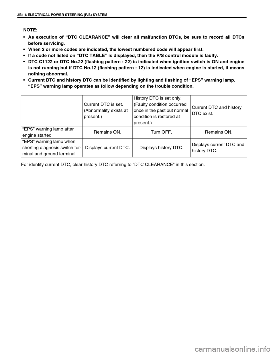
For identify current DTC, clear history DTC referring to “DTC CLEARANCE” in this section. NOTE:
As execution of “DTC CLEARANCE” will clear all malfunction DTCs, be sure to record all DTCs
before servicing.
When 2 or more codes are indicated, the lowest numbered code will appear first.
If a code not listed on “DTC TABLE” is displayed, then the P/S control module is faulty.
DTC C1122 or DTC No.22 (flashing pattern : 22) is indicated when ignition switch is ON and engine
is not running but if DTC No.12 (flashing pattern : 12) is indicated when engine is started, it means
nothing abnormal.
Current DTC and history DTC can be identified by lighting and flashing of “EPS” warning lamp.
“EPS” warning lamp operates as follow depending on the trouble condition.
Current DTC is set.
(Abnormality exists at
present.)History DTC is set only.
(Faulty condition occurred
once in the past but normal
condition is restored at
present.)Current DTC and history
DTC exist.
“EPS” warning lamp after
engine startedRemains ON. Turn OFF. Remains ON.
“EPS” warning lamp when
shorting diagnosis switch ter-
minal and ground terminalDisplays current DTC. Displays history DTC.Displays current DTC and
history DTC.
Page 148 of 698
ELECTRICAL POWER STEERING (P/S) SYSTEM 3B1-7
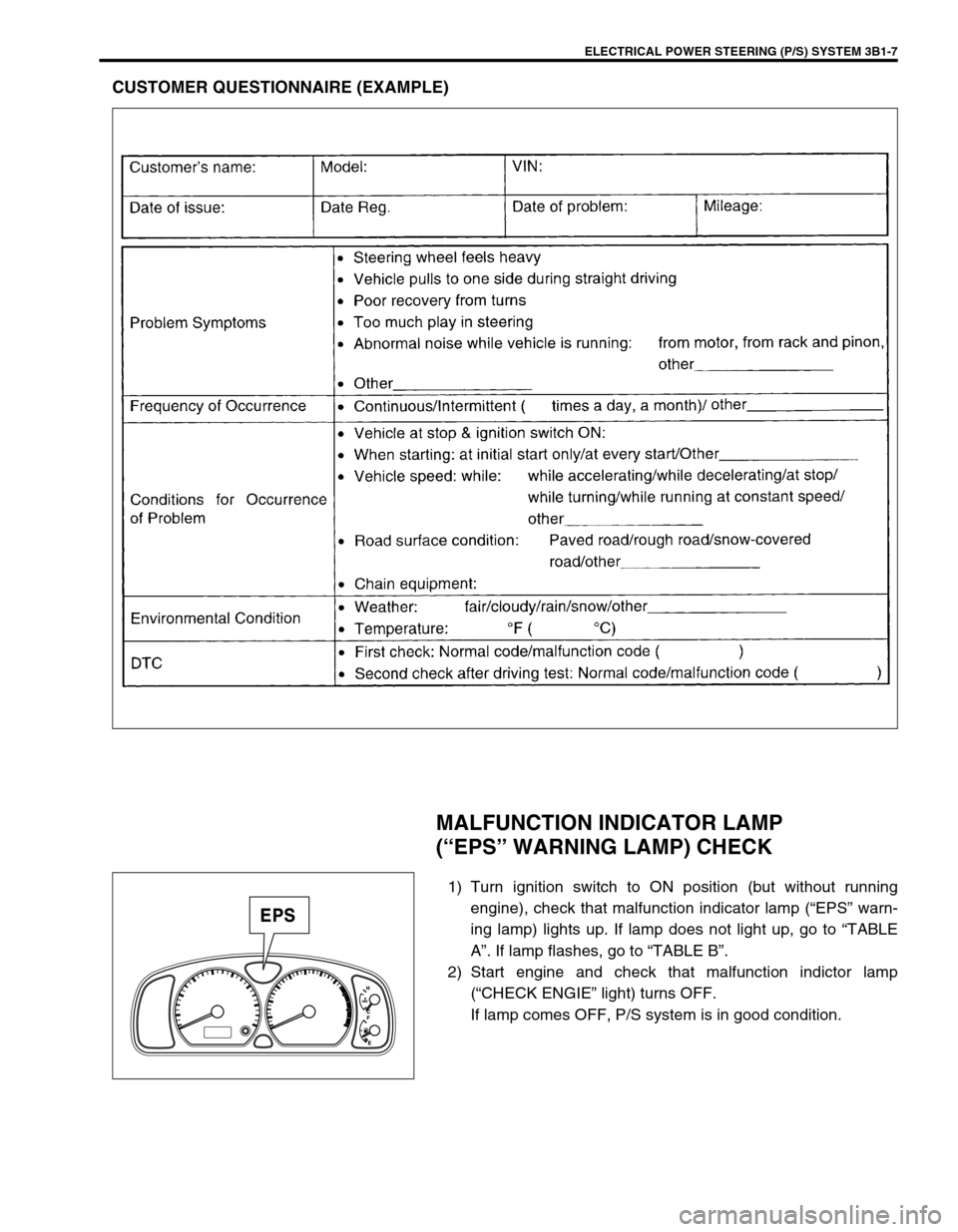
CUSTOMER QUESTIONNAIRE (EXAMPLE)
MALFUNCTION INDICATOR LAMP
(“EPS” WARNING LAMP) CHECK
1) Turn ignition switch to ON position (but without running
engine), check that malfunction indicator lamp (“EPS” warn-
ing lamp) lights up. If lamp does not light up, go to “TABLE
A”. If lamp flashes, go to “TABLE B”.
2) Start engine and check that malfunction indictor lamp
(“CHECK ENGIE” light) turns OFF.
If lamp comes OFF, P/S system is in good condition.